Introduction
Photonic devices in which the flow of light is nonreciprocal, such as optical isolators and circulators, are highly desirable for applications ranging from communications to sensing and metrology. For many years, nonreciprocal photonic devices have been predominantly based on magneto-optical materials, which break Lorentz reciprocity when subjected to a magnetic field. However, magneto-optical devices have several disadvantages—they tend to be bulky, are subject to high losses, and are difficult to integrate into current semiconductor fabrication techniques. An alternative approach to breaking Lorentz reciprocity is to exploit optical nonlinearities, such as the thermo-optic effect, Kerr effect, and two-photon absorption.Reference Soljačić, Luo, Joannopoulos and Fan1–Reference Fan, Varghese, Wang, Xuan, Weiner and Qi3 For instance, Fan et al. have demonstrated an all-silicon optical isolator with a nonreciprocal transmission ratio of more than 28 dB, based on coupled microrings with thermo-optic nonlinearity.Reference Fan, Wang, Varghese, Shen, Niu, Xuan, Weiner and Qi2
This article discusses two recent directions in designing structured nonlinear optical media for nonreciprocal wave transport. The first explores non-Hermitian effects found in open systems with dissipation or amplification, and involves judiciously tailoring the distribution of optical loss or gain.Reference Suchkov, Sukhorukov, Huang, Dmitriev, Lee and Kivshar4–Reference El-Ganainy, Makris, Khajavikhan, Musslimani, Rotter and Christodoulides7 This includes “parity-time-reversal (PT) symmetric” structures that contain balanced amounts of gain and loss, as well as structures exhibiting non-Hermitian degeneracies known as exceptional points (EPs). The second direction consists of photonic structures with “topologically nontrivial” photonic bands.Reference Lu, Joannopoulos and Soljačić8–Reference Ozawa, Price, Amo, Goldman, Hafezi, Lu, Rechtsman, Schuster, Simon, Zilberberg and Carusotto11 Such structures support an unusual class of electromagnetic modes known as topological edge states, analogous to electronic topological edge states in topological insulators, which are robust to defects or perturbations.
In the absence of optical nonlinearity (and the absence of magneto-optical effects and time modulation), synthetic photonic materials cannot break Lorentz reciprocity, even if loss or gain are present.Reference Jalas, Petrov, Eich, Freude, Fan, Yu, Baets, Popović, Melloni, Joannopoulos, Vanwolleghem, Doerr and Renner12 Both effects we focus on—non-Hermiticity and band topology—do not lead to nonreciprocity by themselves. When combined with optical nonlinearity, however, they can be used to achieve highly nonreciprocal behaviors.
Nonlinear and non-Hermitian photonics
The time evolution of a physical system, such as the classical electromagnetic field in a photonic device, can be described by a Hamiltonian that is Hermitian (i.e., H = H †, where † denotes the conjugate transpose operation). Hermiticity guarantees a real energy spectrum and unitary (probability-conserving) time evolution. In practice, however, physical systems often experience loss or gain—in other words, energy enters or leaves the system via processes such as radiative or nonradiative dissipation (loss), or stimulated emission of radiation (gain). Such systems are described by Hamiltonians that are non-Hermitian (i.e., H ≠ H †). They typically exhibit complex spectra, with the imaginary part of each energy eigenvalue representing a dissipation or amplification rate.Reference Bender13
In the past few years, researchers have increasingly come to appreciate the fact that the effects of non-Hermiticity are not necessarily small corrections to Hermitian behavior. Non-Hermitian systems can exhibit features intrinsically different from their Hermitian counterparts. Even a simple two-level system, for instance, can be steered to a non-Hermitian degeneracy known as an EP by tailoring the gain/loss and interlevel couplings. Unlike degeneracies found in conservative systems (i.e., those described by Hermitian Hamiltonians), where only the eigenvalues are degenerate but eigenstates remain orthogonal, an EP is marked by the coalescence of both the eigenvalues and their associated eigenstates. In other words, at an EP, the dimensionality of the eigenspace decreases to one.Reference Kato14
Photonics has proven to be an excellent platform for studying (and ultimately exploiting) non-Hermitian physics, due to the ease with which non-Hermiticity can be controlled, via optical gain/loss and modal coupling.Reference Suchkov, Sukhorukov, Huang, Dmitriev, Lee and Kivshar4–Reference El-Ganainy, Makris, Khajavikhan, Musslimani, Rotter and Christodoulides7 Non-Hermitian effects have been used to modify the flow of light,Reference Feng, Xu, Fegadolli, Lu, Oliveira, Almeida, Chen and Scherer15–Reference Chang, Jiang, Hua, Yang, Wen, Jiang, Li, Wang and Xiao18 stabilize the operation of microlasers,Reference Hodaei, Miri, Heinrich, Christodoulides and Khajavikhan19–Reference Peng, Ozdemir, Liertzer, Chen, Kramer, Yilmaz, Wiersig, Rotter and Yang24 perform optical sensing and metrology,Reference Wiersig25–Reference Hodaei, Hassan, Wittek, Garcia-Gracia, El-Ganainy, Christodoulides and Khajavikhan29 and control optomechanical interactions.Reference Jing, Ozdemir, Lü, Zhang, Yang and Nori30,Reference Xu, Mason, Jiang and Harris31 Furthermore, by combining non-Hermitian effects with optical nonlinearities, it is possible to design devices with strongly nonreciprocal behavior.
Nonreciprocity and PT symmetry
Although non-Hermitian Hamiltonians typically have complex eigenvalues, a special class of them can exhibit real spectra. These are PT symmetric Hamiltonians,Reference Bender and Boettcher32,Reference Bender33 which are invariant under the simultaneous application of a parity and time-reversal operation. Although PT symmetric Hamiltonians were first proposed as a means of generalizing the fundamental laws of quantum mechanics, the greatest progress in realizing such Hamiltonians has been in photonics, using classical electromagnetic fields. In the photonics context, the time-reversal (T) symmetry exchanges optical amplification (gain) and dissipation (loss), so PT symmetry involves placing equal and opposite amounts of gain and loss in two parts of a photonic structure.Reference El-Ganainy, Makris, Christodoulides and Musslimani34 In terms of the complex refractive index n, this means setting n(x) = n(−x)∗, where x denotes the spatial coordinate that is flipped by the parity operation.
A typical PT symmetric photonic structure consists of two coupled components (e.g., optical waveguides or optical resonators), with balanced gain and loss.Reference Peng, Ozdemir, Lei, Monifi, Gianfreda, Long, Fan, Nori, Bender and Yang17,Reference Chang, Jiang, Hua, Yang, Wen, Jiang, Li, Wang and Xiao18,Reference Guo, Salamo, Duchesne, Morandotti, Volatier-Ravat, Aimez, Siviloglou and Christodoulides35,Reference Rüter, Makris, El-Ganainy, Christodoulides, Segev and Kip36 When the coupling is strong, energy in the active component can flow rapidly into the lossy one to compensate its loss. Hence, each optical mode experiences no net gain or loss, and the corresponding eigenfrequency is real; it also maps onto itself under the PT operation, so that the intensities in the two components are equal. The system is then said to be in a “PT unbroken phase.” As the coupling strength is decreased below a critical value, however, the energy exchange is not fast enough to allow such gain/loss balanced modes to exist. The system abruptly undergoes a “PT breaking phase transition,” entering a “PT broken phase.” In the PT broken phase, one optical mode is concentrated in the amplifying component (experiencing gain), and another is concentrated in the lossy component (experiencing loss), with the two modes mapping to each under the PT operation. The transition point is an EP of the Hamiltonian.
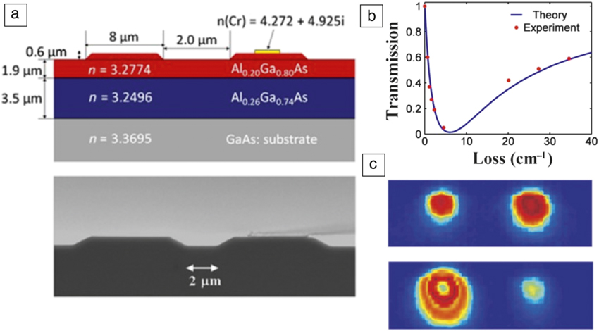
Experimental evidence for a PT breaking transition was first revealed in a system of two coupled optical waveguides, by introducing additional loss to one of themReference Guo, Salamo, Duchesne, Morandotti, Volatier-Ravat, Aimez, Siviloglou and Christodoulides35 (Figure 1a–b). The waveguide with more loss served as the lossy component, and the one with less loss served as the active component; the system could be mapped to a PT symmetric one by a gauge transformation that shifts the background loss level. Light was injected into the waveguide with less loss, and a signature of the transition was observed in the form of a nonmonotonic variation in the transmittance (decrease followed by increase) with increasing loss. Later, PT symmetry was studied in a pair of coupled active-passive waveguides in a photorefractive crystal.Reference Rüter, Makris, El-Ganainy, Christodoulides, Segev and Kip36 It was observed that in the PT unbroken phase, the optical field was distributed symmetrically in both waveguides, whereas in the PT broken phase, the field was localized in the active waveguide, regardless of which waveguide the light was injected into (Figure 1c).
Demonstration of the parity-time-reversal (PT) symmetry breaking transition in coupled optical waveguide experiments. (a) Two coupled passive waveguides, with additional loss introduced by a thin layer of chromium on one waveguide. A scanning electron microscope image of the waveguides is shown in the lower panel. (b) As the loss is increased (i.e., increasing the chromium strip width), the total power from both waveguides first decreases and then increases, which is a signature of PT symmetry breaking. (c) Intensity distribution in PT symmetric coupled waveguides generated in a photorefractive crystal, for the PT unbroken phase (upper plot) and the PT broken phase (lower plot). (a–b) Adapted with permission from Reference Guo, Salamo, Duchesne, Morandotti, Volatier-Ravat, Aimez, Siviloglou and ChristodoulidesReference 35. © 2009 American Physical Society. (c) Adapted with permission from Reference Rüter, Makris, El-Ganainy, Christodoulides, Segev and KipReference 36. © 2010 Nature Publishing Group.

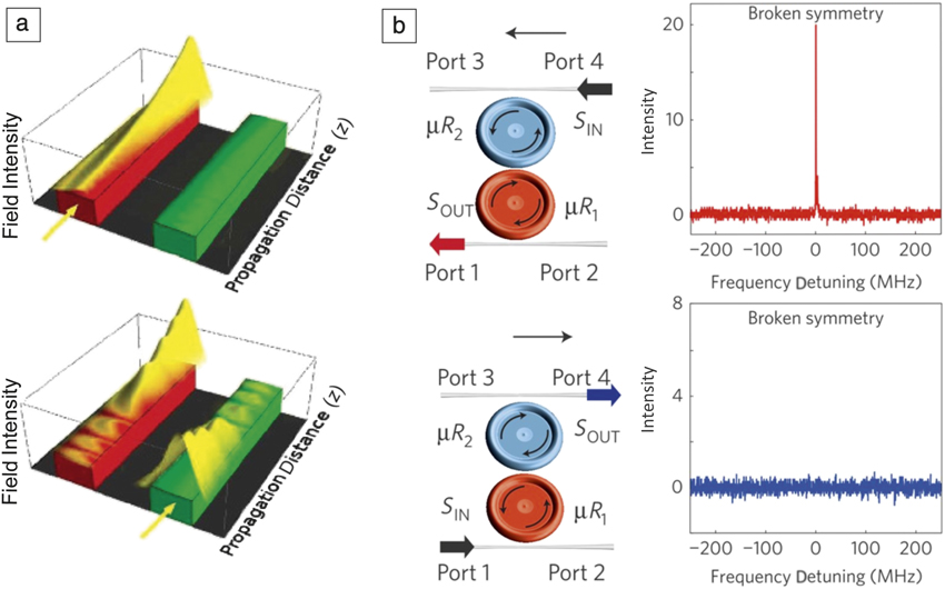
The properties of PT symmetric systems may be exploited to enhance the nonreciprocity arising from optical nonlinearity. Ramezani et al. were the first to propose combining PT symmetry with nonlinearity to build a nonlinear optical isolatorReference Ramezani, Kottos, El-Ganainy and Christodoulides37 (Figure 2a). Their system consists of two coupled waveguides containing balanced gain and loss, along with optical Kerr nonlinearity. When the Kerr nonlinearity exceeds a critical value, the coupled system behaves as an optical isolator—when light is injected into the active waveguide, the output from the passive one is zero (upper panel in Figure 2a), whereas for light injected into the passive waveguide, significant output is observed from the active waveguide (lower panel in Figure 2a). This system was studied in the PT unbroken phase, and it was found that the critical value of Kerr nonlinearity was reduced as the system approached the transition point. This work demonstrated that even though linear gain and loss do not themselves give rise to nonreciprocal light transport, they can strongly alter the effects of optical nonlinearity.
Nonlinear parity-time-reversal (PT) symmetric nonreciprocal optical devices. (a) Numerical simulation of light propagation in PT symmetric coupled nonlinear waveguides. For sufficiently strong nonlinearity, light always exits from the active waveguide (on the left), irrespective of the waveguide used for light injection. (b) Light propagation through PT symmetric coupled microcavity resonators (represented by μR 1 and μR 2), each coupled with an optical waveguide. The nonreciprocal effect enabled by the nonlinear gain saturation is enhanced by the field localization in the PT broken phase, resulting in substantial transmittance in one direction (upper plot) and near-zero transmittance in the reverse direction (lower plot). S IN and S OUT denote the input and output, respectively. (a) Adapted with permission from Reference Ramezani, Kottos, El-Ganainy and ChristodoulidesReference 37. © 2010 American Physical Society. (b) Adapted with permission from Reference Peng, Ozdemir, Lei, Monifi, Gianfreda, Long, Fan, Nori, Bender and YangReference 17. © 2014 Nature Publishing Group.

Another promising route toward PT symmetry-aided optical isolation is to make use of the asymmetric field distributions in the PT broken phase that can enhance nonlinear effects and subsequently reduce the operation threshold of a nonlinear optical isolator. Two groups have demonstrated ultralow-threshold nonlinear optical isolation in a pair of coupled optical microcavities with balanced gain and loss, where the passive microcavity is made of pure silica, and the active microcavity is made of erbium-ion-doped silica and can provide optical gain under optical pumpingReference Peng, Ozdemir, Lei, Monifi, Gianfreda, Long, Fan, Nori, Bender and Yang17,Reference Chang, Jiang, Hua, Yang, Wen, Jiang, Li, Wang and Xiao18 (Figure 2b). In these experiments, each microcavity was coupled to an input–output waveguide. Light was injected into the passive cavity, and the output at the second waveguide (coupled to the active cavity) was monitored. In the PT unbroken phase, the output exhibited a linear dependence on the input. In the PT broken phase, however, the input–output relation was nonlinear, due to enhanced nonlinear gain saturation arising from the concentration of a PT broken mode in the gain resonator. As a result, for light injected into the passive cavity, significant output was observed from the active cavity, whereas for light injected into the active cavity, the output at the passive cavity was near zero. The onset of nonreciprocal behavior can be shown to correspond precisely to the PT breaking transition.Reference Zhou and Chong38
Nonreciprocity via encircling EPs
As previously discussed, an EP is a point in parameter space (e.g., the space spanned by the coupling strength and frequency detuning of two coupled resonators) where a non-Hermitian degeneracy occurs—(at least) two eigenstates of the Hamiltonian, along with their associated eigenvalues, coalesce. This phenomenon cannot occur in Hermitian systems due to the spectral theorem of linear algebra.
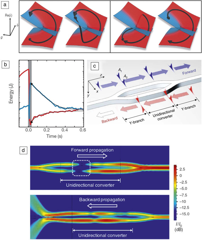
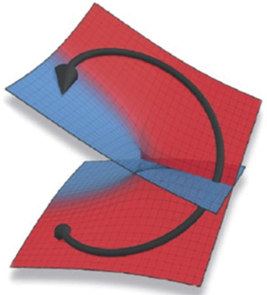
A pair of coupled resonators can be tuned to an EP by tailoring the frequency detuning, modal coupling, and losses. Near an EP, the complex eigenvalue surfaces take the form of two intersecting Riemann sheetsReference Heiss39 (the red and blue surfaces shown in Figure 3a), which merge at the EP. When a non-Hermitian system is driven along a closed parametric loop enclosing an EP, that is, encircling an EP in the parameter space, the eigenstates undergo a “state flip.” After one cycle, the initial eigenstate on the upper branch evolves continuously into the eigenstate on the lower branch, and vice versa. This phenomenon cannot be observed in a Hermitian system; when a Hermitian system is cycled around a Hermitian degeneracy point, each eigenstate always evolves continuously back to itself. The EP “state flip” has been demonstrated in microwave cavities,Reference Dembowski, Gräf, Harney, Heine, Heiss, Rehfeld and Richter40 “exciton-polariton billiards” with quantum wells embedded in optical microcavities,Reference Gao, Estrecho, Bliokh, Liew, Fraser, Brodbeck, Kamp, Schneider, Höfling, Yamamoto, Nori, Kivshar, Truscott, Dall and Ostrovskaya41 and holographic photonic lattices.Reference Hahn, Choi, Yoon, Song, Oh and Berini42
(a) Effects of dynamically encircling an exceptional point (EP). The vertical axis is the real part of the eigenvalue of the Hamiltonian, denoted Re(λ), and the horizontal axes are a 2D parameter space, where g and δ represent the coupling and detuning, respectively. Suppose the EP is encircled counterclockwise (left plots); if the system starts from the eigenstate on the lower branch (with smaller Re[λ]), it evolves continuously to the upper branch, but if it starts from the upper branch, it undergoes a sudden interbranch transition and cycles back to itself. The result is asymmetric mode conversion to the upper branch. If the EP is encircled in the opposite direction (right plots), the system undergoes asymmetric mode conversion to the lower branch. (b) Effect of dynamically encircling an EP in an optomechanical system. The cycling interval is indicated by gray shading; after encircling the EP, the energy in one mode (red curve) is transferred to the other mode (blue curve). (c) Schematic of a nonlinear device that uses EP encircling to achieve strongly nonreciprocal transmission. A 1,2 denotes the mode amplitude in each waveguide. (d) Numerical simulations of the fields in the proposed unidirectional converter; in the forward direction, the device allows ∼100% transmission (upper plot), while in the backward direction, transmission is suppressed by ∼10 dB, as the mode is incompatible with the Y-branch symmetry after propagating across the coupling region. The white dotted box in the upper panel highlights the nonadiabatic jump when dynamically encircling an EP. (a) Adapted with permission from Reference Doppler, Mailybaev, Böhm, Kuhl, Girschik, Libisch, Milburn, Rabl, Moiseyev and RotterReference 45. © 2016 Nature Publishing Group. (b) Adapted with permission from Reference Xu, Mason, Jiang and HarrisReference 31. © 2016 Nature Publishing Group. (c–d) Adapted with permission from Reference Choi, Hahn, Yoon, Song and BeriniReference 47. © 2017 Nature Publishing Group.

It is important to note, however, that the state flip phenomenon applies to the instantaneous eigenstates of the Hamiltonian, not the actual dynamical system state. For Hermitian systems, the adiabatic theorem states that if a system is initially an eigenstate of the Hamiltonian, slow parametric variations in the Hamiltonian induce the state to continuously “follow” the evolving eigenstate (up to a phase), so long as there is no nearby Hermitian degeneracy. For non-Hermitian systems, however, the adiabatic theorem does not hold.Reference Uzdin, Mailybaev and Moiseyev43 If an EP is encircled dynamically, the system state tends to follow the eigenstate with less loss; this means that if it was initially following the eigenstate with more loss, it can undergo an abrupt transition to the other eigenstate, even if the underlying parametric variation is slowReference Uzdin, Mailybaev and Moiseyev43 (Figure 3a).
An intuitive explanation for the breakdown of adiabaticity is as follows. When the system is driven along a trajectory corresponding to the eigenstate with more loss, it suffers from rapid decay. At the same time, a small amount of energy can be coupled to the other eigenstate, and this component grows exponentially (relative to the rest of the system state), and eventually dominates. Therefore, dynamically encircling an EP in the parameter space gives rise to “asymmetric mode switching”—the system state is transferred to one eigenstate, regardless of the initial conditions.
Asymmetric mode switching has recently been demonstrated in optomechanical and microwave devices. A silicon nitride membrane with two nearly degenerate vibrational eigenmodes was placed in an optical cavity and driven by a laser (via radiation pressure).Reference Xu, Mason, Jiang and Harris31 The laser power and detuning of the laser frequency relative to the cavity resonance were used as parameters for accessing and encircling an EP, where it was observed that the energy of one eigenmode was transferred to the other if the trajectory with less loss was selected (Figure 3b). If the EP was encircled in the opposite direction, the system ended up in its initial state. When the parametric variation is slow, the efficiency of the interstate energy transfer was found to depend only on the encircling direction. This can be regarded as an example of nonreciprocity induced by time modulation.Reference Sounas and Alù44
Another EP encircling experiment used lossy metallic waveguides.Reference Doppler, Mailybaev, Böhm, Kuhl, Girschik, Libisch, Milburn, Rabl, Moiseyev and Rotter45 For wave propagation along the waveguides, the axial coordinate plays the role of time, and changes in waveguide parameters (including loss engineering) are used to encircle the EP. In this configuration, the direction in which the light is injected (“forward” or “backward”) determines the direction of encirclement, and hence the direction of the asymmetric mode conversion. In other words, if light is injected in the “forward” direction, it is converted to one of the two waveguide modes; if injected in the “backward” direction, it is converted to the other waveguide mode, regardless of the initial choice of waveguide mode.Reference Ghosh and Chong46 However, optical reciprocity is not broken in this scheme, as the underlying optical medium is linear.
By combining EP-aided asymmetric mode conversion with nonlinearity, it is possible to realize a nonreciprocal on-chip device with extremely broad bandwidth. This was recently demonstrated theoretically using waveguides containing nonlinear (saturable) gainReference Choi, Hahn, Yoon, Song and Berini47 (Figure 3c–d). The waveguides are arranged in a simple configuration with a pair of Y-branches, and a pair of parallel coupled waveguides in the “coupling region” between the Y-branches. The EP-encircling is accomplished by varying the inter-waveguide widths and spacings (and hence the effective complex refractive indices of the coupled waveguides). The incident light, injected in either direction, is divided into two symmetric parts via a Y-branch, corresponding to an even mode of the coupled waveguides. The two coupled waveguides serve as a unidirectional converter: for the forward direction, the even mode preserves its symmetry when passing through the coupling region and transmits to the output waveguide; for the backward direction, the even mode is converted into an odd mode after passing through the coupling region, and is rejected by the second Y-branch waveguide due to modal incompatibility. In the linear gain regime, the device is reciprocal—although the even mode component in the backward case occupies a small percentage of the total power, the light propagating in the backward direction is subject to higher optical gain, so the transmission in both directions ends up being identical. However, at higher operating powers where gain saturation is substantial, reciprocity breaks down and a forward-to-backward transmission ratio of over 10 dB was observed, with nearly 100% forward transmission efficiency over a broad (∼100 THz) bandwidth.
Nonlinear topological photonics
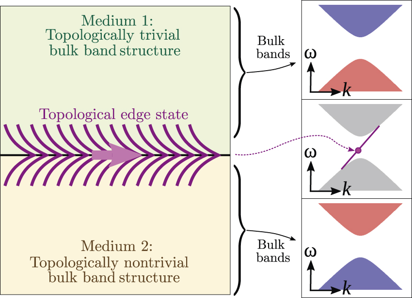
Another interesting direction in nonreciprocal photonics involves the combination of optical nonlinearity with “topological protection.” Topological photonics is a rapidly evolving field,Reference Lu, Joannopoulos and Soljačić8–Reference Ozawa, Price, Amo, Goldman, Hafezi, Lu, Rechtsman, Schuster, Simon, Zilberberg and Carusotto11 most of which lies outside the scope of this article. The central idea of topological photonics is to take the well-known analogy between conventional photonic crystals and electronic insulators,Reference Joannopoulos, Johnson, Winn and Meade48 and extend it to “topologically nontrivial” bands.Reference Haldane and Raghu49,Reference Raghu and Haldane50 Such nontrivial bands cannot be adiabatically deformed to a trivial band structure, just as a torus cannot be smoothly deformed into a sphere, and this “topological incompatibility” guarantees the existence of “topological edge states” at boundaries between trivial and nontrivial media (Figure 4). This phenomenon was first discovered in electronic fluids,Reference Bernevig and Hughes51 but within the past decade, there has been an explosion of research on topologically nontrivial band structures in photonics,Reference Lu, Joannopoulos and Soljačić8–Reference Ozawa, Price, Amo, Goldman, Hafezi, Lu, Rechtsman, Schuster, Simon, Zilberberg and Carusotto11 cold atom systems,Reference Aidelsburger, Atala, Lohse, Barreiro, Paredes and Bloch52 acoustics,Reference Yang, Gao, Shi, Lin, Gao, Chong and Zhang53,Reference He, Ni, Ge, Sun, Chen, Lu, Liu and Chen54 and mechanical lattices.Reference Huber55
Schematic illustrating how topological edge states arise at an interface between two media with topologically distinct band structures (ω, angular frequency; k, wave number). The purple lines illustrate the localization of the edge state to the interface.

The simplest topologically nontrivial band structure, the “Chern insulator,” occurs in two-dimensional (2D) crystals with broken time-reversal (T) symmetry (The T symmetry breaking in this case is due to a magnetic field rather than gain/loss, so the Hamiltonian remains Hermitian.) Its topological edge states have the special property of being unidirectional; the direction is determined by the sign of the T breaking. The first photonic demonstration of this used a microwave-scale lattice of magnetized ferrite rods.Reference Wang, Chong, Joannopoulos and Soljačić56,Reference Wang, Chong, Joannopoulos and Soljačić57 Due to the topological edge states, the lattice edge acted as an isolating waveguide with near-unity forward transmission and exponentially suppressed backward transmission, regardless of disorder, over the frequency range of the photonic bandgap.
It is difficult to use this design at optical frequencies, due to the weakness of magneto-optical effects. However, subsequent researchers have developed several different designs that can realize topologically nontrivial photonic bands at optical frequencies without using T-breaking materials.Reference Hafezi, Demler, Lukin and Taylor58–Reference Mittal, Fan, Faez, Migdall, Taylor and Hafezi61 These designs are necessarily reciprocal in the linear optics regime, but it is interesting to combine them with nonlinearity due to their potential for achieving disorder-robust nonlinear optical isolation.
The nonlinear topological photonic systems studied to date fall into two classes. The first considers nonlinear propagation dynamics such as self-focusing as a perturbation to an existing linear topological photonic model. The resulting phenomena can be interpreted in terms of the nonlinearity locally changing the system properties, such as inducing a defect or phase transition. In the second class of systems, a pump is used to induce a topological transition in the dynamics of a weak (linearized) probe beam (e.g., by mediating T-breaking parametric interactions). Both approaches offer interesting prospects for nonreciprocal photonics.
Waveguide arrays
Topological waveguide arrays can be fabricated either using traditional silicon photonics, or via laser writing into bulk media.Reference Szameit and Nolte62 Evanescent coupling between adjacent waveguides mimics quantum tunneling of particles between lattice sites, with the role of time played by the axial coordinate. This can be used to produce many single-particle lattice phenomena, including topologically nontrivial photonic band structures in one-dimension (1D)Reference Kraus, Lahini, Ringel, Verbin and Zilberberg63,Reference Verbin, Zilberberg, Lahini, Kraus and Silberberg64 and 2D,Reference Rechtsman, Zeuner, Plotnik, Lumer, Podolsky, Dreisow, Nolte, Segev and Szameit59,Reference Maczewsky, Zeuner, Nolte and Szameit65,Reference Noh, Huang, Leykam, Chong, Chen and Rechtsman66 as well as simulating higher-dimensional (e.g., four-dimensional) topological structures via parametric “synthetic dimensions.”Reference Zilberberg, Huang, Guglielmon, Wang, Chen, Kraus and Rechtsman67
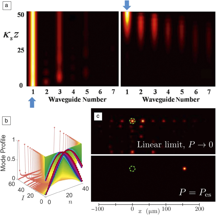
The simplest type of topologically nontrivial lattice in 1D is the Su–Schrieffer–Heeger (SSH) lattice.Reference Bernevig and Hughes51,Reference Su, Schrieffer and Heeger68 This is a T-symmetric lattice that exhibits topologically protected states localized to edges or domain walls. Proposals for achieving strong nonreciprocal response using this lattice are based on having the edge state only exist for one propagation direction. El-Ganainy and Levy have shown that this can be achieved by applying a magnetic garnet thin film to the edge waveguide.Reference El-Ganainy and Levy69 In the backward direction, the edge state’s propagation constant is shifted into resonance with bulk modes and it becomes delocalized, suppressing the backward transmission (Figure 5a).
(a) Numerical simulations showing nonreciprocity in a magneto-optical Su–Schrieffer–Heeger (SSH) lattice. Light injected in the forward direction (left panel) excites a topological edge state and remains strongly localized during propagation along direction z, while in the reverse direction (right panel), the edge state is shifted into resonance with bulk modes and diffracts away. (b) Emergence of solitonic edge states at high peak intensity (I) in a nonlinear SSH lattice, where n is the site number. (c) Numerical simulations showing the formation of a self-induced topological soliton at the critical input power P = P es, which moves unidirectionally along the edge of a 2D lattice, in a nonlinear waveguide array. (a) Reprinted with permission from Reference El-Ganainy and LevyReference 69. © 2015 OSA Publishing. (b) Reprinted with permission from Reference Hadad, Khanikaev and AluReference 70. © 2016 American Physical Society. (c) Reprinted with permission from Reference Leykam and ChongReference 75. © 2016 American Physical Society.

The previously discussed approach can be extended to nonlinear nonreciprocity using nonlinear lattices exhibiting a power-dependent edge state localization. Hadad et al.Reference Hadad, Khanikaev and Alu70,Reference Hadad, Vitelli and Alu71 studied nonlinear edge states in the SSH lattice, and showed that a nonlinear SSH lattice can undergo a “self-induced” topological transition. The lattice is topologically trivial at low powers, but at high powers, a robust nonlinear edge state emergesReference Hadad, Khanikaev and Alu70 (Figure 5b). This requires nonlinear intersite couplings that drive the system toward the phase boundary as the power increases.
Waveguide arrays can also be used to realize 2D topological lattices. Rechtsman et al. used laser-written helical waveguidesReference Rechtsman, Zeuner, Plotnik, Lumer, Podolsky, Dreisow, Nolte, Segev and Szameit59 to introduce effective T-breaking along the propagation axis. The two propagation directions (“forward” or “backward”) experience opposite T-breaking, and are decoupled if the waveguides are sufficiently smooth and vary slowly in the axial direction; the system as a whole is T-symmetric and reciprocal. Variant designs can exhibit topological transitions between conventional and topologically nontrivial behaviors by tuning the operating frequency or structural parameters.Reference Noh, Huang, Leykam, Chong, Chen and Rechtsman66,Reference Leykam, Rechtsman and Chong72
In the presence of optical nonlinearities such as the Kerr nonlinearities present in glass at high optical powers, the 2D lattices formed by waveguide arrays are predicted to exhibit topological solitons—self-focusing localized wave packets. Depending on the design parameters of the waveguide array, the solitons may circulate around a stationary point within the lattice,Reference Lumer, Plotnik, Rechtsman and Segev73 or move unidirectionally along the edge like the linear topological edge states (Figure 5c), including bypassing corners and defects.Reference Ablowitz, Curtis and Ma74,Reference Leykam and Chong75 The latter behavior distinguishes the 2D solitons from 1D edge solitons (which are always stationary), and may be interesting for signal processing applications (e.g., for routing solitons between different positions in a lattice).Reference Leykam and Chong75 To date, topological optical solitons have yet to be observed experimentally.
To achieve nonlinear optical isolation using solitonic edge states, one can combine the 1D or 2D topological lattice with asymmetric input–output coupling. This allows high-power signals to be transmitted along the waveguide array in the “forward” direction, mediated by the robust nonlinear edge state, while in the backward direction the power coupled into the array is insufficient to form a nonlinear edge state.Reference Zhou, Wang, Leykam and Chong76 In this scheme, the role of band topology is to provide a qualitative difference between the high-power and low-power modal profiles—similar to the role played by PT transitions, but without the effects of gain/loss.
Resonator lattices
A second platform for realizing topologically nontrivial photonic lattices is coupled optical resonators, which can be integrated into on-chip devices compatible with established semiconductor photonics technologies. The resonant light confinement allows for much stronger nonlinear effects compared to waveguide lattices.
The previously discussed 1D SSH model is simple to realize using lattices of resonating plasmonic or dielectric nanodisks; the effective intersite couplings, which tune the topological transition, can be controlled by varying the interresonator displacement. The SSH model edge states have been used to mediate nonreciprocal third-harmonic generation,Reference Kruk, Slobozhanyuk, Denkova, Poddubny, Kravchenko, Miroshnichenko, Neshev and Kivshar77 as well as disorder-robust lasing.Reference St-Jean, Goblot, Galopin, Lemaître, Ozawa, Le Gratiet, Sagnes, Bloch and Amo78–Reference Parto, Wittek, Hodaei, Harari, Bandres, Ren, Rechtsman, Segev, Christodoulides and Khajavikhan80 The nonlinear dynamics of these lasers and how they interact with the SSH topological transition are exciting topics to explore in the future.
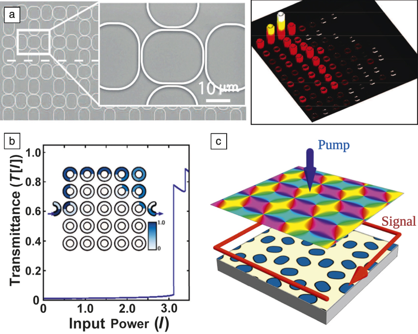
Topologically nontrivial 2D lattices have also been realized. This is accomplished by dividing the optical modes into two decoupled “sectors” (e.g., clockwise/anticlockwise ring resonator modes or left- and right-hand circular polarizations), such that T is effectively broken in each sectorReference Hafezi, Demler, Lukin and Taylor58,Reference Hafezi, Mittal, Fan, Migdall and Taylor60,Reference Mittal, Fan, Faez, Migdall, Taylor and Hafezi61 (Figure 6a). Similar to the forward and backward propagation sectors in waveguide arrays, the overall structure is T symmetric and reciprocal. For example, decoupled sectors can be realized via a bipartite lattice of ring resonators, such that clockwise modes in one sublattice couple to anticlockwise modes in the other sublattice, and vice versa. Such lattices can exhibit both conventional insulator and Chern insulator phases, with the topological transition driven by the resonator detunings or inter-resonator couplings.Reference Liang and Chong81–Reference Leykam, Mittal, Hafezi and Chong83
(a) Scanning electron microscope image of a topologically nontrivial 2D lattice of silicon ring resonators (left panel), and the spatially imaged topological edge states (right panel). (b) Numerical simulation of transmittance through a nonlinear coupled-resonator array, as a function of input power. The band structure is topologically nontrivial in the linear limit, so the transmittance is negligible at low powers. At high powers, the transmittance becomes large due to the emergence of a self-induced edge state (intensity plot shown inset). (c) Schematic of using a pump field (blue) in the form of a vortex lattice to induce a topological phase transition, creating a topological edge state for the signal (red) to propagate along. (a) Adapted with permission from Reference Hafezi, Mittal, Fan, Migdall and TaylorReference 60. © 2011 Nature Publishing Group. (b) Adapted with permission from Reference Zhou, Wang, Leykam and ChongReference 76. © 2017 IOP Publishing.

The nonlinear regime of topologically nontrivial 2D lattices is a subject of ongoing study. As in the waveguide case, topological transitions in these lattices can be driven by the nonlinearity. For example, an edge state can exist at high powers, but not at low powers, which may be useful for isolationReference Zhou, Wang, Leykam and Chong76 (Figure 6b). A novel feature of coupled cavity arrays is the ability to explore pump-induced topological phases, which can be based on incoherent tuning (e.g., using cross-phase modulation),Reference Leykam, Mittal, Hafezi and Chong83 or via coherent parametric interactions. The latter is particularly interesting because the system’s behavior becomes sensitive to the phase of the pump beam, which can be used to effectively break T symmetry and induce nonreciprocal edge states as linearized perturbations to the pump (Figure 6c).Reference Bardyn, Karzig, Refael and Liew84,Reference Sigurdsson, Li and Liew85 This approach is promising for nonreciprocal frequency conversion.Reference Peano, Houde, Brendel, Marquardt and Clerk86,Reference Peano, Houde, Marquardt and Clerk87
Outlook and conclusions
We have reviewed the role of non-Hermitian physics and band topology in designing nonlinear photonic devices, with a focus on enhancing nonreciprocal light transport. Although these two sets of phenomena have different origins, what they have in common is that by carefully managing the distribution of refractive index, loss, and/or gain, a transition among distinct different phases is induced (between PT unbroken and broken phases, or between topologically trivial and nontrivial band structures), and the qualitatively distinct mode behaviors in the two phases can enhance the reciprocity-breaking of an underlying nonlinear medium.
The results we have summarized point to a number of promising lines of future research. In topological photonics, for instance, crystalline symmetry-protected topological phases are now being implemented as photonic crystals,Reference Wu and Hu88–Reference Shalaev, Walasik, Tsukernik, Xu and Litchinitser91 which are extremely compact and could be coupled to resonant defects or atomsReference Barik, Karasahin, Flower, Cai, Miyake, DeGottardi, Hafezi and Waks90 to produce nonreciprocal or frequency-converting devices.Reference Peano, Houde, Brendel, Marquardt and Clerk86,Reference Peano, Houde, Marquardt and Clerk87,Reference Xu and Miroshnichenko92,Reference Yu, Chen, Hu, Xue, Yvind and Mork93 Another area of active research involves “topological polaritons,” which can be induced by circularly polarized optical pumping (which effectively breaks T).Reference Kartashov and Skryabin94,Reference Solnyshkov, Bleu and Malpuech95
Another highly promising direction is to combine the two concepts together (i.e., to explore non-Hermitian topological photonics). There are several pioneering works along this direction, including topological transitions in non-Hermitian waveguide arrays,Reference Zeuner, Rechtsman, Plotnik, Lumer, Nolte, Rudner, Segev and Szameit96 topologically protected modes based photonic limiters,Reference Kuhl, Mortessagne, Makri, Vitebskiy and Kottos97 and topological edge states in PT-symmetric quantum walks.Reference Xiao, Zhan, Bian, Wang, Zhang, Wang, Li, Mochizuki, Kim, Kawakami, Yi, Obuse, Sanders and Xue98 We anticipate that non-Hermitian topological photonics will provide a new route to control light transport as well as optical nonreciprocity.

Weijian Chen is a doctoral candidate in electrical and systems engineering at Washington University in St. Louis. He received his BS degree in optical information science and technology from the University of Science and Technology of China in 2012, and his MS degree in electrical engineering from Washington University in St. Louis in 2015. His current research interests include high-quality optical microcavities, non-Hermitian optics, optical sensing, and quantum light sources. Chen can be reached by email at wchen34@wustl.edu.

Daniel Leykam leads a junior research team at the Institute for Basic Science, South Korea, where he is supported by a Young Science Fellowship. He completed his PhD degree in 2015 at the Nonlinear Physics Centre at The Australian National University, and then worked as a postdoctoral fellow at Nanyang Technological University, Singapore, for two years. Leykam can be reached by email at dleykam@ibs.re.kr.

Yidong Chong joined Nanyang Technological University, Singapore, as an assistant professor in 2012. He received his BSc degree in physics from Stanford University in 2003, and his PhD degree in physics from the Massachusetts Institute of Technology in 2008. From 2008 to 2012, he was a postdoctoral researcher at Yale University. His research interests include topological photonics, non-Hermitian photonics, and random optical media. Chong can be reached by email at yidong@ntu.edu.sg.

Lan Yang is the Edwin H. and Florence G. Skinner Professor in the Department of Electrical and Systems Engineering at Washington University in St. Louis. She received her BS degree from the University of Science and Technology of China, and her PhD degree in applied physics from the California Institute of Technology in 2005. She is the recipient of a 2010 Presidential Early Career Award for Scientists and Engineers. She is a Fellow of The Optical Society. Her research interests include optical microcavities, non-Hermitian photonics, lasers, sensing, and imaging. Yang can be reached by email at yang@seas.wustl.edu.