1. Introduction
An exoskeleton robot is a type of human–robot cooperative system designed to be worn on the body, enabling direct physical interaction during operation, so as to realize the seamless combination of the powerful driving ability of the robot and the developed intelligence of the human body [Reference Niu, Guo, Song, Wu and Qu1, Reference Danaish, Han, Xu, Baig, Dong, Gao and Xu2]. The upper limbs are involved in a wide variety of daily activities, most of which require complex movements of the shoulders. Given that there are multiple joints in the shoulder complex, its movement is the result of the combination of all joints [Reference Jorgensen, Hakansson and Desai3]. The motion structure design of the shoulder complex is a key design requirement for the construction of exoskeletons. In particular, two things need to be taken into account. First, the kinematic function of the shoulder complex must provide a full range of motion. Second, it should not cause any discomfort to the wearer of the exoskeleton during operation. In previous shoulder exoskeleton designs, the shoulder joint was typically modeled as a spherical joint to provide three degrees of freedom (DOF) centered at the glenohumeral joint: abduction–adduction, flexion–extension, and internal-external rotation [Reference Castro, Rasmussen, Andersen and Bai4, Reference De Bock, Ampe, Rossini, Tassignon, Lefeber, Rodriguez-Guerrero, Roelands, Geeroms, Meeusen and De Pauw5]. However, the complex movement of the shoulder joint is a composite movement of all three joints, namely the glenohumeral (GH) joint, the acromioclavicular (AC) joint, and the sternoclavicular (SC) joint [Reference Fayad, Hoffmann, Hanneton, Yazbeck, Lefevre-colau, Poiraudeau, Revel and Roby-Brami6]. Poor coordination of movements may lead to central dysfunction of the humerus head, resulting in secondary shoulder mismatch, resulting in deviations between the rotational axis of the mechanical joint and that of the human joint during movement, resulting in additional mechanical constraints, and ultimately resulting in shoulder pain and joint injury [Reference Haarman, Hekman, Haalboom, Van Der Kooij and Rietman7]. Shoulder joint mismatch is a fundamental biomechanical dysfunction characterized by abnormal displacement of the humeral head relative to the glenoid fossa, impairing its ability to maintain centered rotation during movement. This condition primarily stems from muscular imbalances, notably weakness in the rotator cuff muscles, such as the infraspinatus, which are unable to adequately depress the humeral head. Consequently, during arm elevation, the dominant pull of the deltoid muscle superiorly displaces the humeral head, leading to pathological superior migration.
To enhance wearing comfort, an exoskeleton must align its rotational axis with the anatomical axis of the human joint. Current compensation methods primarily include manual alignment [Reference Beil and Asfour8–Reference Esquenazi, Talaty, Packel and Saulino10], kinematic redundancy [Reference Schiele and Van Der Helm11–Reference Naf, Koopman, Baltrusch, Rodriguez-Guerrero, Vanderborght and Lefeber13], soft exoskeleton [Reference Phan, Thai, Hoang, Lovell and Do14–Reference Zhou, Hohimer, Young, McCann, Pont-Esteban, Civici, Jin, Murphy, Wagner, Cole, Phipps, Cho, Bertacchi, Pignataro, Proietti and Walsh16], compatible elements [Reference Lee, Kim, Lee, Lee, Choi, Kim, Park and Choi17, Reference Machekposhti, Tolou and Herder18], spherical new parallel mechanism [Reference Hunt, Lee and Artemiadis19, Reference Hsieh, Chen, Chien and Lan20], and rigid-flexible coupling [Reference Kim, Jeong and Kong21–Reference Vatan, Nefti-Meziani, Davis, Saffari and El-Hussieny23]. Among these, manual alignment suffers from low accuracy and requires repetitive adjustments before each use, heavily relying on human intervention. Kinematic redundancy, the most common passive compensation method, exhibits instability under load. While soft exoskeletons improve comfort, their lack of rigid support compromises power transmission efficiency. Compatible elements passively adapt to joint mismatch through flexibility, but generate undesired torque, necessitating additional actuators for compensation. Spherical parallel mechanisms, advantageous for compactness and high stiffness in shoulder exoskeletons, struggle to address joint mismatch at the control level due to structural constraints. In contrast, rigid-flexible coupling combines rigid support with flexible adaptability, simultaneously meeting power and comfort requirements in exoskeleton design.
While prior research has often addressed kinematic mismatch through structural compensation mechanisms, a more holistic approach that integrates control strategies is essential for optimally balancing exoskeleton assistance and user comfort. In recent years, several works have begun to explore variable stiffness actuation to improve compatibility and comfort. Yang developed a cable-driven elbow exoskeleton featuring a variable stiffness actuator, enabling natural motion assistance and improved joint compliance during rehabilitation exercises [Reference Yang, Zhang and Fu24]. Zhang demonstrated that an unpowered hip exoskeleton mimicking the hip’s variable stiffness can reduce human walking metabolic cost by about 9 % [Reference Zhang, Li, Zhang, Zhou, Chen and Xiong25]. Zhu designed a passive shoulder exoskeleton driven by a variable stiffness mechanism torque generator, integrating adjustable torque curves while maintaining a lightweight structure [Reference Zhu, Balser, Shen and Bai26]. Zhou demonstrated the value of variable stiffness in enhancing wearing comfort and matching, emphasizing mechanical adaptability and ergonomic alignment between the device and human limb [Reference Zhou, Shao, Shi, Feng, Ding and Zhang27]. The above research demonstrates the significance of variable stiffness elements in addressing mismatch issues and enhancing the comfort of human wearing. In this work, we simultaneously co-design the compensation structure and the control architecture, aiming to resolve scapulohumeral rhythm mismatch via an integrated framework of mechanical compensation and variable stiffness control. The proposed mechanism inherently embodies variable stiffness properties, thereby intrinsically supporting this dual approach and facilitating more natural and comfortable motion assistance. This paper is organized as follows: The second section studies and analyzes the kinematics of the shoulder joint, and obtains the relevant data on the need for mismatch compensation. In the third section, a shoulder exoskeleton with mismatch compensation is proposed based on demand, and the compensation mechanism is analyzed. In the fourth section, while solving the mismatch problem, the human–machine coupling model is established to evaluate the assisting effect of the exoskeleton. Section five draws conclusions.
2. Shoulder kinematics
The scapular complex, composed of the humerus, scapula, and clavicle, includes three main joints: the GH joint, the AC joint, and the SC joint [Reference Lenarcic and Stanisic28], as illustrated in Figure 1. The GH joint serves as the rotational center between the humerus and the scapula. The AC joint facilitates rotation between the scapula and the clavicle, while the SC joint enables motion between the clavicle and the sternum.
The center of the shoulder, glenohumeral joint (CGH) describes the rotation of the humerus around the scapula.

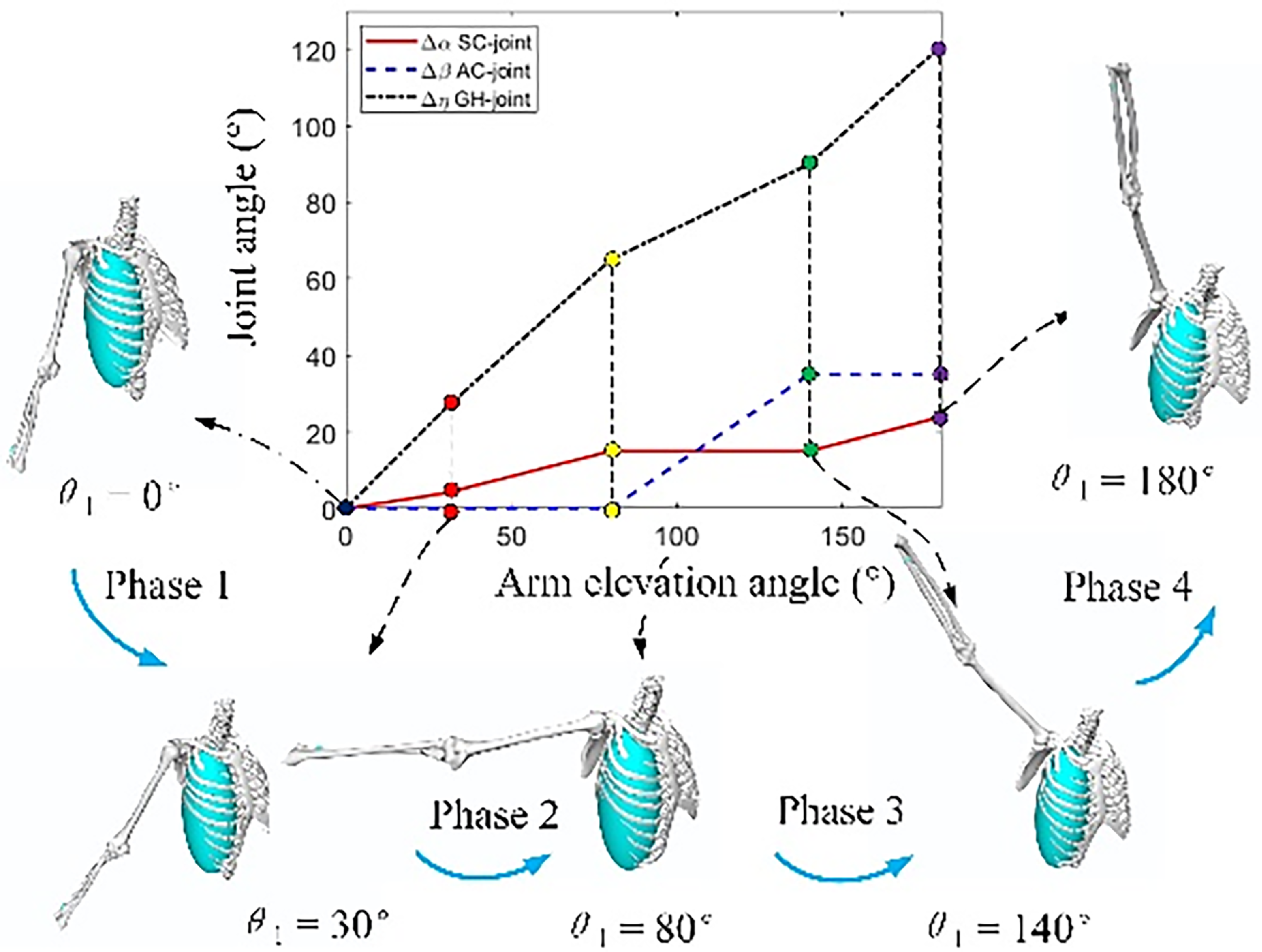
The natural movement of the shoulder complex involves the coordinated motion of all its constituent joints. For instance, achieving 180°of arm elevation requires contributions from both the humerus and scapula: the humerus provides approximately 120° of motion, while the scapula contributes the remaining 60° [Reference Seth, Matias, Veloso, Delp and Ren29]. This coordinated interaction between the humerus and scapula is known as scapulohumeral rhythm, as illustrated in Figure 2. The process is typically divided into four phases. During the initial phase, rotation occurs primarily at the GH joint. In the second phase, movement takes place around both the GH and SC joints. The third phase is dominated by rotation of the scapula around the AC joint, and the final phase is again characterized primarily by GH joint rotation. In other words, the shoulder has five DOF and has two centers of rotation (CoR). The first is the CoR of the torso (TCoR), which consists of the SC joint, the AC joint, and the scapulothoracic joint, which produce two types of shoulder joint movements: elevation-compression and extension-contraction. The second is at the center of rotation of the shoulder (SCoR), which is the center of rotation of the GH joint. This gives rise to three arm movements: flexion–extension, abduction–adduction, and internal and external rotation.
Four stages of scapulohumeral rhythm (Data source: reference 21).
These arm movements are produced by various redundant muscles, some of which produce shoulder movements at the same time. As a result, some movements cause changes in SCoR, making the mechanical center of rotation (MCoR) inconsistent with the SCoR. This misaligned drive applies force in an undesired direction, which can lead to reduced exoskeleton performance and risk of joint or skin damage [Reference Have, Rossini, Rodriguez-Guerrero, Van Rossom and Jonkers30].
The mathematical model of the shoulder joint can be described as:
 \begin{align} \left(\begin{array}{l} x_{CGH}\\ y_{CGH}\\ z_{CGH} \end{array}\right)=\left(\begin{array}{l} f\left(\theta _{1},\theta _{2},\theta _{3},h,m_{ext}\right)\\ g\left(\theta _{1},\theta _{2},\theta _{3},h,m_{ext}\right)\\ h\left(\theta _{1},\theta _{2},\theta _{3},h,m_{ext}\right) \end{array}\right) \end{align}
where
 $\theta _{1}$
is arm elevation angle;
 $\theta _{2}$
is elevation plane;
 $\theta _{3}$
is Internal and external shoulder rotation angle;
 $h$
is Body height;
 $m_{ext}$
is external load. Here, we make a simplified assumption:
-
(1) The additional external load does not affect the position of the scapula;
-
(2) The internal and external rotation angle
 $\theta _{3}$
of shoulder joint does not affect the position of CGH joint;
-
(3) The relative motion of the CGH joint is independent of the elevation plane
$\theta _{2}$
.


For example, for abduction–adduction:
 \begin{align} \left(\begin{array}{l} x_{CGH}\\ y_{CGH} \end{array}\right)=\left(\begin{array}{l} f\left(\theta _{1},h\right)\\ g\left(\theta _{1},h\right) \end{array}\right)=\left(\begin{array}{l} f\left(\theta _{1}\right)\\ g\left(\theta _{1}\right) \end{array}\right)\frac{h}{h_{ref}} \end{align}
Then, the expression of shoulder-humeral rhythm is as follows:
 \begin{align} \left(\begin{array}{l} x_{CGH}\\ y_{CGH} \end{array}\right)=\left(\begin{array}{l} -l_{c}\cos \left(\alpha -90\right)+l_{s}\sin \left(\beta +\alpha \right)\\ l_{c}\sin \left(\alpha -90\right)+l_{s}\cos \left(\beta +\alpha \right) \end{array}\right)\frac{h}{h_{ref}} \end{align}
where
 $\alpha$
is SC joint angle;
 $\beta$
is AC joint angle;
 $\eta$
is GH joint angle;
 $l_{c}$
is collarbone length;
 $h_{ref}$
is refer to body height.
The kinematics of the shoulder joint were analyzed in reference [Reference Nef and Riener31]. It is worth noting that the above calculation obtained two-dimensional data of the rotation center of the shoulder joint, which was not comprehensive and accurate enough. Here, in order to be more realistic and accurate, combined with the data of shoulder joint rotation center during abduction–adduction and flexion–extension in OpenSim human motion simulation software [Reference Delp, Anderson, Arnold, Loan, Habib, John, Guendelman and Thelen32], the three-dimensional trajectory of shoulder joint rotation center was obtained, as shown in Figure 3. The data of the shoulder joint rotation center are shown in Table I.
Scapulohumeral rhythm track.

Data of shoulder joint rotation center.

Once the movement trajectory of the SCoR is known, one way to solve the mismatch problem is to find a movement mechanism that replicates this movement as much as possible, thereby reducing the average distance between the rotation center of the human shoulder joint and the rotation center of the mechanical actuator. The other is to detect the alignment. Reference [Reference Park, Toxiri, Chini, Natali, Caldwell and Ortiz33] uses an encoder to measure the arm’s connecting rod angle and compares it with the arm elevation angle measured by the motion capture system in order to evaluate the mismatch error. If MCoR is ideally aligned with SCoR, the arm link is parallel to the arm. Therefore, in the ideal case, the angle ratio is 1, because the arm link and the arm have the same angle. In this paper, the motion pair and the shoulder-humeral adjuster are used to compensate for the mismatch.
3. Shoulder exoskeleton with mismatch compensation capability
This paper proposes a shoulder exoskeleton based on a winding mechanism (SEBOWM) with mismatch compensation capability, designed to enhance upper-limb mobility and improve wearing comfort. The system employs a line-driven actuation approach in which high-tensile cables transmit mechanical power from the back-mounted actuator unit to the primary and secondary boosters located near the shoulder joint, as depicted in Figure 4. This shoulder exoskeleton system adopts a highly integrated design, with a total designed weight of 3.5 kilograms. It is equipped with a complete embedded power supply and computing unit, eliminating the need for external device support. The system’s comprehensive design in terms of lightweight and motion coordination fully takes into account its high portability in daily use. Exoskeletons, with their wireless operation capabilities and ergonomic support structures, enable wearers to wear them quickly. The SEBOWM consists of a lightweight exoskeleton frame made of carbon fiber-reinforced polymer to ensure strength while minimizing inertia. Five revolute (R) joint pairs, strategically arranged to accommodate the shoulder’s three DOF: flexion–extension, abduction–adduction, internal-external rotation. A two-level power collocation system, comprising: Primary Booster: handles high-torque demands during strenuous motions (such as lifting heavy objects). Secondary Booster: provides fine-tuned assistance for precise, low-force movements, such as reaching or positioning.
SEBOWM schematic diagram.

The mismatch compensation mechanism in the SEBOWM utilizes a spring-loaded cable tensioning system that automatically adjusts slack to prevent cable disengagement during dynamic movements, enabling real-time kinematic adaptation during shoulder motion as illustrated in Figure 5. The SEBOWM operates via tendon-driven actuation, where motorized spools wind/unwind cables to generate joint torque. The back-mounted actuator drives cables through low-friction pulley systems, distributing force between the primary and secondary boosters based on real-time torque requirements. Two-Level Power adaptation: for high-power tasks, the primary booster engages, maximizing torque output. For precision tasks, the secondary booster provides smoother, more controlled assistance. Cable Slack Prevention: An integrated tension sensor continuously monitors cable tightness, with a dynamic winding mechanism adjusting in real time to prevent slack and maintain efficient force transfer. This design ensures high-power transmission efficiency while addressing common challenges in tendon-driven exoskeletons, such as cable relaxation and misalignment. By combining multi-DOF kinematics with adaptive power distribution, the SEBOWM offers a robust solution for both assistive and rehabilitative applications. Based on the winding device, a CoR tracking mechanism (CoRT) is designed to compensate for the vertical deviation caused by SHR. The CoRT mechanism adjusts the trajectory of the MCoR according to the elevation angle of
 $\theta _{1}$
to ensure that the SCoR and MCoR are aligned and solve the mismatch caused by shoulder-humeral rhythm. A level compensation mechanism is designed to compensate for the joint mismatch caused by the horizontal movement of the upper arm. The horizontal compensation mechanism consists of a passive moving secondary joint and a rotating joint, which naturally aligns the MCoR with the SCoR in the horizontal plane. The guide rail is specifically designed to compensate for the mismatch occurring during shoulder extension movements.
SEBOWM mismatch compensation diagram.

To meet the motion requirements of the shoulder joint exoskeleton, the SEBOWM has a scapulohumeral rhythm compensation mechanism which has three motion states, as shown in Figure 6. State A is the initial state of the scapulohumeral rhythm compensation mechanism. The moving platform has a motion of three DOF, and the moving platform is located at the upper boundary of the vertical movement direction. In State B, the spring is compressed due to tension in the winding rope, and the moving platform is located at the lower boundary of the direction of movement. The motion constraint of the mechanism is affected by the tension of the winding rope. State C is for passively adapting to the mismatch that occurs during the movement of the shoulder joint.
Kinematics of the scapulohumeral rhythm compensation mechanism.

The mathematical models of the SCoR and the MCoR were established, as shown in Figure 7. Among them, the rotation center locus of the shoulder joint in the process of shoulder joint flexion–extension and abduction–adduction movement has been given previously, as shown in Figure 3.
Mismatch compensation schematic.

The exoskeleton mechanism is simplified into one moving pair, three rotating pairs, and a scapulohumeral rhythm compensation mechanism. The expectation is that the MCoR trajectory can replicate or best fit the SCoR trajectory to achieve joint alignment. It can be expressed as follows:
 \begin{align} C=\sqrt{\sum _{i=1}^{n}\frac{\left(x_{\mathrm{MCoR},i}-x_{\mathrm{SCoR},i}\right)^{2}+\left(y_{\mathrm{MCoR},i}-y_{\mathrm{SCoR},i}\right)^{2}+\left(z_{\mathrm{MCoR},i}-z_{\mathrm{SCoR},i}\right)^{2}}{\left(n\right)}} \end{align}
where
 $x_{\mathrm{MCoR},i},y_{\mathrm{MCoR},i},z_{\mathrm{MCoR},i}$
represent the MCoR and SCoR coordinates of different angles, respectively.
Take the body wear center as the coordinate origin, and establish a three-dimensional coordinate system:
The x direction compensation is affected by moving pairs
 $P$
, rotating pairs
 $R_{1} , R_{2} , R_{3}$
, and scapulohumeral rhythm compensation
 $L_{\mathrm{shrx}}$
and the expression of MCoR along the x direction is obtained:
 \begin{align} x_{\mathrm{MCoR}}=P+L_{0}\cos \left(R_{1}\right)+\left(L_{1}\cos \left(R_{2}\right)+L_{2}\right)\cos \left(R_{3}\right)+L_{\mathrm{shrx}} \end{align}
The y direction compensation is affected by rotation pairs
 $R_{1} , R_{2} , R_{3}$
, and shoulder-humeral rhythm compensation
 $L_{\mathrm{shry}}$
, and the expression of MCoR along the y direction is obtained:
 \begin{align} y_{\mathrm{MCoR}}=L_{0}\sin \left(R_{1}\right)+\left(L_{1}\cos \left(R_{2}\right)+L_{2}\right)\sin \left(R_{3}\right)+L_{\mathrm{shry}} \end{align}
The rotation pairs
 $R_{1}$
and
 $R_{2}$
and the scapulohumeral rhythm compensation
 $L_{\mathrm{shrz}}$
affected the z direction compensation, and the expression of MCoR along the z direction was obtained:
 \begin{align} z_{MCo\mathrm{R}}=\left(L_{0}\cos \left(R_{1}\right)+L_{1}\right)\sin \left(R_{2}\right)+L_{\mathrm{shrz}} \end{align}
where
 $x_{\mathrm{MCoR}},y_{\mathrm{MCoR}},z_{\mathrm{MCoR}}$
represent the mechanical rotation center;
 $L_{i}(;i=1,2,3);$
, respectively, represent the distance between the moving pairs;
 $R_{i}(;i=1,2,3);$
, respectively, represent the rotation angle of the rotating pair;
 $P$
represents the distance of the moving pair.
 $L_{\mathrm{shrx}},L_{\text{shry}},L_{\text{shrz}}$
, respectively, represent the compensation distance in the direction of the shoulder and scapulohumeral rhythm compensation mechanism.
To sum up, the MCoR expression is as follows:
 \begin{align} \left\{\begin{array}{l} x_{\mathrm{CoR}}=P+L_{0}\cos \left(R_{1}\right)+\left(L_{1}\cos \left(R_{2}\right)+L_{2}\right)\cos \left(R_{3}\right)+L_{\mathrm{shrx}}\\ y_{\mathrm{CoR}}=L_{0}\sin \left(R_{1}\right)+\left(L_{1}\cos \left(R_{2}\right)+L_{2}\right)\sin \left(R_{3}\right)+L_{\mathrm{shry}}\\ z_{\mathrm{CoR}}=\left(L_{0}\cos \left(R_{1}\right)+L_{1}\right)\sin \left(R_{2}\right)+L_{\mathrm{shrz}} \end{array}\right. \end{align}
As shown in Figure 8, the mismatch compensation space includes SCoR’s motion trajectory of abduction–adduction and flexion–extension. After wearing the exoskeleton, the joint mismatch problem can be resolved by adjusting the values of
 $P , R_{1} , R_{2} , R_{3} , L_{\mathrm{shrx}},L_{\text{shry}},L_{\text{shrz}}$
Among them, the motion pairs
 $P , R_{1}$
, and
 $R_{3}$
are passively adapted when the freedom of human motion is satisfied. In contrast, the motion pair
 $R_{2}$
and
 $L_{\mathrm{shrx}} , L_{\mathrm{shry}}$
, and
 $L_{\mathrm{shrz}}$
can be active and passive. In addition to mismatch compensation, the motion pair
 $R_{2}$
and
 $R_{5}$
are also guaranteed to provide power, the changes of
 $L_{\mathrm{shrx}} , L_{\mathrm{shry}}$
, and
 $L_{\mathrm{shrz}}$
were related to the variable stiffness control of scapulohumeral rhythm.
Mismatch compensation space.

To improve the comfort of the human body, we adopt the layered mismatch compensation strategy. A wide range of misalignments is compensated by a combination of back and arm rails and multiple rotating pairs. For minor misalignments, it is clear that large compensation is not desirable. Based on the winding mechanism, we designed a scapulohumeral rhythm compensation mechanism suitable for small-range mismatch compensation, as shown in Figure 9. The scapulohumeral rhythm compensation mechanism is composed of two parts. The drive module includes a fixed support column, a drive motor, and a gear. The winding module mainly includes an elastic rod, a spring, a fixed platform, a moving platform, and a winding rope. The moving platform is firmly connected to the driving gear, and the winding is completed by the motor rotation. The existence of the spring can achieve a small range of telescopic and bending motion, and passive compensation of joint mismatch. Notably, the preload on the spring between the elastic rods varies during winding, enabling the mechanism to exhibit variable stiffness.
Scapulohumeral rhythm compensation mechanism.

To verify the compensation effect of the scapulohumeral rhythm compensation mechanism, a wearable simulation was carried out, as shown in Figure 10. Among them, Figure 10(a) and 11(c) show shoulder flexion–extension and abduction–adduction movements, respectively. Figure 10(b) shows the adjustment process of the scapulohumeral rhythm compensation mechanism during shoulder abduction–adduction, and flexion–extension. The existence of elastomer elements makes up for the lack of large-range compensation accuracy of the motion pair of the shoulder exoskeleton mechanism and realizes millimeter-level passive compensation of joint mismatch through small-range telescopic and bending motion. Importantly, the spring displacement remains within the shoulder joint’s kinematic range, as analyzed in Section 2, in which the mismatch compensation of the abduction–adduction direction is maximum 44 mm, and the mismatch compensation of the flexion–extension direction is maximum 57 mm, which realizes the passive mismatch compensation of the shoulder joint during movement to a certain extent.
Mismatch compensation of scapulohumeral rhythm compensation mechanism.

Opensim man-machine model.

4. Biomechanical simulation of OpenSim
The essence of the powered exoskeleton is to provide help to personnel; so, it is necessary to ensure the power performance of the exoskeleton and reduce the muscle burden of the wearer while solving the mismatch problem. In this paper, under OpenSim, the established exoskeleton robot model was exported into an XML format document, the code was modified by the Notepad++ programming environment, and the coupling modeling of the shoulder joint exoskeleton and human musculoskeletal model was completed. It is worth noting that since flexion–extension is not a degree of freedom in the OpenSim software, we use the elevation plane angle moment as the flexion moment here. In order to evaluate the assisting performance of the shoulder exoskeleton, the muscle force of the anterior deltoid (blue), the medial deltoid (yellow), and the posterior deltoid (green), which are related to the motion of the shoulder joint, and the shoulder joint torque are selected as evaluation indicators [Reference Seth, Dong, Matias and Delp34], as shown in Figure 11.
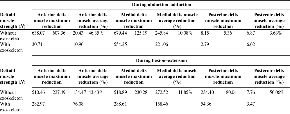
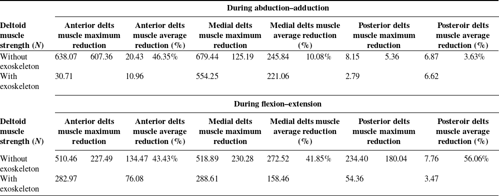
To make a more intuitive comparison of the role of the exoskeleton in power assistance, a simulation comparison was conducted with or without the exoskeleton, and the results are shown in Figure 12. The analysis showed that after wearing the shoulder exoskeleton, the deltoid muscle force was significantly reduced in both flexion–extension and abduction-adduction processes, and the maximum reduction was 607.36 n (95.18 %). Among them, in the process of abduction–adduction exercise, the muscle force of the anterior deltoid was significantly reduced, with an average reduction of 46.35 %, while in flexion–extension exercise, the muscle force of the anterior deltoid, the medial deltoid, and the posterior deltoid were significantly reduced, with an average reduction of 43.43 %, 41.85 %, and 56.06 %. It is worth noting that the muscle force of the front deltoid does not provide support in the early stage of shoulder joint movement, and the average muscle force in the whole exercise process is lower than that of the other two muscles, while the side deltoid has the highest participation in the exercise process. Specific data analysis results are shown in Table II.
Comparative analysis of deltoid muscle strength wearing exoskeleton.
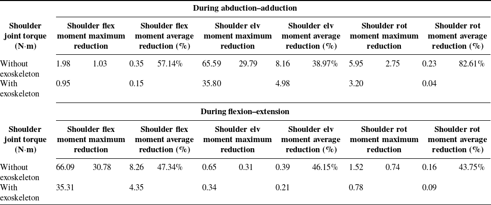
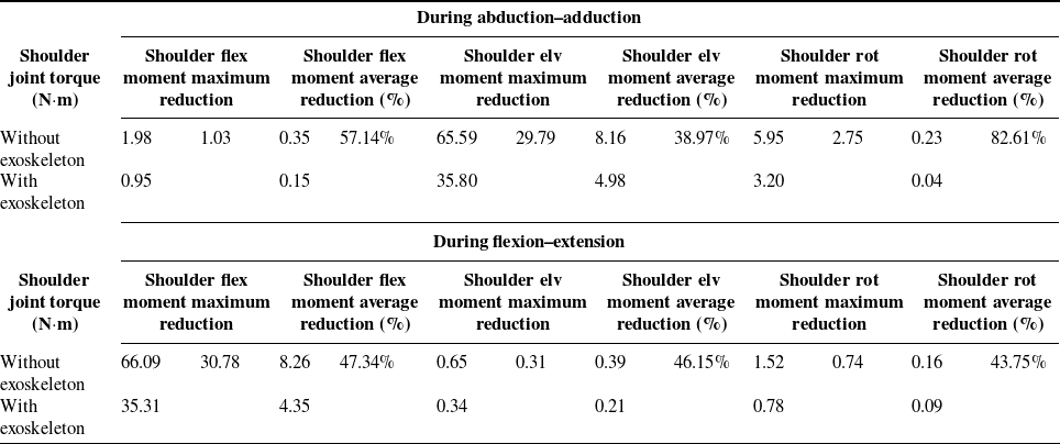
Comparative analysis of shoulder joint torque wearing exoskeleton.
Comparison of muscle strength with or without wearing exoskeleton.

In addition to the muscle force evaluation of the deltoid muscle of the shoulder joint, the moment of the shoulder joint is also an important evaluation index to measure the help of the exoskeleton. Figure 14 shows the comparison of the moment of the shoulder joint with or without the exoskeleton. The analysis shows that after wearing the shoulder exoskeleton, each torque of the shoulder joint is significantly reduced, indicating the effectiveness of the shoulder exoskeleton. In addition, the maximum reduction of shoulder elv moment torque was 29.7 N·m, and the average reduction of shoulder rot moment was 82.61 %. In the shoulder flex moment direction, the shoulder joint torque decreases by 30.78 N·m at the maximum, and the joint torque decreases by more than 40% in all directions. Elv stands for elevate, and rot stands for rotation. Detailed data analysis results are shown in Table III. In the abduction–adduction movement, R2 mainly provides assistance. In flexion–extension, R5 mainly provides power, while R2 only provides secondary assistance. It is worth noting that shoulder flex moment during adduction and abduction is the same height as shoulder elv moment during flexion–extension, indicating that, to some extent, the adduction direction of shoulder joint adduction–extension direction during flexion–extension are mirror images of each other. The internal and external rotation torque of the shoulder joint shows the same value, the same trend, and the opposite direction due to the change of direction in the process of abduction–adduction and flexion–extension.
Central locus plane of shoulder joint.

Comparison of shoulder joint torque during abduction–adduction and flexion–extension.

Based on the simulation results, our analysis from both deltoid muscle force generation and shoulder joint torque perspectives demonstrates that the designed exoskeleton provides measurable assistance. Both flexion–extension and abduction–adduction exercises can effectively reduce the generation of deltoid muscle force and shoulder joint torque, which proves the effectiveness of shoulder joint exoskeleton design. At the same time, it provides an important reference for further revealing the biomechanical characteristics of human shoulder joint physiology and assisting in the design of shoulder joint exoskeleton robots.
5. Conclusion
This study proposes a novel SEBOWM to address the kinematic mismatch caused by the complex motion of the shoulder joint. Through quantitative analysis of shoulder kinematics, the maximum displacement compensation requirements were identified as 66.35 mm in abduction–adduction and 61.68 mm in flexion–extension. The proposed design introduces dual compensation strategies: a wide-range passive mechanism employing moving and rotating pairs with guide rails, and a precision winding-based adjuster enabling millimeter-level alignment. Simulation results indicate that the shoulder–humerus adjuster achieves 44 mm compensation in abduction–adduction and 57 mm in flexion–extension, effectively reducing joint mismatch during motion. OpenSim simulations further validated the assistive capability of the exoskeleton. The deltoid muscle force was reduced by up to 95.18 %, and shoulder joint torque decreased by more than 40 % across motion directions.
In summary, the SEBOWM effectively mitigates shoulder joint kinematic mismatch while providing substantial power assistance. These findings demonstrate its strong potential for shoulder rehabilitation, human performance augmentation, and future integration into intelligent wearable robotic systems. Although the proposed shoulder exoskeleton shows promising performance, several modeling limitations should be acknowledged. Future work should focus on developing more realistic and personalized shoulder models, integrating medical imaging data and flexible multi-body dynamics to improve simulation accuracy. Co-simulation with platforms such as ROS or Gazebo could better represent contact mechanics and elastic behavior in human exoskeleton systems. In addition, experimental validation using in vivo data from wearable sensors or dynamic imaging will be essential to enhance model reliability and guide future design optimization.
Author contribution
LN wrote the manuscript; SG, XY, HQ, MS, and XY assisted with sampling and laboratory analyses. All authors read and approved the final manuscript.
Financial support
This work was supported by National Natural Science Foundation of China (Grant No. 52275004), Shenzhen Medical Research Fund D2401008, Beijing Natural Science Foundation of China (Grant No. 3242012).
Competing interests
The authors declare no competing financial interests.
Ethical approval
Not applicable.