1. Introduction
Robotic systems are evolving rapidly, affecting human life socioeconomically. For example, high speed and accuracy make industrial manipulators widely used in the production processes. With the advancement of technology and the need to increase the quality of products, cooperating robots, including arms, mobile robots, or UAVs, have become the center of attention [Reference Yousefizadeh and Bak1–Reference Hou and Zhang4]. Performing industrial tasks such as welding, transportation, painting, packaging, and assembly requires high maneuverability, so they cannot be done by a single robot and require the use of a team of robots. On the other hand, increasing the number of robots raises the system complexity and challenges their control. Hence, various model-based approaches have been proposed in the last decade to control these systems. In Ref. [Reference Miao, Wang and Fierro5], cooperative mobile robots are utilized to move a target. To control the system, a backstepping scheme is adopted, and the closed-loop system stability is analyzed by introducing a proper Lyapunov function. Pizetta et al. [Reference Pizetta, Brandão and Sarcinelli-Filho6] studied the problem of object transportation by two cooperating UAVs. The research aimed to avoid the collision between the vehicles and the object while handling it. To this mean, the feedback linearization technique is utilized to control the system effectively. He et al. [Reference He, Huang, Chen, Zhang and Zhao7] introduced a cooperative robotic system, which uses a double wheel-inverted pendulum for transportation. A new method is presented in this article based on the Udwadia approach to control the cooperating system.
The chief weakness of these control methods is that they are developed using the exact system dynamic model. However, deriving the system model usually requires simplifications, which in turn leads to the emergence of unmodeled dynamics. In addition, numerical values of system parameters may not be precisely known. This causes the appearance of uncertainties in the system model. Therefore, model-free methods have been developed in which the controller is designed such that it does not need to know the exact model of the system. Zarafshan and Moosavian [Reference Zarafshan and Moosavian8] presented a fuzzy scheme to control a cooperative multibody robotic structure comprised of a wheeled vehicle with two manipulators. The velocity and position of the system are controlled using the introduced fuzzy controller. Sun et al. [Reference Sun, Huo and Jiao9] solved the tracking problem of a cooperative spacecraft by proposing an adaptive control method. A plume tracking cooperative mobile robotic system is introduced by Wang et al. [Reference Wang, Guo, Fahad and Bingham10]. The system parameters are estimated by proposing a Luenberger observer. The stability of the closed-loop system is then verified mathematically.
A major problem common in many model-based and model-free control methods is requiring to measure system states, especially velocities. However, in many industrial robotic systems, only position measurement is possible, and the lack of speed sensors is common in commercial robots. The need to use speed measurement equipment increases the cost, and also, the presence of noise when measuring velocity reduces the bandwidth [Reference Ortega, Perez, Nicklasson and Sira-Ramirez11]. Therefore, it is necessary to use computational methods to obtain the velocity. One approach to calculate velocity is differentiating position, which is not an efficient method because it causes the chattering phenomenon. Another method is the observer design to estimate velocities, and in the last decade, many observer-based controllers have been presented. Zhang et al. [Reference Zhang, Song and Zhao12] addressed the control problem of payload moving by multiple cooperative humanoid arms. To this end, first, an observer is developed for estimating the unmeasured velocity, and then a Neuro adaptive scheme is proposed to control the system. Load transporting manipulators are considered as the case study by Li et al., and an observer–controller structure is designed to control it [Reference Li, Xu, Li, Wu and Zhou13]. It is assumed that the joint velocities are not available, and an observer is presented to estimate them. Then, recurrent neural networks are used to control the system. In ref. [Reference Tuan and Hieu14], an adaptive scheme is proposed for a 3-degree-of-freedom (DOF) manipulator based on the Slotine–Li control method. To this mean, an observer is developed to estimate velocity and force. The system stability is also proven. In ref. [Reference Yang, Peng and Liu15], the problem of position/force trajectory tracking of robotic arms is settled based on an adaptive neural network controller. The proposed structure utilized a nonlinear observer to estimate the unmeasured velocity. Shojaei et al. [Reference Shojaei, Kazemy and Chatraei16] proposed an adaptive neural controller for manipulators, which is developed based on acceleration and velocity observer. The boundedness of observation and control error signals are confirmed using the Lyapunov Theorem.
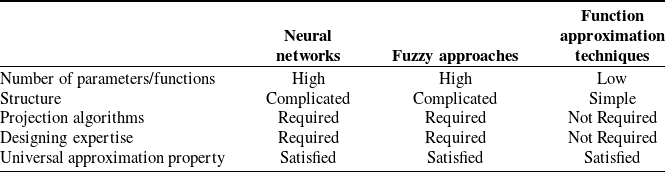
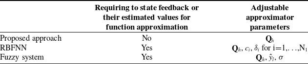
Function approximation technique is another efficient model-free approach utilized for designing observer-based control schemes. These approaches are able to estimate unmodulated dynamics and unmeasured system states based on powerful mathematical operators [Reference Izadbakhsh, Khorashadizadeh and Ghandali17–Reference Izadbakhsh, Zamani and Khorashadizadeh20]. In this article, an adaptive FAT-based observer–controller structure will be introduced for multiple robotic manipulators. The motivation of adopting FAT-based approaches for designing the structure is the significant advantages of these approaches compared to both model-based and model-free neuro-fuzzy methods, which make them good candidates for dealing with disturbances and uncertainties [Reference Izadbakhsh21]. These advantages are as follows: (1) In model-based control methods, change of parameters may affect the system performance significantly. Compared to these approaches, FAT-based methods are not dependent on system modeling. Therefore, the existence of unmodeled dynamics does not deteriorate their performance; (2) Designing systems based on fuzzy logic or neural networks requires sufficient expertise to determine the parameters of the estimator/controller. Lack of enough experience will turn the design process into time-consuming and tedious work because it is necessary to determine the parameters based on trial and error. In FAT-based approaches, on the other hand, because of the simple structure and the limited number of parameters, their values can be easily determined; (3) In neuro-fuzzy systems, to keep the parameters in a particular range, projection algorithms are usually needed, which raises the computational load of the controller further; (4) Neuro-fuzzy structures usually require different feedbacks from system states. For example, when uncertainty is a function of system states, the neuro-fuzzy approximator needs to receive those states as inputs, which raises the computational complexity of the system. FAT-based estimators, on the other hand, approximate functions as time series and are not dependent on system states. This results in the reduction of system computational load [Reference Chien and Huang22]. Table I compares the main properties of function approximation techniques, fuzzy approaches, and neural networks.
A comparison among neural networks, fuzzy approaches, and function approximation techniques.

In this article, the FAT is used to deal with unmodulated dynamics and disturbances so that the impact of these factors does not cause a decline in system performance. For this purpose, the Fourier series expansion is used to estimate of uncertainties and disturbances, and the coefficients of this series are updated by developing adaptive rules. Stability analysis is carried out thoroughly using the Lyapunov theorem to confirm the boundedness of all error signals. Finally, to evaluate the efficiency of the proposed adaptive FAT-based method, it is applied to two 3-DOF robotic arms carrying a payload. The novelty and merits of the presented method are as follows: (1) To the best of the authors’ knowledge, the present article is the first usage of Fourier series expansion in robust adaptive control of electrically driven cooperative multiple manipulators; (2) The introduced controller is regressor-free. So, the problems of the usual adaptive methods do not appear in the proposed controller; (3) One of the advantages of the developed strategy is that there is no need for the measurement of joint velocity, and joint position is the only measured state; (4) Moreover, in most of the previously developed robot controllers, the joint torque is used as the control signal, and actuator dynamics are neglected. However, as a more realistic presumption, in this work, actuator voltages are considered as the control signals.
The different sections of this study are as follows: Section 2 formulates the cooperating robotic system dynamics. Section 3 gives the proposed observer and controller design procedures. Stability analysis is also presented in this section. Section 4 illustrates the simulation results, and section 5 gives the most important concluding remarks. Throughout this article,
 $\lambda_{\textrm{min}}(\bullet)$
denotes the minimum eigenvalue of a bounded positive-definite matrix
 $(\bullet)$
, and
 $\lambda_{\textrm{max}}(\bullet)$
is the corresponding maximum eigenvalue. Suppose a vector
 ${\bf{y}} \in {{\mathfrak{R}} ^n}$
. Its norm is indicated as
 $\left\| {\bf{y}} \right\| = \sqrt {{{\bf{y}}^T}{\bf{y}}} $
, and the norm of the matrix
 ${\bf{{E}}}$
is calculated as
 $\left\| {{\bf{{E}}}(y)} \right\| = \sqrt {\bar \lambda ({\bf{{ E}}}{{(y)}^T}{\bf{{ E}}}(y))} $
.
2. Dynamic model of coordinated robotic systems
2.1. System overview
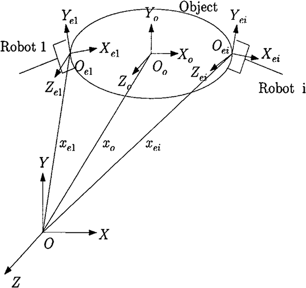
A typical object is considered to be handled by m actuated robotic arms, which have n-DOF, in the workspace. In order to model the system, separate coordinate frames are established as presented in Fig. 1. The end effector and object positions, as well as their orientations, are referred to in the base frame, denoted by
 $\textrm{OXYZ}$
. The coordinate frame of the object defined as
 ${\textrm{O}_{\textrm{o}}}{\textrm{X}_{\textrm{o}}}{\textrm{Y}_{\textrm{o}}}{\textrm{Z}_{\textrm{o}}}$
is placed at its center of mass (COM). For ith manipulator, the coordinate frame
 ${\textrm{O}_{\textrm{ei}}}{\textrm{X}_{\textrm{ei}}}{\textrm{Y}_{\textrm{ei}}}{\textrm{Z}_{\textrm{ei}}}$
is considered at its grasp point. Some assumptions are presumed to establish the dynamic model of the system as mentioned in refs. [Reference Jean and Fu23 and Reference Song and Cai24].
Coordinate frames of the cooperative system.

2.2. Actuated robot dynamic model
Consider the following well-known differential equations of motion, which describes the rotational behavior of n permanent magnet DC motors driving an n degree of freedom robot. These equations are [Reference Spong and Vidyasagar25]
 \begin{equation}{{\bf{J}}_{ai}}{\bf{r}}_i^{ - 1}{\ddot{\bf{q}}_i} + ({{\bf{b}}_{ai}} + {{\bf{k}}_{ai}}{{\bf{k}}_{bi}}{\bf{R}}_i^{ - 1}){\bf{r}}_i^{ - 1}{\dot{\bf{q}}_i} = {{\bf{k}}_{ai}}{\bf{R}}_i^{ - 1}{{\bf{v}}_i}(t) - {{\bf{r}}_i}{{\boldsymbol{\tau }}_{li}},\qquad {\textrm{i = 1,2,}}\ldots {\textrm{,m}}\end{equation}
Furthermore, the ith manipulator dynamic model in the joint space is formulated as [Reference Woon, Ge, Chen and Zhang26]
 \begin{equation}{{\bf{D}}_i}({{\bf{q}}_i}){\ddot{\bf{q}}_i} + {{\bf{C}}_i}({{\bf{q}}_i},{\dot{\bf{q}}_i}){\dot{\bf{q}}_i} + {{\bf{G}}_i}({{\bf{q}}_i}) = {{\boldsymbol{\tau }}_{li}} - {\bf{J}}_{ei}^T({{\bf{q}}_i}){{\bf{F}}_{ei}},\qquad {\textrm{i = 1,2,}}\ldots{\textrm{,m}}\end{equation}
where the parameters and dimensions are defined exactly similar to refs. [Reference Spong and Vidyasagar25 and Reference Woon, Ge, Chen and Zhang26]. Concise representation of m manipulators dynamics actuated by permanent magnet DC motors (1) is
 \begin{equation}\bar{\bf{D}}({\bf{q}}){\ddot{\bf{q}}} + \bar{\bf{C}}({\bf{q}},{\dot{\bf{q}}}){\dot{\bf{q}}} + {\bf{G}}({\bf{q}}) = {{\bf{r}}^{ - 1}}{{\bf{k}}_a}{{\bf{R}}^{ - 1}}{\bf{v}} - {\bf{J}}_e^T({\bf{q}}){{\bf{F}}_e}\end{equation}
where
 \begin{align}{\bf{q}} & = {\left[ {\begin{array}{c@{\quad}c@{\quad}c@{\quad}c}{{\bf{q}}_1^T} & {{\bf{q}}_2^T} & \ldots & {{\bf{q}}_m^T}\end{array}} \right]^T} \in {{\mathfrak{R}} ^{mn}}\nonumber\\[4pt]{\bf{v}} & = {\left[ {\begin{array}{c@{\quad}c@{\quad}c@{\quad}c}{{\bf{v}}_1^T} & {{\bf{v}}_2^T} & \ldots & {{\bf{v}}_m^T}\end{array}} \right]^T} \in {{\mathfrak{R}} ^{mn}}\nonumber\\[4pt]\bar{\bf{D}}({\bf{q}}) & = blockdiag\left[ {\begin{array}{c@{\quad}c@{\quad}c@{\quad}c}{{{\bf{D}}_1}({{\bf{q}}_1}) + {\bf{r}}_1^{ - 1}{{\bf{J}}_{a1}}{\bf{r}}_1^{ - 1}} & {{{\bf{D}}_2}({{\bf{q}}_2}) + {\bf{r}}_2^{ - 1}{{\bf{J}}_{a2}}{\bf{r}}_2^{ - 1}} & \ldots & {{{\bf{D}}_m}({{\bf{q}}_m}) + {\bf{r}}_m^{ - 1}{{\bf{J}}_{am}}{\bf{r}}_m^{ - 1}}\end{array}} \right] \in {{\mathfrak{R}} ^{mn \times mn}}\nonumber\\[4pt]\bar{\bf{C}}({\bf{q}},{\dot{\bf{q}}}) & = blockdiag\left[{{{\bf{C}}_1}({{\bf{q}}_1},{{\dot{\bf{q}}}_1}) + {\bf{r}}_1^{ - 1}({{\bf{b}}_{a1}} + {{\bf{k}}_{a1}}{{\bf{k}}_{b1}}{\bf{R}}_1^{ - 1}){\bf{r}}_1^{ - 1}} \ldots \right.\nonumber\\[4pt]& \qquad\qquad \left. {{{\bf{C}}_m}({{\bf{q}}_m},{{\dot{\bf{q}}}_m}) + {\bf{r}}_m^{ - 1}({{\bf{b}}_{am}} + {{\bf{k}}_{am}}{{\bf{k}}_{bm}}{\bf{R}}_m^{ - 1}){\bf{r}}_m^{ - 1}} \right] \in {{\mathfrak{R}} ^{mn \times mn}}\\[4pt]{\bf{G}}({\bf{q}}) & = {\left[ {\begin{array}{c@{\quad}c@{\quad}c@{\quad}c}{{{\bf{G}}_1}({{\bf{q}}_1})} & {{{\bf{G}}_2}({{\bf{q}}_2})} & \ldots & {{{\bf{G}}_m}({{\bf{q}}_m})}\end{array}} \right]^T} \in {{\mathfrak{R}} ^{mn}}\nonumber\\[4pt]{{\bf{r}}^{ - 1}}{{\bf{k}}_a}{{\bf{R}}^{ - 1}} & = blockdiag\left[ {\begin{array}{c@{\quad}c@{\quad}c@{\quad}c}{{\bf{r}}_1^{ - 1}{{\bf{k}}_{a1}}{\bf{R}}_1^{ - 1}} & {{\bf{r}}_2^{ - 1}{{\bf{k}}_{a2}}{\bf{R}}_2^{ - 1}} & \ldots & {{\bf{r}}_m^{ - 1}{{\bf{k}}_{am}}{\bf{R}}_m^{ - 1}}\end{array}} \right] \in {{\mathfrak{R}} ^{mn \times mn}}\nonumber\\[4pt]{{\bf{J}}_e}({\bf{q}}) & = blockdiag\left[ {\begin{array}{c@{\quad}c@{\quad}c@{\quad}c}{{\bf{J}}_{e1}^T({{\bf{q}}_1})} & {{\bf{J}}_{e2}^T({{\bf{q}}_2})} & \ldots & {{\bf{J}}_{em}^T({{\bf{q}}_m})}\end{array}} \right] \in {{\mathfrak{R}} ^{mn \times mn}}\nonumber\\[4pt]{{\bf{F}}_e} & = {\left[ {\begin{array}{c@{\quad}c@{\quad}c@{\quad}c}{{\bf{F}}_{e1}^T} & {{\bf{F}}_{e2}^T} & \ldots & {{\bf{F}}_{em}^T}\end{array}} \right]^T} \in {{\mathfrak{R}} ^{mn}}\nonumber\end{align}
2.3. Dynamic model of the object
The object motion is formulated as [Reference Jean and Fu23, Reference Yao and Tomizuka27],
 \begin{equation}{{\bf{D}}_o}({{\bf{x}}_o}){\ddot{\bf{x}}_o} + {{\bf{C}}_o}({{\bf{x}}_o},{\dot{\bf{x}}_o}){\dot{\bf{x}}_o} + {{\bf{G}}_o}({{\bf{x}}_o}) = {{\bf{F}}_o}\end{equation}
In this equation,
 ${{\bf{x}}_o} \in {{\mathfrak{R}} ^n}$
denotes the object frame (
 ${\textrm{O}_{\textrm{o}}}{\textrm{X}_{\textrm{o}}}{\textrm{Y}_{\textrm{o}}}{\textrm{Z}_{\textrm{o}}}$
) position vector, as well as its orientation vector, relative to the base frame (
 $\textrm{OXYZ}$
). The object inertial matrix, which is positive definite, and symmetric is represented by
 ${{\bf{D}}_o}({{\bf{x}}_o}) \in {{\mathfrak{R}} ^{n \times n}}$
. The centrifugal and Coriolis matrix is shown by
 ${{\bf{C}}_o}({{\bf{x}}_o},{\dot{\bf{x}}_o}) \in {{\mathfrak{R}} ^{n \times n}}$
.
 ${{\bf{G}}_o}({{\bf{x}}_o}) \in {{\mathfrak{R}} ^n}$
shows the gravitational vector, and the force exerted on the COM of the object is presented by
 ${{\bf{F}}_o} \in {{\mathfrak{R}} ^n}$
.
Consider
 ${{\bf{J}}_o}({{\bf{x}}_o}) \in {{\mathfrak{R}} ^{mn \times n}}$
to be defined as
 \begin{equation}{{\bf{J}}_o}({{\bf{x}}_o}) = {\left[ {\begin{array}{c@{\quad}c@{\quad}c@{\quad}c}{{\bf{J}}_{o1}^T({{\bf{x}}_o})} & {{\bf{J}}_{o2}^T({{\bf{x}}_o})} & \ldots & {{\bf{J}}_{om}^T({{\bf{x}}_o})}\end{array}} \right]^T}\end{equation}
where
 ${{\bf{J}}_{oi}}({{\bf{x}}_o}) \in {{\mathfrak{R}} ^{n \times n}}$
stands for the object frame (
 ${\textrm{O}_{\textrm{o}}}{\textrm{X}_{\textrm{o}}}{\textrm{Y}_{\textrm{o}}}{\textrm{Z}_{\textrm{o}}}$
) Jacobian matrix relative to the ith robot end-effector frame (
 ${\textrm{O}_{\textrm{ei}}}{\textrm{X}_{\textrm{ei}}}{\textrm{Y}_{\textrm{ei}}}{\textrm{Z}_{\textrm{ei}}}$
). Therefore,
 ${{\bf{F}}_o}$
is obtained
 \begin{equation}{{\bf{F}}_o} = {\bf{J}}_o^T({{\bf{x}}_o}){{\bf{F}}_e}\end{equation}
When the consequent force
 ${{\bf{F}}_o}$
is known, the end-effector force
 ${{\bf{F}}_e}$
, which fulfils (7), is decomposable into two orthogonal parts corresponding to the motion of the object and the internal force production. Eq. (8) represents this decomposition [Reference Jean and Fu23, Reference Song and Cai24].
 \begin{equation}{{\bf{F}}_e} = {({\bf{J}}_o^T({{\bf{x}}_o}))^ + }{{\bf{F}}_o} + {{\bf{F}}_I}\end{equation}
where
 ${({\bf{J}}_o^T({{\bf{x}}_o}))^ + } = {{\bf{J}}_o}({{\bf{x}}_o}){({\bf{J}}_o^T({{\bf{x}}_o}){{\bf{J}}_o}({{\bf{x}}_o}))^{ - 1}} \in {{\mathfrak{R}} ^{mn \times n}}$
represents the pseudo-inverse of
 ${\bf{J}}_o^T({{\bf{x}}_o})$
, and the internal force vector is represented by
 ${{\bf{F}}_I} \in {{\mathfrak{R}} ^{mn}}$
which is defined in the
 ${\bf{J}}_o^T({{\bf{x}}_o})$
null space, which means that it satisfies
 \begin{equation}{\bf{J}}_o^T({{\bf{x}}_o}){{\bf{F}}_I} = 0\end{equation}
Combining (5) and (8) results in
 \begin{equation}{{\bf{F}}_e} = {({\bf{J}}_o^T({{\bf{x}}_o}))^ + }\left( {{{\bf{D}}_o}({{\bf{x}}_o}){{\ddot{\bf{x}}}_o} + {{\bf{C}}_o}({{\bf{x}}_o},{{\dot{\bf{x}}}_o}){{\dot{\bf{x}}}_o} + {{\bf{G}}_o}({{\bf{x}}_o})} \right) + {{\bf{F}}_I}\end{equation}
2.4. Combined whole system dynamics
The total number of position variables introduced in (3) and (5) is equal to (m+1)n; n of which are independent. Equations (3) and (5) are not appropriate for analyzing system dynamics due to position variables dependence. So, the dynamic model (3) can be formulated using the object position
 ${{\bf{x}}_o}$
because of its independence. Let
 ${{\bf{x}}_{ei}} \in {{\mathfrak{R}} ^n}$
denote the position and orientation vector of the ith end effector. Then
 ${\dot{\bf{x}}_{ei}}$
is related to
 ${\dot{\bf{q}}_i}$
by the Jacobian matrix
 ${{\bf{J}}_{ei}}({{\bf{q}}_i})$
as
 \begin{equation}{\dot{\bf{x}}_{ei}} = {{\bf{J}}_{ei}}({{\bf{q}}_i}){\dot{\bf{q}}_i}\end{equation}
and the relationship between
 ${\dot{\bf{x}}_{ei}}$
and
 ${\dot{\bf{x}}_o}$
is given by
 \begin{equation}{\dot{\bf{x}}_{ei}} = {{\bf{J}}_{oi}}({{\bf{x}}_o}){\dot{\bf{x}}_o}\end{equation}
After combining (11) and (12), the assumption of working manipulators in a nonsingular region, and considering all the manipulators acting on the object at the same time, we have
 \begin{equation}{\dot{\bf{q}}} = {\bf{J}}_e^{ - 1}({\bf{q}}){{\bf{J}}_o}({{\bf{x}}_o}){\dot{\bf{x}}_o}\end{equation}
Applying (10), (13) and its time derivative into (3), premultiplying both sides of the obtained equation by
 ${\bf{J}}_o^T({{\bf{x}}_o}){\bf{J}}_e^{ - T}({\bf{q}})$
, and using the fact that
 ${\bf{J}}_o^T({{\bf{x}}_o}){{\bf{F}}_I} = 0$
, the dynamic model of the multiple manipulators system (3), coupled with the object dynamics (5), is then given by
 \begin{equation}{{\bf{M}}_c}({{\bf{x}}_o}){\ddot{\bf{x}}_o} + {{\bf{C}}_c}({{\bf{x}}_o},{\dot{\bf{x}}_o}){\dot{\bf{x}}_o} + {{\bf{G}}_c}({{\bf{x}}_o}) + {\boldsymbol{\delta }}({{\bf{x}}_o},{\bf{v}}) = {\bf{u}}\end{equation}
where
 \begin{align*}{{\bf{M}}_c}\left({{\bf{x}}_o}\right) & = {\bf{J}}_o^T\left({{\bf{x}}_o}\right){\bf{J}}_e^{ - T}\left({\bf{q}}\right)\bar{\bf{D}}\left({\bf{q}}\right){\bf{J}}_e^{ - 1}\left({\bf{q}}\right){{\bf{J}}_o}\left({{\bf{x}}_o}\right) + {{\bf{D}}_o}\left({{\bf{x}}_o}\right) \in {{\mathfrak{R}} ^{n \times n}}\\[3pt] {{\bf{C}}_c}\left({{\bf{x}}_o},{{\dot{\bf{x}}}_o}\right) & = {\bf{J}}_o^T\left({{\bf{x}}_o}\right){\bf{J}}_e^{ - T}\left({\bf{q}}\right)\left(\bar{\bf{D}}\left({\bf{q}}\right)\frac{d}{{dt}}\left({\bf{J}}_e^{ - 1}\left({\bf{q}}\right){{\bf{J}}_o}\left({{\bf{x}}_o}\right)\right) + \bar{\bf{C}}\left({\bf{q}},{\dot{\bf{q}}}\right){\bf{J}}_e^{ - 1}\left({\bf{q}}\right){{\bf{J}}_o}\left({{\bf{x}}_o}\right)\right)\\[3pt] & + {{\bf{C}}_o}\left({{\bf{x}}_o},{{\dot{\bf{x}}}_o}\right) \in {{\mathfrak{R}} ^{n \times n}}\\[3pt] {{\bf{G}}_c}\left({{\bf{x}}_o}\right) & = {\bf{J}}_o^T\left({{\bf{x}}_o}\right){\bf{J}}_e^{ - T}\left({\bf{q}}\right){\bf{G}}\left({\bf{q}}\right) + {{\bf{G}}_o}\left({{\bf{x}}_o}\right) \in {{\mathfrak{R}} ^n}\\[3pt] {\bf{u}} & = {\bf{J}}_o^T\left({{\bf{x}}_o}\right){\bf{J}}_e^{ - T}\left({\bf{q}}\right){\bf{v}} \in {{\mathfrak{R}} ^n}\\[3pt] {\boldsymbol{\delta }}\left({{\bf{x}}_o},{\bf{v}}\right) & = {\bf{J}}_o^T\left({{\bf{x}}_o}\right){\bf{J}}_e^{ - T}\left({\bf{q}}\right)\left({{\bf{I}}_{mn}} - {{\bf{r}}^{ - 1}}{{\bf{k}}_a}{{\bf{R}}^{ - 1}}\right){\bf{v}} \in {{\mathfrak{R}} ^n}\end{align*}
with
 ${{\bf{I}}_{mn}}$
denoting a block diagonal of m identity matrix with dimension n.
3. Controller–Observer robust scheme
3.1. Controller design
As can be seen form Eq. (14), the mathematical relation between the operational space pose (position and orientation) and control inputs, contains the time derivative, inverse as well as transpose transformation of the Jacobian matrix, that can burden the control system and reduce its performance. Thus, controller design for such highly nonlinear dynamics is generally complex and computationally difficult due to complexity or uncertainties in
 ${{\bf{M}}_c}({{\bf{x}}_o})$
,
 ${{\bf{C}}_c}({{\bf{x}}_o},{\dot{\bf{x}}_o})$
,
 ${{\bf{G}}_c}({{\bf{x}}_o})$
and
 ${\boldsymbol{\delta }}({{\bf{x}}_o},{\bf{v}})$
. This problem becomes hypersensitive by increasing the number of cooperative manipulators and related DOF. The control objective for the actuated robotic system is hence to drive the COM of the moving object to follow a desired trajectory defined in task space, in the presence of unknown disturbances and uncertainties in the manipulator dynamics without velocity measurement. Toward this end, a FAT-based adaptive control scheme is developed in this section using Function approximation Technique. Assume that Eq. (14) can be rewritten as follows
 \begin{equation}{\ddot{\bf{x}}_o} + {\bf{h}}(t) = {\bf{u}}\end{equation}
where
 \begin{equation}{\bf{h}}\left(t\right) = \left({{\bf{I}}_n} - {\bf{M}}_c^{ - 1}\left({{\bf{x}}_o}\right)\right){\bf{u}} + {\bf{M}}_c^{ - 1}\left({{\bf{x}}_o}\right)\left({{\bf{C}}_c}\left({{\bf{x}}_o},{\dot{\bf{x}}_o}\right){\dot{\bf{x}}_o} + {{\bf{G}}_c}\left({{\bf{x}}_o}\right) + {\boldsymbol{\delta }}\left({{\bf{x}}_o},{\bf{v}}\right)\right)\end{equation}
represents an n-dimensional vector of uncertainties with
 ${{\bf{I}}_n}$
denoting an
 $n \times n$
identity matrix. Before we go into the details of controller derivation, we present the two following assumptions.
Assumption 1. Suppose that the bounded nonlinear function
 ${\bf{h}}(t)$
is time varying and unknown. Also, suppose that its variation bound is not in hand. As a result, it is not possible to apply the traditional robust or adaptive control scheme [Reference Huang and Chen28].
Assumption 2. The desired trajectory of the object,
 ${{\bf{x}}_{od}} \in {{\mathfrak{R}} ^n}$
, is assumed to be bounded and uniformly continuous, and has bounded and uniformly continuous derivatives up to a necessary order.
Consider the following definitions:
 \begin{equation}{\dot{\bf{x}}_r} = {\dot{\bf{x}}_{od}} - {\boldsymbol{\Lambda }}({\hat{\bf{x}}_o} - {{\bf{x}}_{od}}) = {\dot{\bf{x}}_{od}} + {\boldsymbol{\Lambda }}({\tilde{\bf{x}}_o} - {{\bf{e}}_o})\end{equation}
 \begin{equation}{\bf{s}} = {\dot{\bf{x}}_o} - {\dot{\bf{x}}_r} = {\dot{\bf{e}}_o} + {\boldsymbol{\Lambda }}({{\bf{e}}_o} - {\tilde{\bf{x}}_o})\end{equation}
 \begin{equation}{\dot{\bf{x}}_\Xi } = {\dot{\hat{\bf{x}}}_o} - {\boldsymbol{\Lambda }}{\tilde{\bf{x}}_o}\end{equation}
 \begin{equation}{\bf{r}} = {\dot{\bf{x}}_o} - {\dot{\bf{x}}_\Xi } = {\dot{\tilde{\bf{x}}}_o} + {\boldsymbol{\Lambda }}{\tilde{\bf{x}}_o}\end{equation}
where
 ${\tilde{\bf{x}}_o} = {{\bf{x}}_o} - {\hat{\bf{x}}_o}$
and
 ${{\bf{e}}_o} = {{\bf{x}}_o} - {{\bf{x}}_{od}}$
represent the observation and tracking errors for the object position/orientation, respectively. The proposed controller is given by
 \begin{equation}{\bf{u}} = {\ddot{\bf{x}}_r} + \hat{\bf{h}}(t) - {{\unicode[Kappa]{x1D6CB}}_r}({\dot{\bf{x}}_\Xi } - {{\dot{\bf{x}}}_r})\end{equation}
where
 $\hat{\bf{h}}(t)$
is estimation of
 ${\bf{h}}(t)$
; and
 ${{\unicode[Kappa]{x1D6CB}}_r} \in {{\mathfrak{R}} ^{n \times n}}$
is a diagonal positive definite constant matrix. Since
 ${{\dot{\bf{x}}}_\Xi } - {{\dot{\bf{x}}}_r} = {\bf{s}} - {\bf{r}}$
, (21) can be written as
 \begin{equation}{\bf{u}} = {\ddot{\bf{x}}_r} + \hat{\bf{h}}(t) - {{\unicode[Kappa]{x1D6CB}}_r}({\bf{s}} - {\bf{r}})\end{equation}
Substituting (22) into (15) and using (18) gives
 \begin{equation}\dot{\bf{s}} = \hat{\bf{h}}(t) - {\bf{h}}(t) - {{\unicode[Kappa]{x1D6CB}}_r}{\bf{s}} + {{\unicode[Kappa]{x1D6CB}}_r}{\bf{r}}\end{equation}
If an adaptation rule is designed based on the stability analysis so that
 $\hat{\bf{h}}(t) \to {\bf{h}}(t)$
, then boundedness of
 ${\bf{s}}$
will be guaranteed from (23) if
 ${\bf{r}}$
be bounded. With this in mind, the Fourier series (FS) expansion is used to represent
 ${\bf{h}}(t)$
as linear combinations of basis functions as
 \begin{equation}{\bf{h}}(t) = {\bf{W}}_{\bf{h}}^T{{\bf{Z}}_{\bf{h}}} + {{\unicode[varepsilon]{x1D6C6}}_{\bf{h}}}\end{equation}
where
 ${{\bf{W}}_{\bf{h}}} \in {{\mathfrak{R}} ^{n{\beta _{\bf{h}}} \times n}}$
is the Fourier series coefficient,
 ${\beta _{\bf{h}}}$
is the number of basis function,
 ${{\bf{Z}}_{\bf{h}}} \in {{\mathfrak{R}} ^{n{\beta _{\bf{h}}}}}$
is vector of sinusoidal functions, and
 ${{\unicode[varepsilon]{x1D6C6}}_{\bf{h}}}$
is the truncation error vector of
 ${\bf{h}}(t)$
. It is obvious that based on the Fourier series, the corresponding estimates can be also represented by
 \begin{equation}\hat{\bf{h}}(t) = \hat{\bf{W}}_{\bf{h}}^T{{\bf{Z}}_{\bf{h}}}\end{equation}
where
 ${\hat{\bf{W}}_{\bf{h}}} \in {{\mathfrak{R}} ^{n{\beta _{\bf{h}}} \times n}}$
is the estimation of
 ${{\bf{W}}_{\bf{h}}}$
. Now, substitution of (24) and (25) into (23) results in:
 \begin{equation}{\dot{\bf{s}}} = - {{\unicode[Kappa]{x1D6CB}}_r}{\bf{s}} + {{\unicode[Kappa]{x1D6CB}}_r}{\bf{r}} - \tilde{\bf{W}}_{\bf{h}}^T{{\bf{Z}}_{\bf{h}}} + {{\unicode[varepsilon]{x1D6C6}}_{\bf{h}}}\end{equation}
in which
 ${\tilde{\bf{W}}_{\bf{h}}} = {{\bf{W}}_{\bf{h}}} - {\hat{\bf{W}}_{\bf{h}}}$
is the error vector related to the FS coefficients.
Remark 1. The considerable point is that the voltage signal
 ${\bf{v}}$
is the actual control input that should be applied to the robotic system. Toward this end, the motion control law is introduced as follows
 \begin{equation}{\bf{v}} = {\bf{J}}_e^T({\bf{q}}){({\bf{J}}_o^T({{\bf{x}}_o}))^ + }{\bf{u}} + {\bf{J}}_e^T({\bf{q}}){{\bf{F}}_{Ic}}\end{equation}
where
 ${{\bf{F}}_{Ic}} \in {{\mathfrak{R}} ^{mn}}$
is the internal force control term defined as
 \begin{equation}{{\bf{F}}_{Ic}} = {{\bf{F}}_{Id}} + {{\bf{K}}_I}({{\bf{F}}_{Id}} - {{\bf{F}}_I})\end{equation}
with
 ${{\bf{K}}_I} \in {{\mathfrak{R}} ^{mn \times mn}}$
denoting a positive diagonal gain matrix. Note that since
 ${{\bf{F}}_{Id}}$
is in the null space of
 ${\bf{J}}_o^T({{\bf{x}}_o})$
, so is
 ${{\bf{F}}_{Ic}}$
.
3.2. Observer design
The proposed linear observer is [Reference Arteaga and Kelly29]
 \begin{equation}{\dot{\hat{\bf{x}}}_o} = {\dot{\hat{\bf{x}}}_\Xi } + {\boldsymbol{\Lambda }}{\tilde{\bf{x}}_o} + k{\tilde{\bf{x}}_o}\end{equation}
 \begin{equation}{\ddot{\hat{\bf{x}}}_\Xi } = {\ddot{\bf{x}}_r} + k{\boldsymbol{\Lambda }}{\tilde{\bf{x}}_o}\end{equation}
where
 $k$
is a positive real constant. The initial condition for the observer may be chosen as
 ${\dot{\hat{\bf{x}}}_\Xi }(0) = - ({\boldsymbol{\Lambda }}{\tilde{\bf{x}}_o}(0) + k{\tilde{\bf{x}}_o}(0))$
and
 ${\hat{\bf{x}}_o}(0) = {{\bf{x}}_o}(0)$
to have
 ${\dot{\hat{\bf{x}}}_o}(0) = 0$
and
 ${\tilde{\bf{x}}_o}(0) = 0$
(although this is not necessary for stability purposes). Since form (29), one has
 ${\ddot{\hat{\bf{x}}}_o} = {\ddot{\hat{\bf{x}}}_\Xi } + {\boldsymbol{\Lambda }}{\dot{\tilde{\bf{x}}}_o} + k{\dot{\tilde{\bf{x}}}_o}$
, it is straightforward to show that (29) and (30) are equivalent to
 ${\dot{\bf{r}}} = \dot{\bf{s}} - k{\bf{r}}$
.Utilizing Eq. (26), one gets after some manipulation
 \begin{equation}\dot{\bf{r}} = - {{\unicode[Kappa]{x1D6CB}}_r}{\bf{s}} - {\boldsymbol{\Gamma} \textbf{r}} - \tilde{\bf{W}}_{\bf{h}}^T{{\bf{Z}}_{\bf{h}}} + {{\unicode[varepsilon]{x1D6C6}}_{\bf{h}}}\end{equation}
where
 ${\boldsymbol{\Gamma }} = k{{\bf{I}}_n} - {{\unicode[Kappa]{x1D6CB}}_r}$
.
3.3. Stability analysis
Consider the following positive-definite function
 \begin{equation}V\left({\bf{r}},{\bf{s}},{\tilde{\bf{W}}_{\bf{h}}}\right) = \frac{1}{2}\left[ {\begin{array}{c@{\quad}c}{{{\bf{r}}^T}} & {{{\bf{s}}^T}}\end{array}} \right]{\bf{P}}\left[ {\begin{array}{c}{\bf{r}}\\[4pt]{\bf{s}}\end{array}} \right] + \frac{1}{2}Tr\left(\tilde{\bf{W}}_{\bf{h}}^T{{\bf{Q}}_{\bf{h}}}{\tilde{\bf{W}}_{\bf{h}}}\right)\end{equation}
where
 ${\bf{P}} = diag({{\bf{I}}_n},{{\bf{I}}_n}) \in {{\mathfrak{R}} ^{2n \times 2n}}$
,
 $ Tr(\bullet)$
is the trace operator and
 ${{\bf{Q}}_{\bf{h}}} \in {{\mathfrak{R}} ^{n{\beta _{\bf{h}}} \times n{\beta _{\bf{h}}}}}$
is a positive definite diagonal adaption gain matrix. For Eq. (32), we have
 \begin{equation}V\left({\bf{r}},{\bf{s}},{\tilde{\bf{W}}_{\bf{h}}}\right) \le \frac{1}{2}{\lambda _{\max }}({\bf{P}}){\left\| {\left[ {\begin{array}{c}{\bf{r}}\\[3pt]{\bf{s}}\end{array}} \right]} \right\|^2} + \frac{1}{2}{\lambda _{\max }}({{\bf{Q}}_{\bf{h}}})Tr\left(\tilde{\bf{W}}_{\bf{h}}^T{\tilde{\bf{W}}_{\bf{h}}}\right)\end{equation}
and
 \begin{equation}V\left({\bf{r}},{\bf{s}},{\tilde{\bf{W}}_{\bf{h}}}\right) \ge \frac{1}{2}{\lambda _{\min }}({\bf{P}}){\left\| {\left[ {\begin{array}{c}{\bf{r}}\\[3pt]{\bf{s}}\end{array}} \right]} \right\|^2} + \frac{1}{2}{\lambda _{\min }}({{\bf{Q}}_{\bf{h}}})Tr\left(\tilde{\bf{W}}_{\bf{h}}^T{\tilde{\bf{W}}_{\bf{h}}}\right)\end{equation}
Differentiating (32) with respect to time and using (26) and (31) results in
 \begin{align} \dot V\left({\bf{r}},{\bf{s}},{{\tilde{\bf{W}}}_{\bf{h}}}\right) & = - \left[ {\begin{array}{c@{\quad}c}{{{\bf{r}}^T}} & {{{\bf{s}}^T}}\end{array}} \right]{\unicode[varphi]{x1D6D7}}\left[ {\begin{array}{c}{\bf{r}}\\[4pt]{\bf{s}}\end{array}} \right] + \left[ {\begin{array}{c@{\quad}c}{{{\bf{r}}^T}} & {{{\bf{s}}^T}}\end{array}} \right]{\bf{B}}{{\unicode[varepsilon]{x1D6C6}}_{\bf{h}}} - Tr\left(\tilde{\bf{W}}_{\bf{h}}^T\left({{\bf{Q}}_{\bf{h}}}{{\dot{\hat{\bf{W}}}}_{\bf{h}}} + {{\bf{Z}}_{\bf{h}}}\left({{\bf{r}}^T} + {{\bf{s}}^T}\right)\right)\right)\end{align}
where
 ${{\bf{B}}^T} = \left[ {\begin{array}{c@{\quad}c}{{{\bf{I}}_n}} & {{{\bf{I}}_n}}\end{array}} \right] \in {{\mathfrak{R}} ^{n \times 2n}}$
and
 ${\unicode[varphi]{x1D6D7}} = \left[ {\begin{array}{c@{\quad}c}{\boldsymbol{\Gamma }} & {{{\bf{0}}_n}}\\{{{\bf{0}}_n}} & {{{\unicode[Kappa]{x1D6CB}}_r}}\end{array}} \right] \in {{\mathfrak{R}} ^{2n \times 2n}}$
is a positive-definite matrix with
 ${{\bf{0}}_n}$
denoting an
 $n \times n$
zero matrix. Proposing the adaptive rule as
 \begin{equation}{\dot{\hat{\bf{W}}}_{\bf{h}}} = - {\bf{Q}}_{\bf{h}}^{ - 1}\left({{\bf{Z}}_{\bf{h}}}\left({{\bf{r}}^T} + {{\bf{s}}^T}\right) + {\sigma _{\bf{h}}}{\hat{\bf{W}}_{\bf{h}}}\right)\end{equation}
and replacing in (35) yields
 \begin{equation}\dot V({\bf{r}},{\bf{s}},{\tilde{\bf{W}}_{\bf{h}}}) = - \left[ {\begin{array}{c@{\quad}c}{{{\bf{r}}^T}} & {{{\bf{s}}^T}}\end{array}} \right]{\unicode[varphi]{x1D6D7}}\left[ {\begin{array}{c}{\bf{r}}\\[4pt]{\bf{s}}\end{array}} \right] + \left[ {\begin{array}{c@{\quad}c}{{{\bf{r}}^T}} & {{{\bf{s}}^T}}\end{array}} \right]{\bf{B}}{{\unicode[varepsilon]{x1D6C6}}_{\bf{h}}} + {\sigma _{\bf{h}}}Tr\left(\tilde{\bf{W}}_{\bf{h}}^T{\hat{\bf{W}}_{\bf{h}}}\right)\end{equation}
Result 1. Consider the situation in which the required number of sinusoidal functions for the robotic system is selected and the truncation error is negligible. Then, we can exclude the
 $\sigma $
-modification terms in (36). As a result, (37) can be simplified as
 \begin{equation}\dot V\left({\bf{r}},{\bf{s}},{\tilde{\bf{W}}_{\bf{h}}}\right) \le - {\lambda _{\min }}({\unicode[varphi]{x1D6D7}}){\left\| {\left[ {\begin{array}{c}{\bf{r}}\\{\bf{s}}\end{array}} \right]} \right\|^2}\end{equation}
and using the Barbalat’s Lemma, the asymptotic convergence of
 ${\bf{r}}$
and
 ${\bf{s}}$
can be concluded.
Result 2. Assume that the truncation error cannot be ignored. It is easy to prove the following inequalities hold
 \begin{equation} - \left[ {\begin{array}{c@{\quad}c}{{{\bf{r}}^T}} & {{{\bf{s}}^T}}\end{array}} \right]{\unicode[varphi]{x1D6D7}}\left[ {\begin{array}{c}{\bf{r}}\\[4pt]{\bf{s}}\end{array}} \right] + \left[ {\begin{array}{c@{\quad}c}{{{\bf{r}}^T}} & {{{\bf{s}}^T}}\end{array}} \right]{\bf{B}}{{\unicode[varepsilon]{x1D6C6}}_{\bf{h}}} \le - \frac{1}{2}{\lambda _{\min }}({\unicode[varphi]{x1D6D7}}){\left\| {\left[ {\begin{array}{c}{\bf{r}}\\[4pt]{\bf{s}}\end{array}} \right]} \right\|^2} + \frac{{{{\bar \sigma }^2}({\bf{B}})}}{{2{\lambda _{\min }}({\unicode[varphi]{x1D6D7}})}}{\left\| {{{\unicode[varepsilon]{x1D6C6}}_{\bf{h}}}} \right\|^2}\end{equation}
 \begin{equation}2Tr(\tilde{\bf{W}}_{\bf{h}}^T{\hat{\bf{W}}_{\bf{h}}}) \le Tr\left({\bf{W}}_{\bf{h}}^T{{\bf{W}}_{\bf{h}}}\right) - Tr\left(\tilde{\bf{W}}_{\bf{h}}^T{\tilde{\bf{W}}_{\bf{h}}}\right)\end{equation}
where indicates the Euclidian norm and
 $\bar \sigma ({\bf{B}})$
represents the maximum singular value of
 ${\bf{B}}$
. Thus, we have
 \begin{equation}\dot V\left({\bf{r}},{\bf{s}},{{\tilde{\bf{W}}}_{\bf{h}}}\right) \le - \frac{1}{2}{\lambda _{\min }}({\unicode[varphi]{x1D6D7}}){\left\| {\left[ {\begin{array}{c}{\bf{r}}\\[4pt]{\bf{s}}\end{array}} \right]} \right\|^2} - \frac{{{\sigma _{\bf{h}}}}}{2}Tr\left(\tilde{\bf{W}}_{\bf{h}}^T{{\tilde{\bf{W}}}_{\bf{h}}}\right) + \frac{{{{\bar \sigma }^2}({\bf{B}})}}{{2{\lambda _{\min }}({\unicode[varphi]{x1D6D7}})}}{\left\| {{{\unicode[varepsilon]{x1D6C6}}_{\bf{h}}}} \right\|^2} + \frac{{{\sigma _{\bf{h}}}}}{2}Tr\left({\bf{W}}_{\bf{h}}^T{{\bf{W}}_{\bf{h}}}\right)\end{equation}
Utilizing (33), we relate (41) to
 $V$
in the form of
 \begin{align}\dot V\left({\bf{r}},{\bf{s}},{{\tilde{\bf{W}}}_{\bf{h}}}\right) \le - \mu V + \frac{1}{2}(\mu {\lambda _{\max }}({\bf{P}}) - {\lambda _{\min }}({\unicode[varphi]{x1D6D7}})){\left\| {\left[ {\begin{array}{c}{\bf{r}}\\[4pt]{\bf{s}}\end{array}} \right]} \right\|^2} + \dfrac{{{{\bar \sigma }^2}({\bf{B}})}}{{2{\lambda _{\min }}({\unicode[varphi]{x1D6D7}})}}{\left\| {{{\unicode[varepsilon]{x1D6C6}}_{\bf{h}}}} \right\|^2}\nonumber\\[10pt] + \dfrac{1}{2}(\mu {\lambda _{\max }}({{\bf{Q}}_{\bf{h}}}) - {\sigma _{\bf{h}}})Tr(\tilde{\bf{W}}_{\bf{h}}^T{{\tilde{\bf{W}}}_{\bf{h}}}) + \frac{{{\sigma _{\bf{h}}}}}{2}Tr\left({\bf{W}}_{\bf{h}}^T{{\bf{W}}_{\bf{h}}}\right)\end{align}
By selecting
 \begin{equation}\mu \le \min \left\{ {\frac{{{\lambda _{\min }}({\unicode[varphi]{x1D6D7}})}}{{{\lambda _{\max }}({\bf{P}})}},\frac{{{\sigma _{\bf{h}}}}}{{{\lambda _{\max }}({{\bf{Q}}_{\bf{h}}})}}} \right\}\end{equation}
Equation (42) can be further derived as
 \begin{equation}\dot V\left({\bf{r}},{\bf{s}},{\tilde{\bf{W}}_{\bf{h}}}\right) \le - \mu V + \frac{{{{\bar \sigma }^2}({\bf{B}})}}{{2{\lambda _{\min }}({\unicode[varphi]{x1D6D7}})}}{\left\| {{{\unicode[varepsilon]{x1D6C6}}_{\bf{h}}}} \right\|^2} + \frac{{{\sigma _{\bf{h}}}}}{2}Tr\left({\bf{W}}_{\bf{h}}^T{{\bf{W}}_{\bf{h}}}\right)\end{equation}
As a result
 $\dot V < 0$
, whenever
 \begin{equation}V > \frac{{{{\bar \sigma }^2}({\bf{B}})}}{{2\mu {\lambda _{\min }}({\unicode[varphi]{x1D6D7}})}}\mathop {\sup }\limits_{{t_0} < \varsigma } {\left\| {{{\unicode[varepsilon]{x1D6C6}}_{\bf{h}}}(\varsigma )} \right\|^2} + \frac{{{\sigma _{\bf{h}}}}}{{2\mu }}Tr\left({\bf{W}}_{\bf{h}}^T{{\bf{W}}_{\bf{h}}}\right)\end{equation}
Hence, we have proved that
 ${\bf{r}}$
,
 ${\bf{s}}$
, and
 ${\tilde{\bf{W}}_{\bf{h}}}$
are uniformly ultimately bounded. According to (20), we have
 ${\dot{\tilde{\bf{x}}}_o} + {\boldsymbol{\Lambda }}{\tilde{\bf{x}}_o} = {\bf{r}}$
that is a first-order stable linear filter with bounded input. As a result, both
 ${\tilde{\bf{x}}_o}$
and
 ${\dot{\tilde{\bf{x}}}_o}$
are bounded. From (18) we have
 ${\dot{\bf{e}}_o} + {\boldsymbol{\Lambda }}{{\bf{e}}_o} = {\bf{s}} + {\boldsymbol{\Lambda }}{\tilde{\bf{x}}_o}$
which guarantees boundedness of
 ${{\bf{e}}_o}$
and
 ${\dot{\bf{e}}_o}$
. It is because of the fact that the output of a stable linear filter, whose inputs are bounded, must also be bounded. The boundedness of the internal force errors can be also seen from the following equation derived from (14), (18), (22), and (27) as
 \begin{equation}({{\bf{F}}_{Id}} - {{\bf{F}}_I}) = {({{\bf{I}}_n} + {{\bf{K}}_I})^{ - 1}}\left\{ {{{({\bf{J}}_o^T({{\bf{x}}_o}))}^ + }({{\bf{M}}_c}({{\bf{x}}_o}){{\ddot{\bf{x}}}_o} + {{\bf{C}}_c}({{\bf{x}}_o},{{{\dot{\bf{x}}}}_o}){{{\dot{\bf{x}}}}_o} + } {{{\bf{G}}_c}({{\bf{x}}_o}) + {\boldsymbol{\delta }}({{\bf{x}}_o},{\bf{v}}) - {\bf{u}})} \right\}\end{equation}
It is clear that the force error is bounded and inversely proportional to the gain matrix
 $({{\bf{I}}_n} + {{\bf{K}}_I})$
. It can be reduced to an arbitrarily small value with sufficiently large gain
 ${{\bf{K}}_I}$
.
3.4. Performance assessment
Until now, we have demonstrated the boundedness of the closed-loop system. It should be mentioned that in practical implementations, the transient performance is also of great importance. Solving (44) yields
 \begin{equation}V(t) \le V({t_0}){e^{ - \mu (t - {t_0})}} + \frac{{{{\bar \sigma }^2}({\bf{B}})}}{{2\mu {\lambda _{\min }}({\unicode[varphi]{x1D6D7}})}}\mathop {\sup }\limits_{{t_0} < \varsigma < t} {\left\| {{{\unicode[varepsilon]{x1D6C6}}_{\bf{h}}}(\varsigma )} \right\|^2} + \frac{{{\sigma _{\bf{h}}}}}{{2\mu }}Tr\left({\bf{W}}_{\bf{h}}^T{{\bf{W}}_{\bf{h}}}\right)\end{equation}
According to the lower bound of Lyapunov function (34), we have
 \begin{equation}\left\| {\left[ {\begin{array}{c}{\bf{r}}\\[4pt]{\bf{s}}\end{array}} \right]} \right\| \le \sqrt {\frac{{2V}}{{{\lambda _{\min }}({\bf{P}})}}} \end{equation}
It enables one to define
 \begin{equation}\left\| {\left[ {\begin{array}{c}{\bf{r}}\\[4pt]{\bf{s}}\end{array}} \right]} \right\| \le \sqrt {\frac{{2V({t_0})}}{{{\lambda _{\min }}({\bf{P}})}}} {e^{ - 0.5\mu (t - {t_0})}} + \frac{{\bar \sigma ({\bf{B}})}}{{\sqrt {\mu {\lambda _{\min }}({\bf{P}}){\lambda _{\min }}({\unicode[varphi]{x1D6D7}})} }}\mathop {\sup }\limits_{{t_0} < \varsigma < t} \left\| {{{\unicode[varepsilon]{x1D6C6}}_{\bf{h}}}(\varsigma )} \right\| + \sqrt {\frac{{{\sigma _{\bf{h}}}}}{{\mu {\lambda _{\min }}({\bf{P}})}}Tr({\bf{W}}_{\bf{h}}^T{{\bf{W}}_{\bf{h}}})} \end{equation}
that means the tracking error is bounded by a weighted exponential function plus a constant. This also implies that by adjusting the controller parameters, we may improve the tracking error convergence rate. As a consequence,
 \begin{equation}\mathop {\lim }\limits_{t \to \infty } \left\| {\left[ {\begin{array}{c@{\quad}c@{\quad}c@{\quad}c}{\bf{r}}\\{\bf{s}}\end{array}} \right]} \right\| \le \frac{{\bar \sigma ({\bf{B}})}}{{\sqrt {\mu {\lambda _{\min }}({\bf{P}}){\lambda _{\min }}({\unicode[varphi]{x1D6D7}})} }}\mathop {\sup }\limits_{{t_0} < \varsigma < t} \left\| {{{\unicode[varepsilon]{x1D6C6}}_{\bf{h}}}(\varsigma )} \right\| + \sqrt {\frac{{{\sigma _{\bf{h}}}}}{{\mu {\lambda _{\min }}({\bf{P}})}}Tr({\bf{W}}_{\bf{h}}^T{{\bf{W}}_{\bf{h}}})}\end{equation}
This completes the transient performance analysis.
4. Numerical evaluation
4.1. The test bed system details
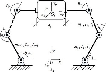
To apply the designed controller, a cooperative robotic system comprised of two 3-DOF manipulators handling a rigid object is considered as Fig. 2. Detailed information of system modeling (i.e., the manipulators Jacobian, gravity terms, Coriolis and centripetal matrix, and the inertia matrix) is given in ref. [Reference Uchiyama and Dauchez30]. The two manipulators are represented by the indices i = 1,2 throughout the simulation. Suppose that the reference frame is located in the middle of two robots and at the same distance from them. The numerical values of robot parameters are considered as
 ${\textrm{l}_{1,1}} = {\textrm{l}_{2,1}} = 2\,\textrm{m}$
,
 ${\textrm{l}_{1,2}} = {l_{2,2}} = 1.5\,\textrm{m}$
, and
 ${\textrm{l}_{1,3}} = {\textrm{l}_{2,3}} = 0.5\,\textrm{m}$
showing each link length.
 ${\textrm{m}_{1,1}} = {\textrm{m}_{2,1}} = 1.5\,\textrm{kg}$
,
 ${\textrm{m}_{1,2}} = {\textrm{m}_{2,2}} = 1\,\textrm{kg}$
, and
 ${\textrm{m}_{1,3}} = {\textrm{m}_{2,3}} = 0.5\,\textrm{kg}$
denote the link masses.
 ${\textrm{I}_{1,1}} = {\textrm{I}_{2,1}} = 0.7\,\textrm{kg}{\textrm{m}^2}$
,
 ${\textrm{I}_{1,2}} = {\textrm{I}_{2,2}} = 0.5\,\textrm{hg}{\textrm{m}^2}$
, and
 ${\textrm{I}_{1,3}} = {\textrm{I}_{2,3}} = 0.3\,\textrm{kg}{\textrm{m}^2}$
are the links moments of inertia [Reference Baigzadehnoe, Rahmani, Khosravi and Rezaie31]. The exact values of motor model parameters are set to
 ${{\bf{R}}_1} = {{\bf{R}}_2} = diag(2.1,2.1,2.1)[\Omega ]$
,
 ${{\bf{J}}_{a1}} = {{\bf{J}}_{a2}} = diag(2 \times {10^{ - 4}},2 \times {10^{ - 4}},2 \times {10^{ - 4}})[kg.{m^2}]$
,
 ${{\bf{r}}_1} = {{\bf{r}}_2} = diag({10^{ - 2}},{10^{ - 2}},{10^{ - 2}})$
,
 ${{\bf{k}}_{a1}} = {{\bf{k}}_{a2}} = {{\bf{k}}_{b1}} = {{\bf{k}}_{b2}} = diag(0.189,0.219,0.202)[N.m/A]$
and
 ${{\bf{b}}_{a1}} = {{\bf{b}}_{a2}} = diag(1.48,0.817,1.38) \times {10^{ - 3}}[N.m.s/rad]$
. The object was dynamically modeled as (5)–(7) where
 \begin{equation}{{\bf{D}}_o}({{\bf{x}}_o}) = \left[ {\begin{array}{c@{\quad}c@{\quad}c}{{m_o}} & 0 & 0\\[4pt]0 & {{m_o}} & 0\\[4pt]0 & 0 & {{I_o}}\end{array}} \right],{{\bf{G}}_o}({{\bf{x}}_o}) = \left[ {\begin{array}{c}0\\[4pt]{{m_o}g}\\[4pt]0\end{array}} \right]\end{equation}
Two 3-DOF cooperative manipulators [Reference Liu, Chen, Zhang and Chen33].

where the inertia of the object is represented by
 ${I_o}$
, and its mass is
 ${m_o}$
. The grasp matrix is given in the form of (6), where
 \begin{equation}{{\bf{J}}_{o1}}({{\bf{x}}_o}) = \left[ {\begin{array}{c@{\quad}c@{\quad}c}1 & 0 & {{l_{1l}}\sin ({x_{o3}})}\\[4pt]0 & 1 & { - {l_{1l}}\cos ({x_{o3}})}\\[4pt]0 & 0 & 1\end{array}} \right],{{\bf{J}}_{o2}}({{\bf{x}}_o}) = \left[ {\begin{array}{c@{\quad}c@{\quad}c}1 & 0 & { - {l_{2l}}\sin ({x_{o3}})}\\[4pt]0 & 1 & {{l_{2l}}\cos ({x_{o3}})}\\[4pt]0 & 0 & 1\end{array}} \right]\end{equation}
In this equation, the distance from the object COM and the ith end effector is denoted by
 ${l_{il}}$
, which is twice the object length.
 ${m_o}$
and
 ${I_o}$
are set to 0.2 kg and 0.1 kgm2, respectively. It is assumed that no information from the dynamics
 ${{\bf{M}}_{\textrm{c}}}({{\bf{x}}_{\textrm{o}}})$
,
 ${{\bf{C}}_{\textrm{c}}}({{\bf{x}}_{\textrm{o}}},{{\dot{\bf{x}}}_{\textrm{o}}})$
, and
 ${{\bf{G}}_{\textrm{c}}}({{\bf{x}}_{\textrm{o}}})$
is available. We suppose that an external disturbance is given by
 \begin{equation}{{\boldsymbol{\tau }}_{d,i}}(t) = \left[ {\begin{array}{c}{0.4\cos (2t)}\\[5pt]{0.1\sin (t) + \cos (2t)}\\[5pt]{0.2\sin (t)}\end{array}} \right],{\textrm{i = 1,2}}\end{equation}
which is added to each robot manipulator from the input channel. The numerical values of the controller–observer structure are
 ${\boldsymbol{\Lambda }} = diag{(20)_{3 \times 3}}$
,
 ${{\unicode[Kappa]{x1D6CB}}_r} = diag{(5)_{3 \times 3}}$
,
 $k = 10$
and
 ${{\bf{K}}_I} = diag{(100)_{6 \times 6}}$
. To approximate the lumped uncertainty
 ${\bf{h}}(t)$
, the first three terms of the Fourier series are chosen. So,
 ${\hat{\bf{W}}_{\bf{h}}} \in {{\mathfrak{R}} ^{9 \times 3}}$
. The adaptive parameters are initiated at zero. The convergence rate matrix is chosen as
 ${{\bf{Q}}_{\bf{h}}} = {10^{ - 4}} \times {{\bf{I}}_9}$
, where
 ${{\bf{I}}_9}$
represents the 9 × 9 identity matrix. At this point, assume that the estimation error is very small and therefore negligible, that is,
 ${\sigma _{\bf{h}}} = 0$
.
To investigate the efficiency of the proposed FAT-based approximator, its performance is compared with other estimators. For this purpose, the RBFNN and fuzzy system, as two state-of-art approximators, are integrated into the presented controller to estimate the external disturbances and the uncertainties. These methods are described in the following subsections.
4.2. First compared method: The RBFNN uncertainty approximator
To compare the results of the proposed technique and the RBFNN uncertainty approximator, both methods are integrated into the designed controller. RBFNN is used to estimate the uncertainties and external disturbances. The output of RBFNN is computed by a linear combination of hidden layer outputs of the neural network. Assume that the RBFNN inputs are the elements of the vector
 $\varpi (t) = {\left[ {\begin{array}{c@{\quad}c}{\hat{\bf{x}}_o^T(t)} & {{\dot{\hat{\bf{x}}}}_o^T(t)}\end{array}} \right]^T}$
. Consequently,
 \begin{equation}{{\bf{Z}}_h} = {\left[ {\begin{array}{c@{\quad}c@{\quad}c@{\quad}c}{{\xi _1}} & {{\xi _2}} & \cdots & {{\xi _{{N_1}}}}\end{array}} \right]^T} \in {{\mathfrak{R}} ^{{N_1}}}\end{equation}
with
 \begin{equation}{\xi _i} = \exp \left( - \frac{{{{\left\| {\varpi (t) - {c_i}} \right\|}^2}}}{{\delta _i^2}}\right)\,\,\,\,\,\,i = 1,2, ,{N_1}\end{equation}
where
 ${N_1}$
denotes the number of neurons in the hidden layer. The initial weights of the RBFNN are set to zero. The observer/controller parameters are set equal to the previously stated values, except for
 ${{\bf{Q}}_h} = {10^{ - 4}} \times {I_6}$
. The values of
 ${c_i}$
and
 ${\delta _i}$
are set to
 \begin{align}{c_1} & = {\left[ \begin{array}{c@{\quad}c@{\quad}c@{\quad}c@{\quad}c@{\quad}c} {- 2 \times {{10}^{ - 2}}} & { - 2 \times {{10}^{ - 2}}} & { - 2 \times {{10}^{ - 2}}} & { - 4.5} & { - 4.5} & { - 4.5}\end{array}\right]}^T\nonumber\\[4pt]{c_2} & = {\left[ {\begin{array}{c@{\quad}c@{\quad}c@{\quad}c@{\quad}c@{\quad}c} {- 1.6 \times {{10}^{ - 3}}} & { - 1.6 \times {{10}^{ - 3}}} & { - 1.6 \times {{10}^{ - 3}}} & { - 3.6} & { - 3.6} & { - 3.6}\end{array}} \right]^T}\nonumber\\[4pt]{c_3} & = {\left[ {\begin{array}{c@{\quad}c@{\quad}c@{\quad}c@{\quad}c@{\quad}c}{ - 1.2 \times {{10}^{ - 3}}} & { - 1.2 \times {{10}^{ - 3}}} & { - 1.2 \times {{10}^{ - 3}}} & { - 2.7} & { - 2.7} & { - 2.7}\end{array}} \right]^T}\\[4pt]{c_4} & = {\left[ {\begin{array}{c@{\quad}c@{\quad}c@{\quad}c@{\quad}c@{\quad}c}{ - 8 \times {{10}^{ - 3}}} & { - 8 \times {{10}^{ - 3}}} & { - 8 \times {{10}^{ - 3}}} & { - 1.8} & { - 1.8} & { - 1.8}\end{array}} \right]^T}\nonumber\\[4pt]{c_5} & = {\left[ {\begin{array}{c@{\quad}c@{\quad}c@{\quad}c@{\quad}c@{\quad}c}{ - 4 \times {{10}^{ - 3}}} & { - 4 \times {{10}^{ - 3}}} & { - 4 \times {{10}^{ - 3}}} & { - 0.9} & { - 0.9} & { - 0.9}\end{array}} \right]^T}\nonumber\\[4pt]{c_6} & = {\left[ {\begin{array}{c@{\quad}c@{\quad}c@{\quad}c@{\quad}c@{\quad}c} 0 & 0 & 0 & 0 & 0 & 0\end{array}} \right]^T}\nonumber\end{align}
 \begin{equation}{\delta _1} = 4,\,\,{\delta _2} = 3,\,\,{\delta _3} = 2,\,\,{\delta _4} = 2,\,\,{\delta _5} = 1,\,\,{\delta _6} = 0.5\end{equation}
These values are achieved by trial and error and are not optimally chosen.
4.3. Second compared method: The fuzzy system
To compare the results, another form of the presented approach is utilized, which is established based on the fuzzy approximator instead of the Fourier series approximator to estimate the nonlinear function
 $h(t)$
. Consider the
 ${x_1} = {\hat x_{o,j}}(t)$
and
 ${x_2} = {\dot{\hat{x}}_{o,j}}(t)$
as the inputs of the fuzzy system. Three membership functions are considered for each fuzzy input. Consequently, there are nine fuzzy rules. Consider the linguistic fuzzy rules as
 \begin{equation}{\textrm{Rule }}\ l\,{:\,\textrm{if}}\ {x_1}\ {\textrm{ is }}\ {A_l}\ {\textrm{ and }}\ {x_2}\ {\textrm{ is }}\ {B_l}\ {\textrm{ Then }}\ \hat h(t)\ {\textrm{ is }}\ {D_l}\end{equation}
in which
 ${\textrm{Rule }}l$
shows the lth fuzzy rule for l=1,…,9. In the lth rule, the fuzzy variables
 ${x_1}$
,
 ${x_2}$
and
 $\hat h(t)$
, will be evaluated by the fuzzy membership functions
 ${A_l}$
,
 ${B_l}$
, and
 ${D_l}$
. Three membership functions P, Z, and N are considered for the inputs
 ${x_1}$
and
 ${x_2}$
in the system operating space. The mathematic equations of the membership functions for the input
 ${x_1}$
are
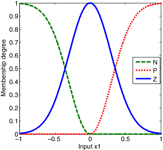
 \begin{align}{\mu _N}({x_1}) & = \left\{ {\begin{array}{c@{\quad}c}0 & x > 0\\[5pt]1 - {\mu _Z}({x_1}) & x \le 0\end{array}} \right.,\nonumber\\[8pt]{\mu _P}({x_1}) & = \left\{ {\begin{array}{c@{\quad}c} 0 & x < 0 \\[5pt]1 - {\mu _Z}({x_1}) & x \ge 0 \end{array}} \right.,\nonumber\\[8pt]{\mu _Z}({x_1}) & = {\textrm{exp}}\left( - \frac{{x_1^2}}{{2{\sigma ^2}}}\right), \sigma = 0.3 \end{align}
These functions are plotted in Fig. 3. Similarly, the membership functions for the input
 ${x_2}$
will be defined. Also, the membership functions for the output
 $\hat h(t)$
are in the form of
 \begin{equation}{\mu _{{D_l}}}(\hat h) = {\textrm{exp}}\left( - \frac{{{{(\hat h - {{\hat y}_l})}^2}}}{{2{\sigma ^2}}}\right)\end{equation}
in which
 ${\hat y_l}$
is the center of
 ${D_l}$
. According to ref. [Reference Izadbakhsh, Khorashadizadeh and Kheirkhahan32],
 $\hat h$
can be represented as
 \begin{equation}\hat h = \sum\limits_{l{{ = 1}}}^9 {{{\hat y}_l}} {\psi _l}({x_1}, {x_{{2}}}) = {\hat y^T}\psi ({x_1}, {x_{{2}}})\end{equation}
where
 $\hat y = {[\begin{array}{c@{\quad}c@{\quad}c}{{{\hat y}_1}} & \ldots & {{{\hat y}_9}}\end{array}]^T}$
and
 $\psi = {[\begin{array}{c@{\quad}c@{\quad}c}{{\psi _1}} & \ldots & {{\psi _9}}\end{array}]^T}$
in which
 ${\psi _l}$
is a positive value expressed as
 \begin{equation}{\psi _l}({x_1}, {x_{{2}}}) = \frac{{{\mu _{{A_l}}}({x_1}){\mu _{{B_l}}}({x_2})}}{{\sum\limits_{l = 1}^9 {{\mu _{{A_l}}}({x_1}){\mu _{{B_l}}}({x_2})} }}\end{equation}
Membership functions for the inputs
 ${x_1}$
.

The controller settings used for the fuzzy system are the same as before. Under these settings, the proposed observer/controller is applied to the robot along with the RBFNN and fuzzy approximator-based controllers.
4.4. Results: Performance evaluation and comparison
To evaluate the controller functioning, three different paths are considered.
Case 1: Simple path
The desired object trajectory is chosen as
 \begin{equation}{{\bf{x}}_{od}}(t) = {\left[ {\frac{{\cos (t)}}{{2(1 + {{\sin }^2}(t))}},\frac{{\cos (t)\sin (t)}}{{2(1 + {{\sin }^2}(t))}} + \frac{{33}}{{20}},0} \right]^T}\end{equation}
The desired internal force level is
 ${{\bf{F}}_{Id}}(t) = {[\begin{array}{c@{\quad}c@{\quad}c@{\quad}c@{\quad}c@{\quad}c}0 & 0 & 0 & 0 & 0 & 0\end{array}]^T}$
. The two 3-DOF arms are initiated at rest, and the joint positions are
 ${\bf{q}} = {\left[ {\begin{array}{c@{\quad}c@{\quad}c@{\quad}c@{\quad}c@{\quad}c}{2.4133} & { - 2.2736} & { - 0.1398} & {0.1398} & {2.2736} & {0.7282}\end{array}} \right]^T}$
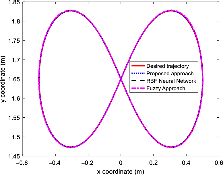
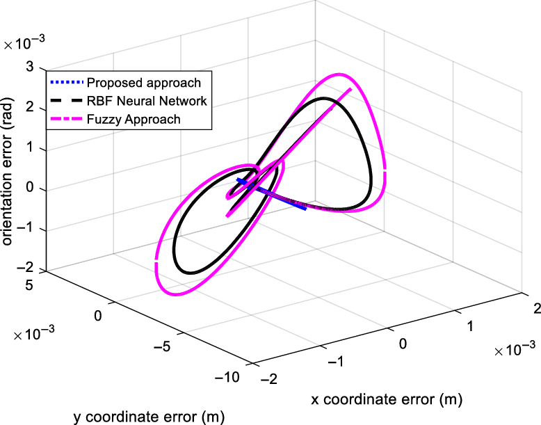
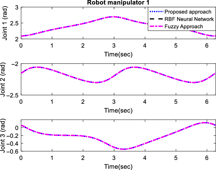
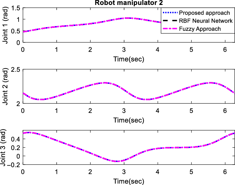
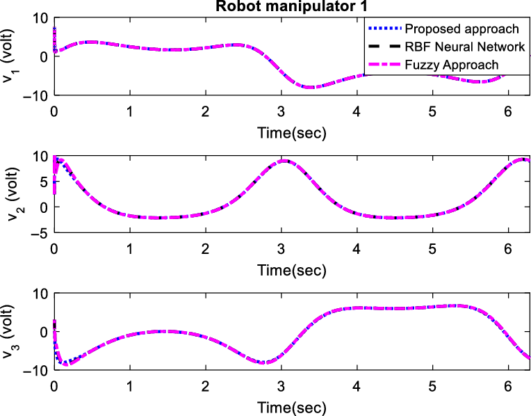
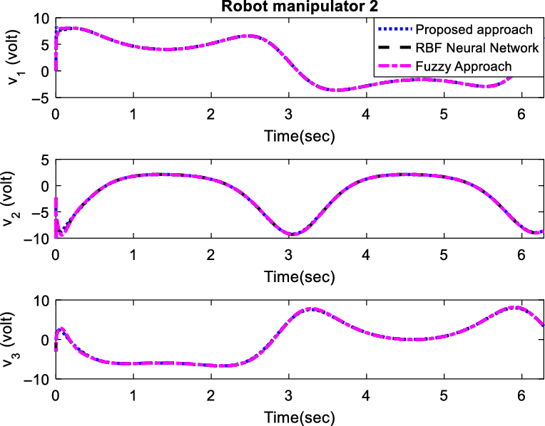
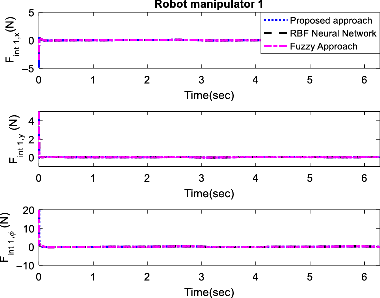
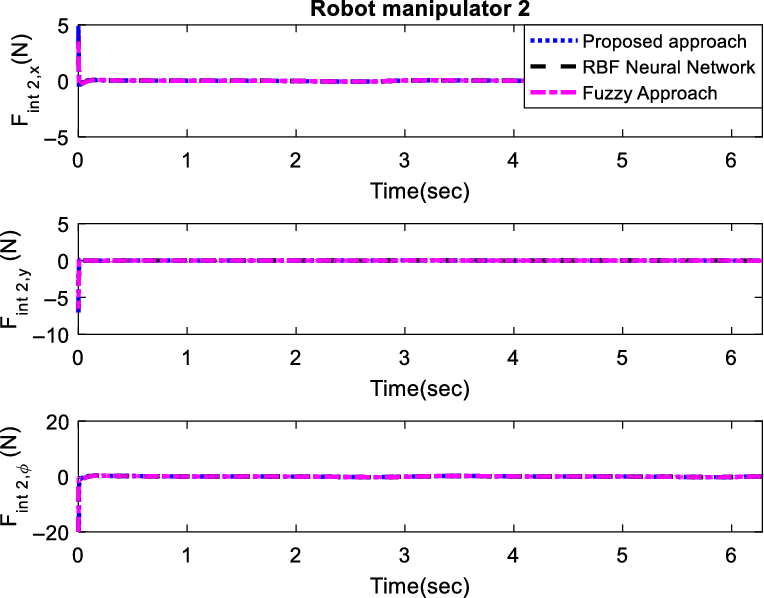
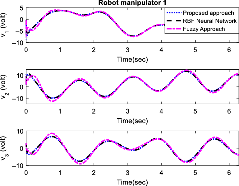
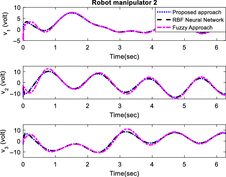
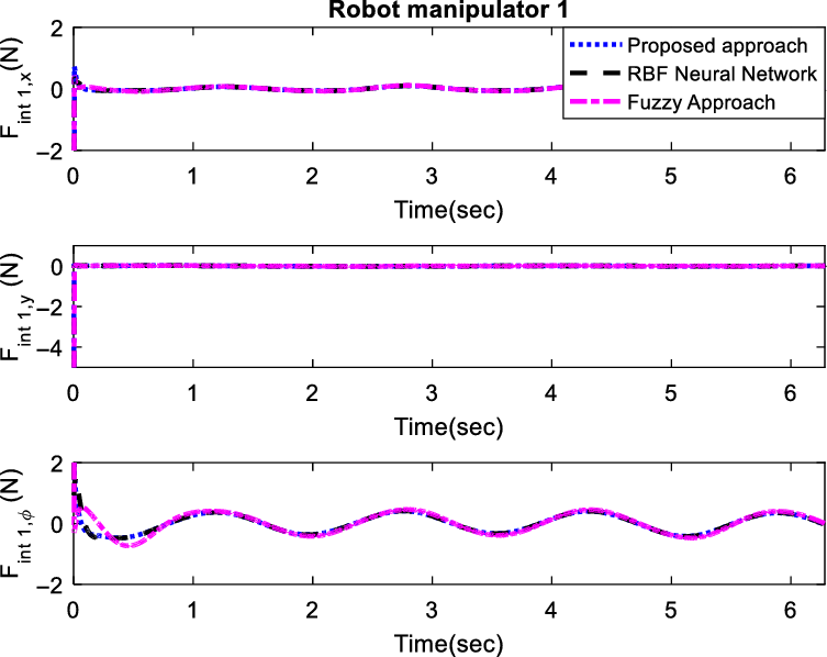
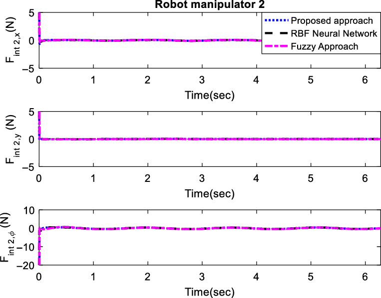
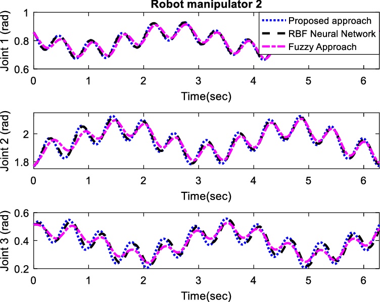
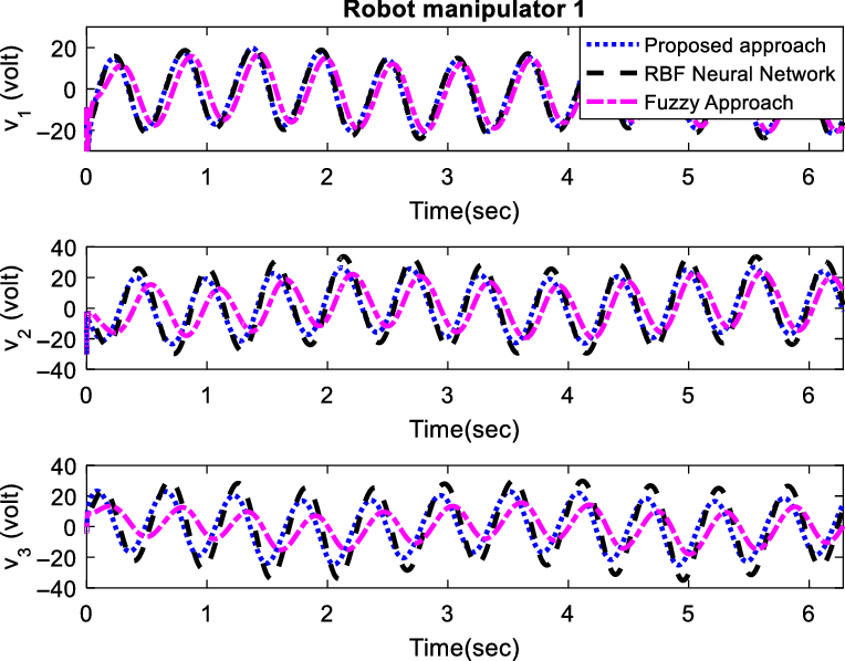
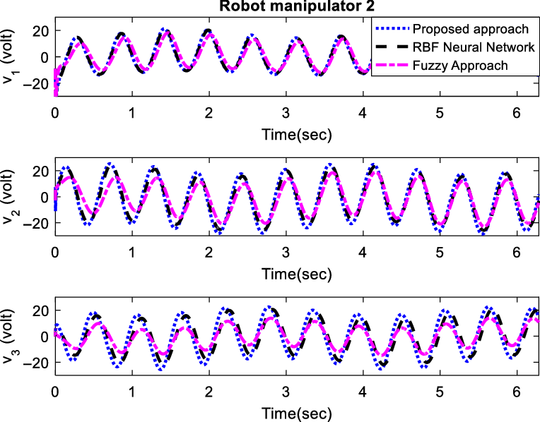
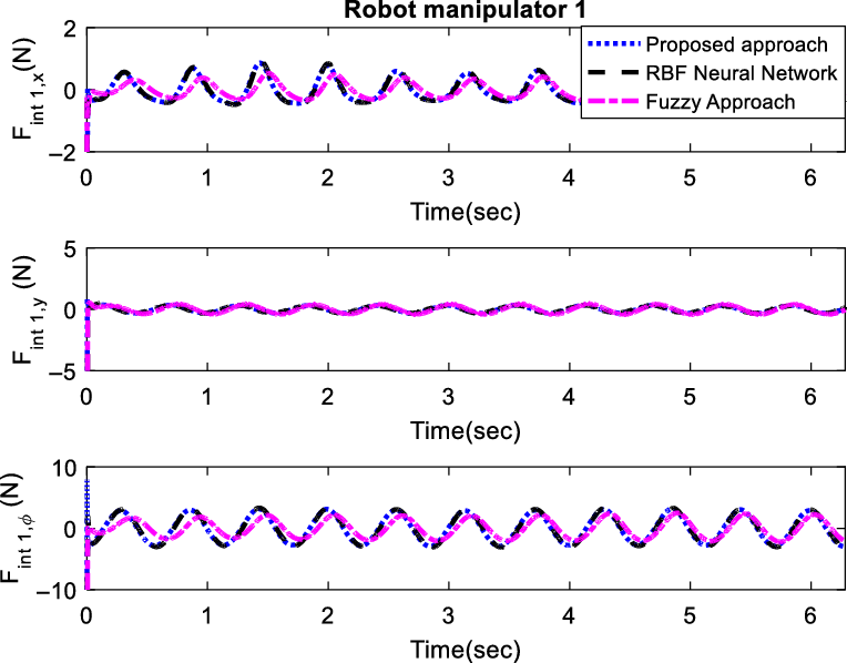
. It is presumed that the initial values of the actual and desired angles are the same. Under these settings, the proposed controller–observer is applied to the robot along with the RBFNN and fuzzy approximator-based controllers. The desired and actual coordinates of the center of the object are illustrated in Fig. 4. According to the figure, despite external disturbances and uncertainties, the manipulator is capable of fulfilling successful trajectory tracking. Figure 5 shows tacking errors related to x and y coordinates and orientation, which are small and UUB. Figures 6 and 7 represent the joint angles for the first and second manipulators, respectively. Figures 8 and 9 illustrate the relative control signals for the robotic arms. According to these Figures, the control signals are bounded and smooth. The internal force tracking results are presented in Figs. 10 and 11. The position and velocity estimation errors have been presented in Figs. 12 and 13, respectively. Figure 14 reveals the approximated lumped uncertainties. According to the figure, all three strategies are capable of exact uncertainty estimation. To show the role of term
 $\hat{\bf{h}}(t)$
in (22), the results are simulated in the absence of it. This condition is indeed the best scenario to examine the system uniformly ultimately bounded stability because the estimation error
 ${{\unicode[varepsilon]{x1D6C6}}_{\bf{h}}}$
is not ignored. That is to say, the estimation error,
 ${{\unicode[varepsilon]{x1D6C6}}_{\bf{h}}}$
has its maximum value in this scenario. Figure 15 show the result of trajectory tracking in this manner.
The object trajectory tracking in the XY plane.

Position and orientation tracking errors.

The angles of the first manipulator joints.

The angles of the second manipulator joints.

Control signals of the first manipulator.

Control signals of the second manipulator.

The internal force of the proposed approach for the first manipulator.

The internal force of the proposed approach for the second manipulator.

The position/orientation estimation error.

The velocity estimation error.

The estimation performance of
 ${\bf{h}}(t)$
.

Trajectory tracking in the absence of
 $\hat{\bf{h}}(t)$
in (22).

Case 2: complex path tracking
To evaluate the efficacy of three observer–controllers, the following desired path is considered.
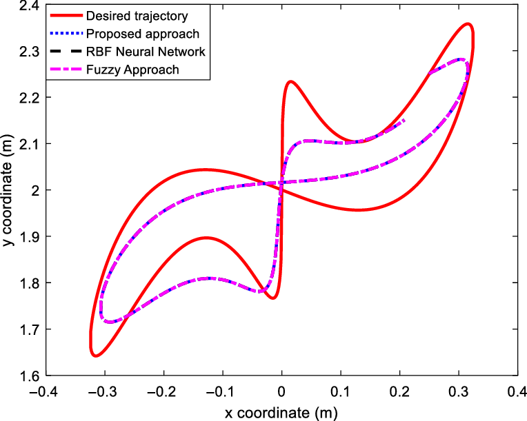
 \begin{equation}{{\bf{x}}_{od}}(t) = {\left[ {\begin{array}{c@{\quad}c@{\quad}c}{0.25\cos (t)(1 + \sin (t))} & {0.25(\cos (t) + \cos (2t)\sin (2t)) + 2} & 0\end{array}} \right]^T}\end{equation}
The joints are assumed to be initiated at
 ${\bf{q}} = \left[ \begin{array}{c@{\quad}c@{\quad}c@{\quad}c@{\quad}c@{\quad}c}{2.446} & { - 1.9717} & { - 0.4743} & {0.4743} & {1.9717} & {0.6956}\end{array} \right]^T $
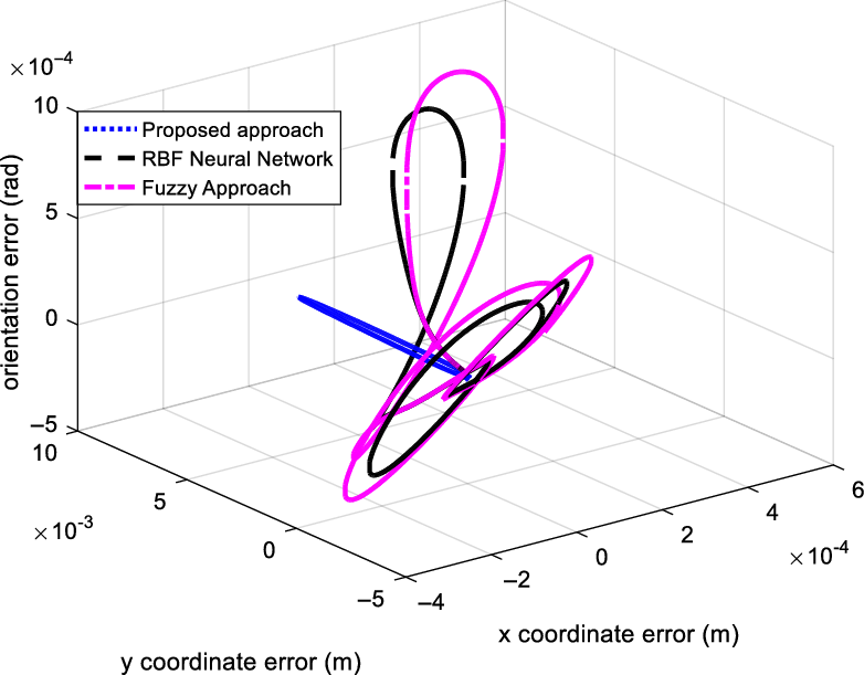
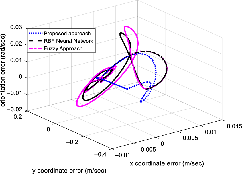
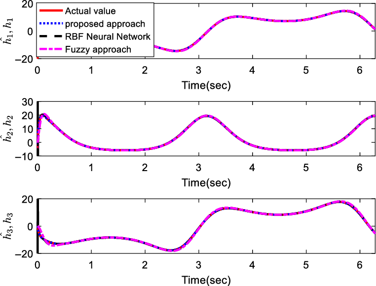
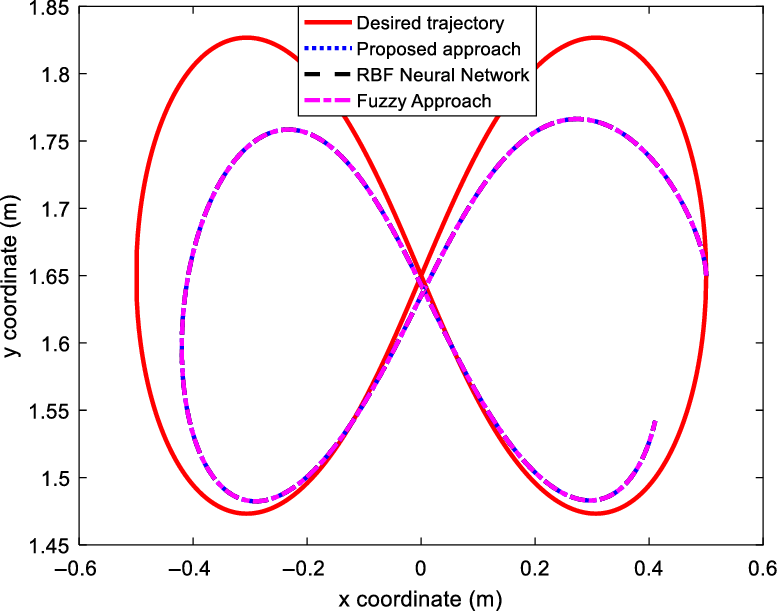
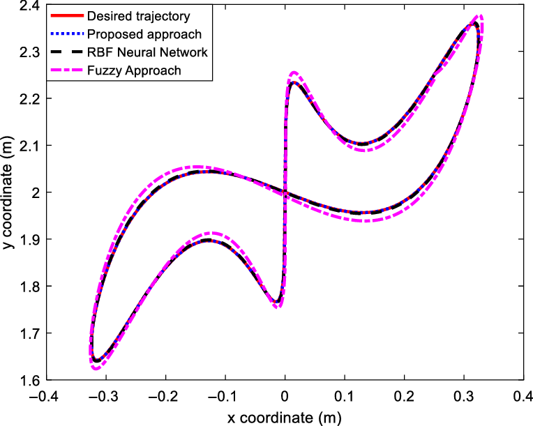
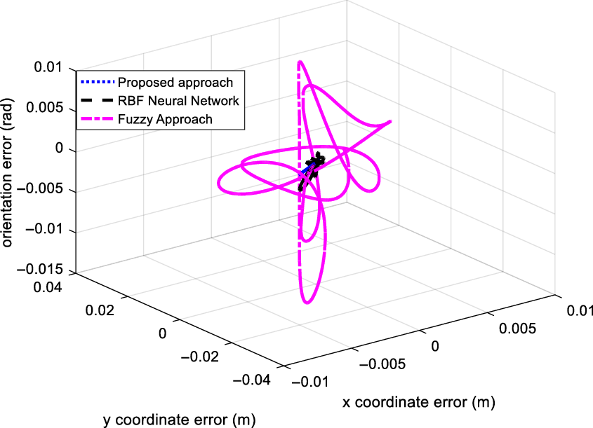
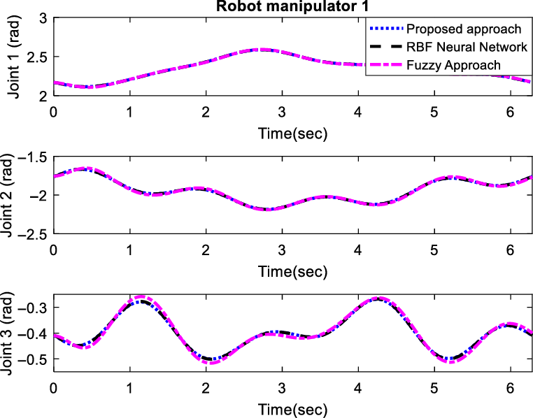
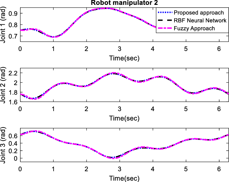
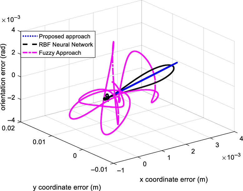
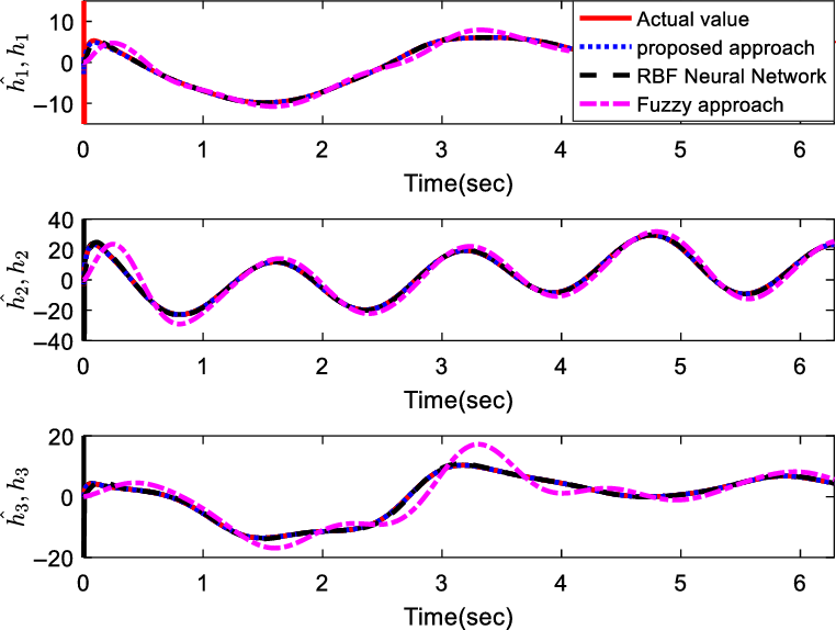
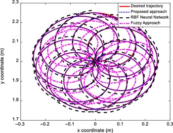
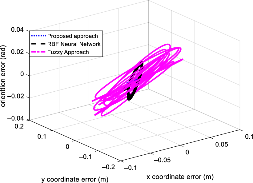
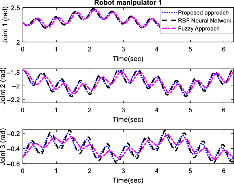
to track the mentioned trajectory. It is supposed that the desired and initial joint positions are the same. All the controller setting are the same as case 1. Figure 16 illustrates the object tracking performance in the XY plane. The x and y-coordinate position errors, as well as the orientation error, are depicted in Fig. 17. Figures 18 and 19 present the joint angles for the first and second robotic arms, respectively. Figures 20 and 21 illustrate the control signals employed to the joint motors by different controller–observer structures. According to these figures, the control signals are smooth and bounded for all applied methods. The trajectory tracking results of the internal forces are illustrated in Figs 22 and 23. The position and velocity estimation errors have been presented in Figs. 24 and 25, respectively. Figure 26 reveals the approximated lumped uncertainties. As the result shows, both RBFNN and the proposed FAT-based strategy have been capable of providing exact uncertainty estimation for the cooperative robotic system; while the fuzzy-based uncertainty approximator have some deviation from actual values. To show the role of term
 $\hat{\bf{h}}(t)$
in (22), the results are simulated in the absence of it. Figure 27 show the result of trajectory tracking in this manner. According to the results, the proposed FAT-based structure can fulfill a good trajectory performance in the existence of uncertainties and external results. The performances of the proposed FAT-based and the RBFNN approximators are nearly the same due to the universal approximation characteristic of these methods. However, there are more adjustable parameters in the regressor vector of the RBFNN (such as the width and center of the Gaussian units), and assigning the best values for these parameters is tedious and time-consuming due to the repeated trial and error. Furthermore, unlike neural network/fuzzy methods, which require system states as inputs to estimate functions and construct a regressor vector, the proposed FAT-based approach is not dependent on the system states. The reason is that these approximators consider the uncertainty as a time-varying function rather than a function of different system states. Besides, the number of system states, as the leading factor in determining the dimension of the basis function vectors, does not affect the FAT-based adaptive control strategy. Hence, the FAT-based controller has a simpler structure and less computational complexity than RBFNN. Besides, the FAT-based approach has a significantly better performance in comparison with the fuzzy approximator. The weakness of the fuzzy method is improvable by increasing the learning rate and the number of basis functions, although it leads to another problem called as the curse of dimensionality. Table II summarizes the merits of the introduced approach in comparison with the RBFNN and the fuzzy system.
The object trajectory tracking in the XY plane.

Position and orientation tracking errors.

The angles of the first manipulator joints regarding the complex trajectory.

The angles of the second manipulator joints regarding the complex trajectory.

Control signals of the first manipulator.

Control signals of the second manipulator.

The internal force of the proposed approach for the first manipulator.

The internal force of the proposed approach for the second manipulator.

The position/orientation estimation error.

The velocity estimation error.

The estimation performance of
 ${\bf{h}}(t)$
.

Trajectory tracking in the absence of
 $\hat{\bf{h}}(t)$
in (22).

The required parameters for the proposed method, RBFNN, and the fuzzy approach.

Case 3: Highly Complex path tracking
To show the capability of three observer–controllers in tasks where precise tracking of fast and highly complex trajectories is required, we used a third desired path generated by
 \begin{equation}{{\bf{x}}_{od}}(t) = \left[ \begin{array}{c}{0.125sin(2t) + 0.125sin(11t)}\\[5pt]2 + 0.125sin\left( {2t + 1.6} \right) + 0.125sin\left( {11t + 1.6} \right) \\[5pt]0\end{array} \right]\end{equation}
where the initial manipulator configuration is as
 ${\bf{q}} = \left[ \begin{array}{cccccc}{2.5607} & { - 1.9798} & { - 0.5809} & {0.5809} & {1.9798} & {0.5809}\end{array} \right]^T$
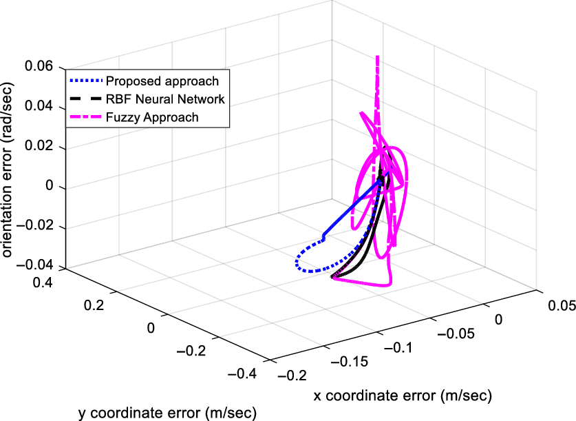
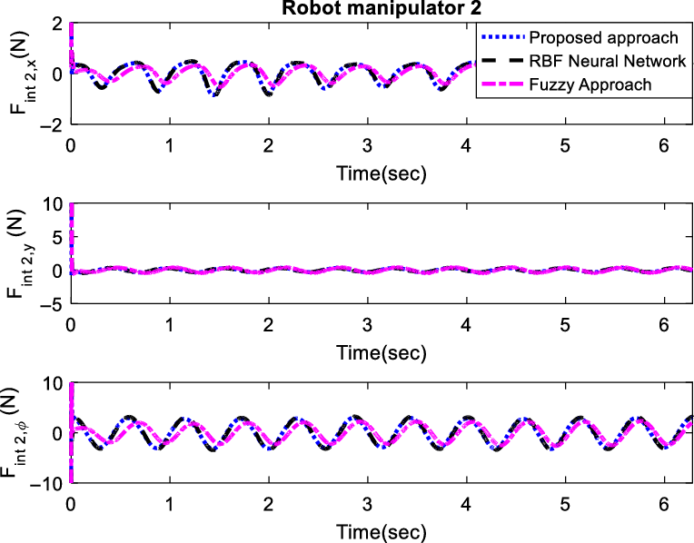
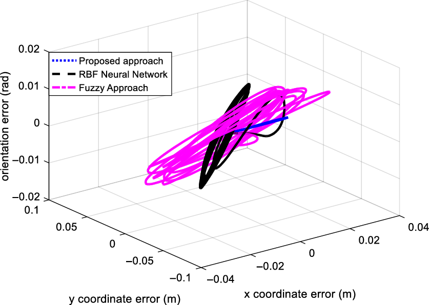
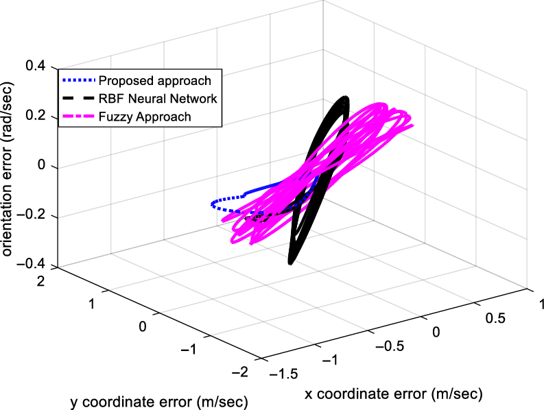
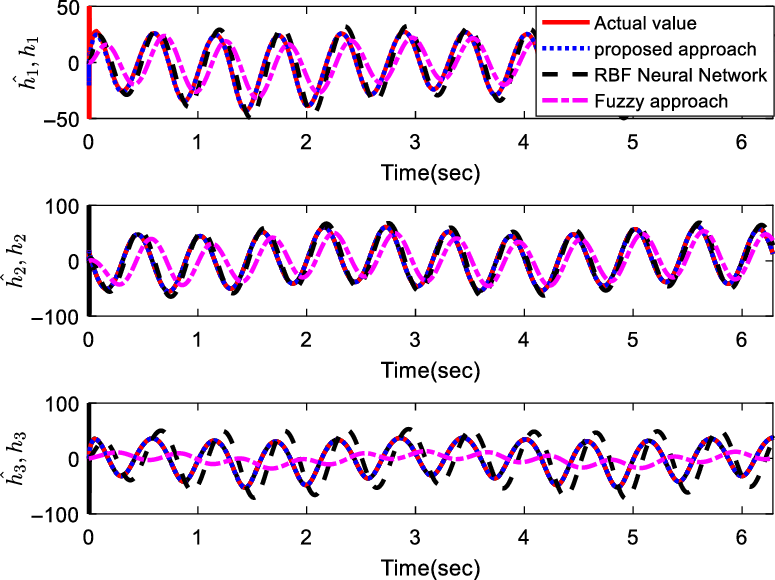
. This trajectory is very important, since it involves rapid and complex reactions between different dynamics of the cooperative robot manipulators. All the simulation settings are chosen the same as those used in the case 1. The results of this simulation are shown in Figs. 28–39. Figure 28 illustrates the object tracking performance in the XY plane. The x and y-coordinate position errors, as well as the orientation error, are depicted in Fig. 29. As can be seen, FAT-based approach has a significantly better performance in comparison with the RBF Neural Network-based uncertainty approximator. The fuzzy approximator, on the other hand, fails to fulfill an acceptable performance. Figures 30 and 31 present the joint angles for the first and second robotic arms, respectively. The control signals are given in Figs. 32 and 33, which are smooth and bounded. The trajectory tracking results of the internal forces are illustrated in Figs 34 and 35. As the results show, the proposed controller has been capable of providing an acceptable performance for the cooperative robotic system, even in the case where no knowledge of the system is in hand. The position and velocity estimation errors have been presented in Figs. 36 and 37, respectively. Figure 38. reveals the approximated lumped uncertainties. According to the figure, the proposed FAT-based strategy is capable of exact uncertainty estimation. It must be noted that the initial jumping in the function approximation can be reduced by choosing suitable value for
 ${\hat{\bf{W}}_{\bf{h}}}(0)$
. To show the role of term
 $\hat{\bf{h}}(t)$
in (22), the results are simulated in the absence of it. Figure 39 shows the result of trajectory tracking in this manner.
The object trajectory tracking in the XY plane.

Position and orientation tracking errors.

The angles of the first manipulator joints regarding the highly complex trajectory.

The angles of the second manipulator joints regarding the highly complex trajectory.

Control signals of the first manipulator.

Control signals of the second manipulator.

The internal force of the proposed approach for the first manipulator.

The internal force of the proposed approach for the second manipulator.

The position/orientation estimation error.

The velocity estimation error.

The estimation performance of
 ${\bf{h}}(t)$
.

Trajectory tracking in the absence of
 $\hat{\bf{h}}(t)$
in (22).

5. Conclusion
In this article, a general robotic system consisting of several robotic arms is considered in which the manipulators move the load cooperatively. It is assumed that the joint velocities are not available, and only the position of the joints can be measured. Therefore, using the Fourier series expansion, an observer–controller is designed for the system that can estimate uncertainties. The stability of the system is completely analyzed by Lyapunov direct method. The results illustrate the boundedness of system errors. The proposed method is regressor-free, and therefore, it does not have the problems of adaptive approaches. One of the advantages of the proposed method is being model-free that makes it robust in confronting the unmodulated dynamics. It is worth noting that, in this method, there is no need to know the bounds of uncertainties. Also, unlike many common control approaches, in this article, the voltage signal is considered as the control signal instead of the torque, and the actuator dynamics are not neglected. To evaluate and analyze the performance of the adaptive FAT-based controller, it is applied to two 3-DOF cooperative robotic arms. The results indicate the robustness of the introduced approach against unmodulated dynamics and perturbations.