1. Introduction
Human–robot interaction (HRI) system enables human operators to work together with the robot, and has a great potential for improving production efficiency [Reference Villani, Pini, Leali and Secchi1, Reference Aspragathos, Moulianitis and Koustoumpardis2]. Compared with traditional robotic manufacturing systems [Reference Krüger, Lien and Verl3], the HRI system allows human operators to work together with the robots without time or space separation. In an HRI team, the operators can provide better problem-solving skills, whereas robots have better strength and accuracy. The manufacturing efficiency can be further improved by utilizing advantages from both operators and robots.
With the rapid development of the new manufacturing modes, however, the existing HRI systems [Reference Liu, Ge, Zhao and Mei4, Reference Glogowski, Böhmer, Alfred and Bernd5] cannot meet the requirements of complex tasks, which only allow one operator to interact with the robot. Recently, multihuman–robot interaction (MHRI) rises to a vital research topic in the field of robotics applications [Reference Mina, Kannan, Jo and Min6]. Compared with the single HRI, the involvement of multiple humans can improve the flexibility of robot control and task assignment, which is an important advantage of the MHRI system. However, the involvement of multiple humans comes with new challenges, such as multihuman 3D pose estimation and pose occlusion. The recent works have made progress in safety [Reference Xia, Jiang and Zhang7, Reference Yasar and Iqbal8], task allocation [Reference Alevizos, Bechlioulis and Kyriakopoulos9–Reference Bänziger, Kunz and Wegener11], and perception [Reference Patel and Pinciroli12, Reference Xu, Yu, Wang and Ou13] for the MHRI system. However, there remain challenges in the integration of the real-time MHRI system, primarily due to the uncertainty and diversity of human beings as well as the tasks, which lead us to investigate the general dynamic MHRI system.
Ensuring the safety between the operators and the robots (human–robot safety) is the key to the HRI system. Many researchers have proposed sensor-based safety systems [Reference Morato, Kaipa, Zhao and Gupta14, Reference Nascimento, Mujica and Benoussaad15]. By utilizing the monitoring capability of depth sensors, the distance between human operators and robots can be actively monitored. Robots can also be controlled to stop if the distance between human operators and robots is too close. However, these approaches will decrease the efficiency of collaborative assembly, as the robots will frequently move away and stop during the assembly process. To solve the problem of the safe shutdown, researches on human behavior prediction [Reference Abdel-Malek, Mi, Yang and Nebel16, Reference Callens, van der Have, Van Rossom, De Schutter and Aertbeliën17] have been conducted based on context awareness. That is, the robot perceives the operator to avoid collision in advance by predicting the joint position of the operator in a certain period in the future. To realize a more safety and efficient MHRI system, in this study, researches on human–robot pose perception and robot interactive control are required.
Human–robot pose perception includes monitoring the movement of the robot and multiple human 3D pose estimation. For the fixedly installed robot, the pose can be determined with robot hand-eye calibration [Reference Liu and Wang18]. For multihuman 3D pose perception, in the previous works [Reference Morato, Kaipa, Zhao and Gupta14, Reference Mohammed, Schmidt and Wang19], the Kinect depth camera has been widely used for human 3D body estimation. However, human joints position read directly based on depth information will cause depth value ambiguity by occlusion. To solve the occlusion problem, multiview human 3D pose fusion methods [Reference Recchiuto, Sgorbissa and Zaccaria20, Reference Fortunati, Cavallo and Sarrica21] are proposed to estimate more accurate poses. However, due to extensive computation amount of multiview information fusion, the real-time performance is poor with the increasing number of people. With the development of deep learning in recent years, image-based 3D poses estimation methods have also made significant progress. Specifically, deep learning-based multihuman 3D pose estimation methods are divided into two broad categories: top–down [Reference Zanfir, Marinoiu and Sminchisescu22–Reference Benzine, Chabot, Luvison and Achard24] and bottom–up [Reference Zanfir, Marinoiu, Zanfir, Popa and Sminchisescu25–Reference Fabbri, Lanzi, Calderara, Alletto and Cucchiara28]. Top–down approaches of multihuman 3D pose estimation first perform human bounding boxes detection for each individual. Then for each detected person, absolute root coordinate and 3D root-relative pose are estimated by 3D pose networks. A camera distance-aware approach in ref. [Reference Moon, Chang and Lee23] shows that the cropped human images were fed into their developed RootNet to estimate the camera-centered root coordinates of the human body. Then the root-relative 3D pose of each cropped human was estimated by the proposed PoseNet. However, the computational complexity and the inference time of top–down methods may become excessive as the number of people increases, especially in crowded scenes. On the contrary, the bottom–up approaches enjoy smaller computation and time complexity. These approaches first produce all body joint locations, and then associate body parts to each person. A key challenge of bottom–up approaches is how to group human body joints which belong to each individual. A distance-based heuristic was developed in ref. [Reference Fabbri, Lanzi, Calderara, Alletto and Cucchiara28] for connecting joints in the multiperson context. Starting from the detected head, the full 3D pose is linked by selecting the closest ones in terms of 3D Euclidean distance. However, the process of multihuman pose estimation can only obtain the joint position. In MHRI scenarios, there are often unrelated persons in the view field, which will affect the stability of interaction. Skeleton-based action recognition methods were adopted, given their robustness to illumination change and scene variation [Reference Song, Yin, Yuan, Zhang, Chi, Ling and Zhang29, Reference Shotton, Sharp, Kipman, Sharp, Finocchio, Moore and Blake30]. The operator and other persons can be distinguished by their detected actions during the interactive process.
Excepting the information perception of the human and robot, motion planning and control technologies are also vital for adapting reactive changes in the HRI context. The robot should react more dynamically to the presence of people and changes in the environment. Some studies [Reference Kulić and Croft31–Reference Wang, Wei, Yeboah, Li and Gao34] tend to modify the robot tasks based on current HRI about the system. Typical approaches apply virtual repulsive forces to the robot to move it away from the operator [Reference Nascimento, Mujica and Benoussaad15, Reference Flacco, Kröger, De Luca and Khatib33]. These methods are fast and reactive but are suboptimal. Recently, some novel control methods [Reference Wang, Wei, Yeboah, Li and Gao34–Reference Sathya, Gillis, Pipeleers and Swevers36] were proposed to generate motion trajectory, which add the environmental constraints based on model predictive controller (MPC) controller (such as distance between the obstacle and the robot [Reference Sathya, Gillis, Pipeleers and Swevers36]). Compared with the former, the results of MPC using sampling and optimization are optimal but not fast enough to react to the changes in the environment in real time. The proximal averaged Newton-type optimal control (PANOC) algorithm is applied to the MPC framework to solve the problem of optimal cost [Reference Sathya, Sopasakis, Van Parys, Themelis, Pipeleers and Patrinos37, Reference Small, Sopasakis, Fresk, Patrinos and Nikolakopoulos38]. Further, an augmented Lagrangian method (ALM) [Reference Sathya, Gillis, Pipeleers and Swevers36] was employed to deal with hard constraints for realizing robot manipulator motion planning and control. However, the randomness of task targets and changes frequently of work scenes are not fully considered in the interactive process. The control reliability of the robot is difficult to guarantee in a dynamic environment.
To achieve a safe and efficient MHRI system, this study focuses on multihuman 3D pose perception and robot control strategy. For multihuman 3D pose estimation, a real-time monocular 3D pose estimator is designed based on the convolutional neural network. A set of 2D joints representations of body parts are regressed at first, and then the 3D joints positions are restored at these 2D joints pixel locations. These 3D joints are assigned to the corresponding individual with a priority–redundancy association algorithm. Our algorithm has good robustness even in the case of severe occlusion. To solve the interference problem of other people in the interactive process, an operator and nonoperator recognition algorithm is proposed based on action recognition and skeleton tracking to recognize the identity of each person for effectively interacting with the robot. In our studies, the nonoperator is defined as nontask demanded personnel during the interactive process and interfering personnel in the field of view. Besides, combined with the robotic kinematics, the robot interactive control strategy is designed based on target point generation and correction. The task point is fed into the low-level MPC controller as a reference to generate a trajectory and realize the interaction between the robot and multiple persons. The designed control strategy can improve adaptability of the robot for multiple tasks. In the end, the experiments of safe interaction and cooperative carrying are designed to verify the feasibility and effectiveness of the MHRI system by some related metrics.
Our contributions include:
-
1. A novel MHRI system is presented for contactless MHRI. Compared with the single HRI system, our MHRI system has better adaptability to complex environments.
-
2. We propose a lightweight monocular multihuman 3D pose estimator with a convolutional neural network, which has good real-time performance and occlusion solving ability. The network adopts multiple branches architecture and outputs the 2D/3D joint positions simultaneously. At the end of the network, a priority–redundancy association algorithm is presented for reasoning about inter-person occlusion and grouping the 3D joints to corresponding individuals.
-
3. A novel algorithm is proposed for identifying the operator and nonoperator based on action recognition and 3D skeleton tracking to ensure that the robot can correctly interact with each person in the scene. Multiple persons can be recognized correctly, even in the occlusion context or loss pose information.
-
4. For multitask requirements, a flexible interaction strategy is proposed based on target task generation and correction. We also implement an ALM on top of the PANOC algorithm to enforce the robot state constraints for reducing the tracking error of the robot. Besides, the flexible interaction is achieved through adjusting the penalty coefficients according to different task requirements.
The remainder of this study is organized as follows: In Section 2, the overall MHRI system is introduced. In Section 3, the methods of human–robot motion capture are presented in detail. In Section 4, the strategy of robot control is designed. Subsequently, experiments and results are shown in Section 5. The study ends with a conclusion in Section 6.
2. MHRI System Design
2.1. Description of multihuman–robot interactive task
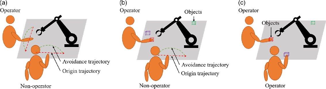
In the MHRI system, the robot assists the operators in executing tasks as a partner. Figure 1 gives three typical contactless MHRI tasks, such as dynamic obstacle avoidance (human–robot safety) and collaborative assembly. The HRI is realized through the robot tracking the target points generated by different tasks. The tasks in Fig. 1 are described in detail as follows:
Description of the typical multi-human robot interactive tasks.

-
(1) For the multihuman–robot safety task, all people are regarded as obstacles, the robot should take the initiative to avoid them. As shown in Fig. 1(a), when the operators enter the workspace of the robot, the robot slows down to avoid the operator by replanning the trajectory actively.
-
(2) For the multihuman–robot collaborative tasks, both operators and nonoperators may exist simultaneously. As shown in Fig. 1(b), there are an operator and a nonoperator. The operator and the robot cooperate to complete the same task (carrying objects), whereas the safety between nonoperators and the robot should be guaranteed.
-
(3) In the multihuman–robot collaborative tasks, multiple operators may also exist at the same time. As shown in Fig. 1(c), the robot completes the task together with multiple operators to further improve efficiency.
2.2 System architecture design
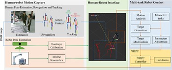
Theflowchart of the proposed system mainly consists of three parts, namely human–robot motion capture, multitask robot control, and human–robot interface, as shown in Fig. 2. The human–robot motion capture includes the multihuman pose estimation, recognition and tracking, and the robot pose estimation. The robot pose is estimated with robotic kinematics and hand-eye calibration, while the multiple human 2D/3D poses are estimated by the pose estimator from RGB image streams with neural network. The 2D pose of each person is employed to recognize the operators by the pose action. Then, the operators and nonoperators are tracked using the 3D poses and their initial identities in consecutive frames to achieve reliable HRI. The human–robot interface stores the current human–robot pose, analyzes the relative spatial relationship, and plays the role in synchronization and visualization. The multitask robot control part includes the interactive strategies and robot controller design. The interactive strategy includes three interactive tasks as shown in Fig. 1. According to different interaction modes, the corresponding task goal is generated. Then the goal is taken as a reference to the model predictive controller (MPC) based on constraints for updating the state of the robot, and the states updated are sent to the real robot to complete the interactive behavior.
Our multi-human robot interaction system structure.

The overall MHRI system is developed based on the robot operating system (ROS) middleware [Reference Quigley, Conley, Gerkey, Faust, Foote, Leibs and Ng39]. Each part of the MHRI system communicates by receiving and publishing topic messages. As the top-level module, human–robot motion capture perceives the spatial information of multiple humans and the robot in the MHRI scene through a camera, and outputs the 3D pose position and identity of each person, and each joint spatial position of the robot. Then, the human–robot interface inputs the 3D pose of each individual and the robot, and outputs the spatial position relationship of each person relative to the robot by analyzing the geometric distance. At the end, as the bottom-level control module, the multitask control part takes the relative position of the robot to each person and interactive task mode as the inputs to generate the task target goal. The goal is taken as a reference to the MPC so that the motion instructions could be generated to complete the interactive behavior. At this time, the updated robot state will be fed back to the robot estimation part in the human–robot motion capture, thus forming a closed loop.
3. Human–Robot Motion Capture for MHRI
3.1. Calibration
Calibration is the basis for the MHRI system. There are three types of calibration: camera intrinsic calibration, camera extrinsic calibration, and robot hand-eye calibration. Monocular sensor intrinsic parameters can be calibrated by ref. [Reference Yang, Yan, Dehghan and Ang40], which will provide quality images for the HRI system. Robot hand-eye calibration renders the collected images according to the robot location [Reference Liu and Wang18, Reference Rakprayoon, Ruchanurucks and Coundoul41]. The calibration process will determine the position and orientation of the robot with respect to the camera. The camera extrinsic matrix calibration process is to calculate the transformation of the camera in the world coordinate.
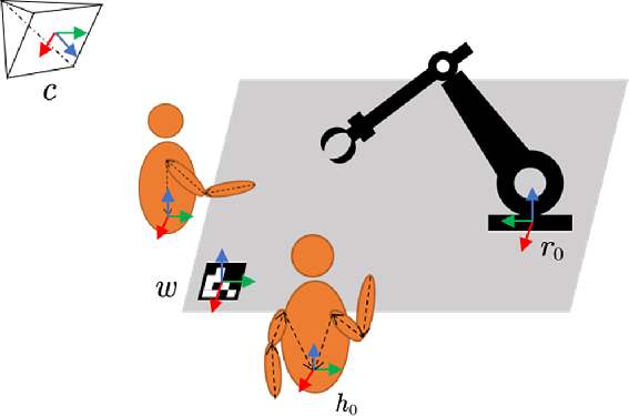
The outline of the coordinate description is shown in Fig. 3. Assume that w is the world coordinate, c is the camera coordinate, r
0 is the base coordinate of the robot, and h
0 is the root joint of the human operators. For the fixed robot and the camera, the transformation matrix
 $T_{r_{0}}^{c}$
can be calculated by the above robot hand-eye calibration. The monocular extrinsic matrix
 $T_{c}^{w}$
is also directly read by OpenCV ToolkitsFootnote
1
, which represents the transformation of camera c with respect to the world coordinate w. Then, the transformation
 $T_{r_{0}}^{w}$
of the base coordinate of the robot to world coordinate can be expressed as below. The transformation
 $T_{{r_0}}^w$
is a constant matrix, so that the repeated and complicated hand-eye calibration process caused by the movement of the robot or camera can be avoided.
 \begin{align} T_{{r_0}}^w = T_c^wT_{{r_0}}^c \end{align}
Description of the coordinates in the MHRI system. The coordinates of camera c and the robot base r 0 are represented under the world coordinate ω. The human root joint h 0 is indicated under the camera c, the other joints of the human body are denoted based on the root joint h 0. Similarly, the other links of the robot are denoted with respect to the robot base r 0. The whole coordinate structure looks like a tree.

3.2. Representations of multihuman and robot poses
In our MHRI system, the robot can be regarded as a series rigid body link motion system. The parent link and the child link are connected by a single degree of freedom (DOF) rotary joint. Through the forward kinematics of the robot, the sublink coordinate can be interfaced from the base coordinate. The transformation
 $T_{{r_i}}^{{r_0}}$
between any sublink r
j
and the base r
0 can be expressed as follows:
 \begin{align}T_{{r_j}}^{{r_o}} = \prod\limits_{x = 1}^j {T_{{r_x}}^{{r_{x - 1}}}\left( {{\theta _{{r_x}}}} \right) = \prod\limits_{x = 1}^j {\left[ {\begin{array}{*{20}{l@{\quad}l}}{R_{{r_x}}^{{r_{x - 1}}}}({{\theta _{{r_x}}}}) & {}{t_{{r_x}}^{{r_{x - 1}}}}\\0 & {}1\end{array}} \right]} } \end{align}
where
 ${\theta _{{r_x}}}$
is the joint angle between sublink r
x
and parent link r
x−1
,
 $R_{{r_x}}^{{r_{x - 1}}}$
and
 $t_{{r_x}}^{{r_{z - 1}}}$
are the rotation matrix and translation vector of sublink r
x
to its parent link r
x−1
.
Then, the transformation
 $T_{{{r}_i}}^w$
of any sublink r
j
with respects to the world coordinate w can be indicated as follows:
 \begin{align}T_{{{r}_j}}^w = T_{{r_0}}^wT_{{r_j}}^{{r_0}}\end{align}
The multihuman 3D poses are composed of the corresponding joints set, which are represented by the root joint h
0
. Similar to the robot, the transformation
 $T_{{h_j}}^{{h_0}}$
between any human joint h
j and the root joint h
0
can be expressed as follows:
 \begin{align}T_{{h_j}}^{{h_0}} = \prod\limits_{n = 1}^j {\left[ {\begin{array}{*{20}{c@{\quad}c}}{{I_3}} {}& {t_n^{{h_{n - 1}}}}\\0 & {}1\end{array}} \right]} \end{align}
where I
3 is the identity matrix.
 $t_{{h_n}}^{{h_{n - 1}}}$
is the translation vector of joint h
n
to its parent joint h
n−1
.
The human skeleton structure is not fully connected in series compared to the robot. The length of
 $\prod _{n = 1}^j\left(. \right)$
depends on the number of body limbs from joint h
j
to root h
0
. For example, the number of limbs (draw by black lines in Fig. 3) from the wrist joint to the root joint is 3.
In the same way, the position of the human joints should also be expressed in the world coordinate. Supposed that
 $p_{{h_j}}^{{h_0}}$
represents the position of joint h
j
expressed by h
0
, the joint position
 $p_{{h_j}}^w$
in world coordinate can be calculated as follows:
 \begin{align}p_{{h_j}}^w = T_c^wT_{{h_o}}^cT_{{h_j}}^{{h_0}}p_{{h_j}}^{{h_0}}\end{align}
where
 $p_{{h_j}}^w$
,
 $p_{{h_j}}^{{h_0}}$
are the homogeneous representation of j
th joint by[X,Y,Z,1].
3.3. Real-time multihuman 3D pose estimation based on CNN
In this stage, we propose a monocular multihuman 3D pose estimator based on CNN for estimating the human joints position in the MHRI system. First, the source of ideas behind the work is explained and then the proposed method is described in detail, including the network structure, loss function and association algorithm. Through researches on some previous works [Reference Zanfir, Marinoiu and Sminchisescu22, Reference Moon, Chang and Lee23] of multihuman 3D pose estimation, we find that for different 3D pose estimators, the real-time performance and the occlusion processing capability are rarely available simultaneously, whereas both should be required in our MHRI system. Therefore, we use a lightweight backbone network to extract features to reduce network reasoning time. Aiming at the occlusion problem, we propose a priority–redundancy association algorithm to allocate the joint position of the network regression for obtaining the full 3D pose.
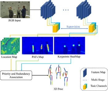
Figure 4 presents the flowchart of our bottom–up approach. Taking an RGB image as input, the network outputs the 2D representations, including keypoint heatmaps and part affinity fields (PAFs) [Reference Cao, Hidalgo, Simon, Wei and Sheikh42], and 3D location maps [Reference Mehta, Sotnychenko, Mueller, Xu, Sridhar, Pons-Moll and Theobalt43]. Then, a priority–redundancy association algorithm is proposed to assign detected 2D keypoints, and 3D location maps to individuals. Our network allows to read fully 2D and 3D poses even in severe occlusion.
Schematic diagram of multihuman 3D pose estimation. Given an RGB image, the network regresses several intermediate representations including 2D keypoint heatmaps, part affinity fields(PAFs), location maps. With a new priority–redundancy association algorithm, body parts belonging to the same people are linked to get fully 3D pose.

3.3.1. Network architecture
We use the lightweight MobileNet V3 [Reference Howard, Sandler, Chu, Chen, Chen, Tan and Adam44] as the backbone network and modify it to a multitask structure with multiple branches that output the following representations as illustrated in Fig. 4. There are two output branches of the network. The 2D pose branch simultaneously regresses keypoint heatmaps and PAFs, while the 3D pose branch regresses the location map. Given an RGB image I, getting the feature matrixes through the lightweight backbone and feeding it into the 2D branch to obtain the heatmaps H and PAFs C based on convolutional pose machines [Reference Wei, Ramakrishna, Kanade and Sheikh45]. Then, the feature matrixes and the 2D heatmaps are inputted into the 3D branch network with ResNet block [Reference He, Zhang, Ren and Sun46] to regress the location maps M at these 2D pixel location. Besides, we supervise the location maps between different stages to reduce the dependence of the network on the large labeled dataset. Supposed the predefined joints number is N, the network will output a fixed number of maps, including N heatmaps, 2N PAFs, and 3Nlocation maps. The output representations are described as follows:
-
HeatMap The possible pixel locations of human joints in the image. The 2D poses set of all human is defined as
 $P^{2D} = \left\{p_{i}|p_{i}\epsilon\mathbb{R}^{N\times{3}}\right\}$
(i is the index of human). Each pose p
i
includes 15 joints. Each joint
$p_i^j$
contains the corresponding pixel coordinates
$\left( {x_i^j,y_i^j} \right)$
and confidence
$\alpha _i^j \in \left[ {0,1} \right]$
, where j is the index of joints. The confidence represents the joint evaluation by the neural network. If
$\alpha _i^j = 0$
, the joint is considered undetected.
-
Part affinity field (PAFs) PAFs proposed in ref. [Reference Cao, Hidalgo, Simon, Wei and Sheikh42] include a set of 2D association vectors, which assign the detected 2D joints to the corresponding person correctly. Each vector represents the 2D orientation of the body part at the joint pixel location.
-
Location Map Location map is a joint feature channel used to store the 3D coordinates at the 2D pixel location [Reference Mehta, Sridhar, Sotnychenko, Rhodin, Shafiei, Seidel and Theobalt47]. For each joint, three maps represent the corresponding estimated x, y, z coordinates. For an image of size
$W \times H$
,
$3n$
maps of size
$W/k \times H/k$
are used to store the 3D positions of all n joints, where k is the down-sampling factor. The 3D pose of each person is denoted as M
i
. Each joint
$M_i^j$
is composed of corresponding
$\left( {x_i^j,y_i^j,z_i^j} \right)$
coordinates.


3.3.2. Loss function
As shown in Fig. 4, we construct the loss function based on the 2D and 3D poses and supervised process. The L 2 loss is applied to all branches during training. The 2D pose loss L 2D is the pixel location error obtained by the heatmaps and PAFs with the ground truth in the image I. The 3D pose loss L loc is the joint error calculated by the 3D location maps and the ground truth. The supervised loss L sup is the 3D location maps error at different stages. The total loss L total is expressed as follows:
 \begin{align}\begin{array}{*{20}{l}}{{L_{total}} = {w_{2D}}\cdot{L_{2D}} + {w_{loc}}\cdot{L_{loc}} + {w_{sup}}\cdot{L_{sup}}}\\{{L_{2D}} {} = \sum\limits_{i = 1}^N {\sum\limits_{p \in I} {||{H_i}(p) - H_i^*(p)||_2^2} } + \sum\limits_{i = 1}^{2N - 2} {\sum\limits_{p \in I} {||{C_i}(p) - C_i^*(p)||_2^2} } }\\{{L_{loc}} = \sum\limits_{i = 1}^N {\sum\limits_{p \in I} {||{M_i}(p) - M_i^*(p)||_2^2} } }\\{{L_{loc}} = \sum\limits_{i,j\,(i\,\neq\,{j})}^S {{||{M_i} - {M_j}||_2^2} } }\end{array}\end{align}
where N and S are the number of joints and network stage, respectively, p means each pixel location and superscript * denotes the ground truth.W 2D , W loc , and W sup are the penalty coefficients.
3.3.3. Priority–redundancy part association
Given 2D coordinates of keypoints from heatmaps and 3D location maps, we need to associate detected joints with corresponding individuals. Taking the PAF score directly to allocate joints, the pose is unreliable due to occlusion. In the inference process, since the number of people in the input image is unknown, we use the root depth maps to reflect the operator number. Generally, the torso joints (neck and hip) in the middle of the body are not occluded, which are the best choices for the root joints. In this study, the neck joint of the human body is regarded as the root joint. If the root joint of an individual is visible, we continue to assign the joint to the person. Otherwise, this person is not visible in the scene, and the pose cannot be predicted. The inference process is outlined in Algorithm 1.

To solve the occlusion problem, we give priority to the unoccluded people when assigning joints. The occlusion state can be inferred in the depth map (location map Z-channel) predicted by the network. The root depth value represents the absolute position of each person. Therefore, the priority of each people is sorted by the predicted root depth from near to far, rather than the PAF score. Note that our network allows reading the position of the limb from any 2D joint of the corresponding limb [Reference Mehta, Sotnychenko, Mueller, Xu, Sridhar, Pons-Moll and Theobalt43]. For individual i, the basic pose
 $P_{base}^{3D}$
is first read at the root joint, which is regressed by an average pose in datasets [Reference Joo, Simon, Li, Liu, Tan, Gui and Sheikh48]. Then, we continue to read the limb pose from the joint close to the root to obtain the full 3D pose
 $P_i^{3D}$
. If the joint is valid, the limb pose replaces the joints of the base pose. Otherwise, going down the kinematic chain to check other joints of this limb. If all joints of the limb are invalid, the limb pose cannot be refined. In the end, another refinement method is presented for reducing error further based on the camera model. Given visible 2D coordinates (x,y) and joint depths Z, the 3D joints can be recovered through the perspective camera model as follows:
 \begin{align} {[X,Y,Z]^T} = Z{K^{ - 1}}{[x,y,1]^T}. \end{align}
where
 $[X,Y,Z]$
and
 $\left( {x,y} \right)$
represent the 3D and 2D coordinates of the joint, respectively, K is the camera intrinsic matrix.
In summary, the pose estimator will output the 2D and 3D poses of each person in each frame in this process. Each pose consists of corresponding joints set. The 2D pose includes the joint pixel coordinates and confidence. The 3D pose includes the space position of each joint relative to the root joint. The coordinates are all expressed in camera coordinate c, which provide essential information for subsequent identification for operators and nonoperators.
3.4. Multihuman action recognition
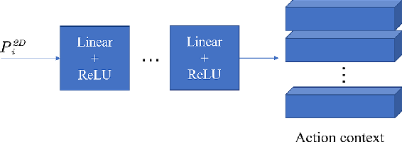
Considering that there may be both operators and nonoperators in the MHRI process, the motion trajectory of the robot will be affected by them. In this stage, the behavior of each person is predicted through the action classification model, which is employed to recognize operators and non-operators in the MHRI scene. As shown in Fig. 5, the action recognizer is composed of five linear layers and the ReLU activation function. The input of the network is the 2D joint pixel location, and the output is the corresponding action label.
 \begin{align}l = f(P_i^{2D},\xi )\end{align}
where l is the output action label,
 $P_i^{2D}$
represents the 2D pose of the person i, and
 $\xi$
is the predefined action label set.
Schematic diagram of action classification. Given a 2D pose, the linear network will output the corresponding action context.

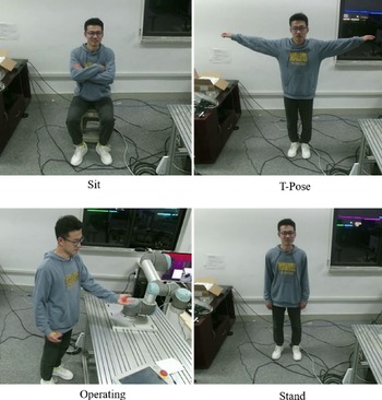
The interactive actions of HRI are different from daily actions. In this study, four kinds of actions are set according to the task requirements, which are named “T-Pose”, “Sit”, “Stand”, and “Operate”, respectively. Operators and nonoperators are distinguished by T-Pose, whereas other actions are applied to monitor the status of each people during the interactive process. In the recognition process, the operator should cooperate with the recognizer by posing the T. The action recognizer assigns the identity for each person according to the current action of each person. Note that the T-pose action is only valid once and the number of operators should be set in advance according to the task requirements.
3.5. Multihuman 3D poses tracking
The multihuman 3D poses estimation and recognition stages only process the data at the current frame. Therefore, it is impossible to identify and track the 3D pose belonging to the same people in consecutive frames. In this stage, a multihuman 3D poses tracking algorithm based on the greedy strategy is designed to track all people in continuous frames through their initial identity and 3D poses estimation results of each frame. This method focuses on solve the constant tracking and recognition problems of operators and nonoperators in the MHRI system, which improves the stability of the system and the interaction experience of the operator.
In this step, the time index t is considered to redefine the symbol of the 3D pose. For example, S
T
represents the set of all 3D skeletons at time t,
 $s_i^t \in {S^t}$
represents the pose numbered i,
 $s_{in}^t$
represents the n-th joint of the pose, and
 $\alpha _{in}^t \in \left\{ {0,1} \right\}$
represents whether the n-th joint exists at time t.
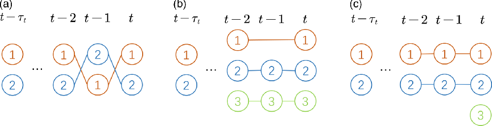
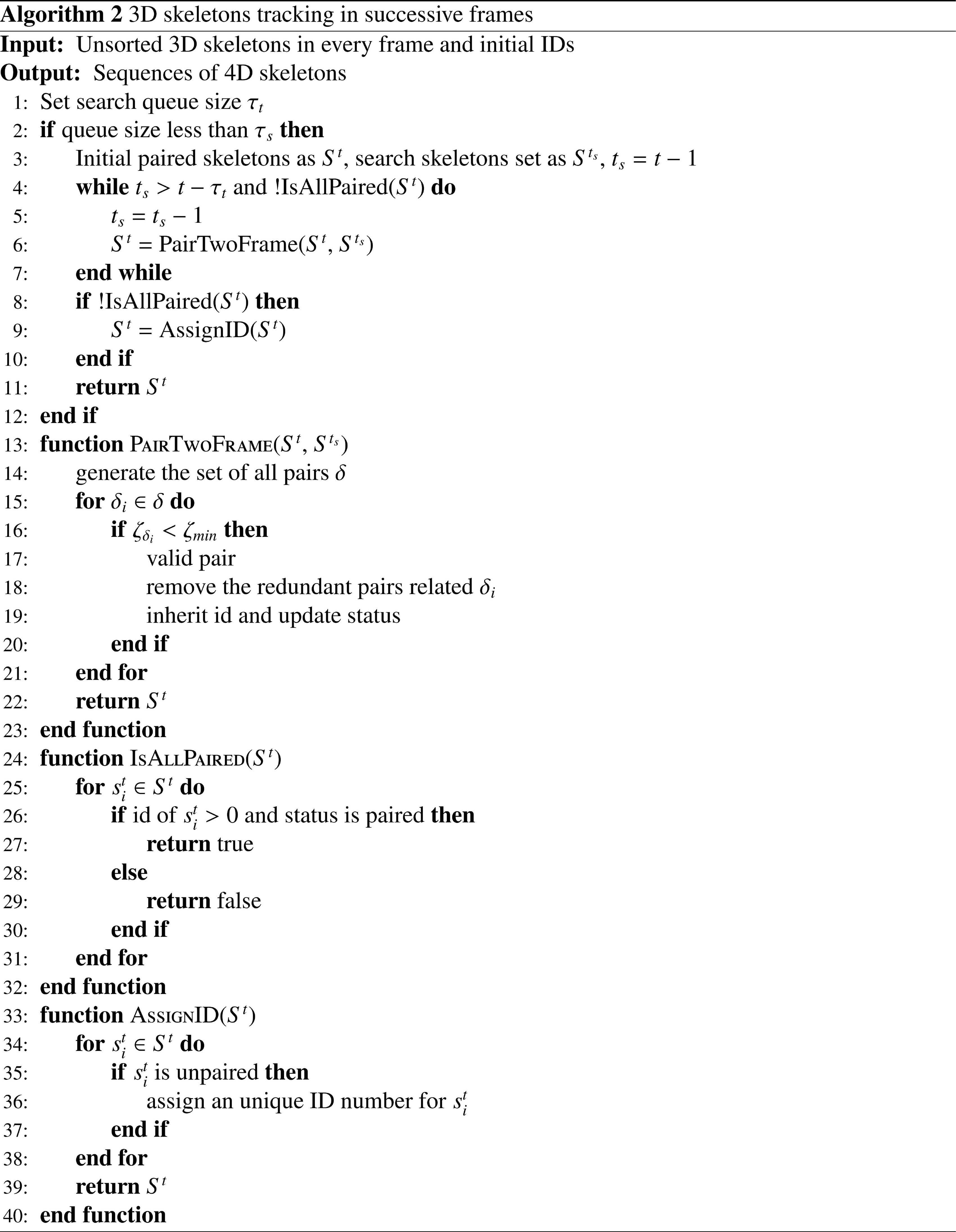
The 3D pose tracking stage inputs the unsorted multiple human 3D poses of each frame and outputs the 4D pose sequence with time information. The 3D skeletons belonging to the same person are associated in consecutive frames based on the greedy algorithm. As shown in Fig. 6, we consider three different association cases in consecutive frames. The corresponding confidence is calculated to connect the skeletons by the Euclidean distance between poses. The correspondence cost between skeletons can be calculated as follows:
 \begin{align} {\varsigma ^{3D}}(S_I^t,S_J^{{l_s}}) = \frac{{\sum\limits_{j = 1}^N {||} S_{Ij}^t - S_{Jj}^{{t_s}}|| \cdot \alpha _{Ij}^t\alpha _{Jj}^{{t_s}}}}{{\sum\limits_{j = 1}^N {\alpha _{Ij}^t\alpha _{Jj}^{{t_s}}} }} \end{align}
where ||·|| is the joints Euclidean distance of
 $s_{Ij}^t$
and
 $s_{Jj}^t$
, j = (1, 2, …, N)is the joint number, where N is total joints number in a skeleton, and t is current frame and t
s
is search frame.
Three tracking situations. In (a), it is an ordinary tracking situation, where the skeletons between different frames are connected by the corresponding confidence. In (b), the number of skeletons in the frame t is greater than the previous frame. For the unpaired skeleton 1, it will continue to search-forward and pair with the skeleton until l − τ t . t− In (c), the number of skeletons of the current frame t is also greater than the previous frame. After finishing the forward search process, there is still an unpaired skeleton (skeleton 3) in the current frame. The skeleton should be assigned a unique ID.

The tracking process is outlined in Algorithm 2. Define the current frame t as the paired frame and t
s
as the search frame. The search frame is initialized as t
s
= t−1 The correspondence of all paired skeletons in the current frame and the search frame is calculated from Eq. (9). For example, there are all four pairs for two persons, including two correct pairs and two mispairs. The purpose of tracking is to preserve the correct pairs and to remove the wrong ones. The ordered list is traversed by the increasing value of ζ, and the first valid association is found. An association is considered as valid if the correspondence score ζ is below the empirically estimated correspondence threshold ζ
min
= 0.2. The pose
 $s_i^t$
in the current frame will inherit the ID number of the pose
 $s_i^{{t_s}}$
in the search frame. At the same time, the redundant pairs related to it should be removed. If there are some unpaired skeletons in the current frame, it means that some new skeletons have appeared, or these skeletons have lost track due to association errors or occlusions during the pairing process. At this point, the search frame is set as t
s
= t−2. This algorithm will repeat the above pairing and updating process until t
s
= t – τ
t
, where τ
t
is the maximum search scope. If there is still an unpaired posture at this time, it can be considered that the posture newly appears, and a unique ID is assigned to the skeleton.
Our algorithm enables multihuman 3D poses to be tracked effectively even in the absence of some frames due to association errors or occlusion during the pairing process.
4. Robot Control Strategy
In the HRI process, the robot realizes interaction by tracking the task goals specified by the operators. However, the goals are potentially randomness and unreasonableness in the process of interaction. On one hand, operators cannot give precise task goals directly, and the ambiguous goals needs to be adjusted through constant feedback. On the other hand, the target point specified by the operator may exceed the effective working range of the robot, which causes the robot to move unsafely, even cause loss due to collision in the interactive process. To solve these problems, in this section, the task target generation and correction methods are proposed to ensure effective interaction for the robot based on boundary constraints according to the task in Fig. 1. Besides, for the requirements of multiple tasks, a robotic controller is designed to control the robot moving smoothly based on model predictivecontrol.
4.1. Task target generation and correction
In the interactive process, the robot always has a task goal
 $T_0^w$
in the workspace. Note that the interaction is achieved through the robot tracking goal
 $T_0^w$
. With the perception information and the designed tasks shown in Fig. 1, the generation methods of
 $T_0^w$
are presented to the corresponding interactivetasks.
In the multihuman–robot safety interaction, human joints are regarded as moving or stationary obstacles. For avoiding obstacles, a good method is the accumulation of attractive and repulsive forces between the obstacles and the end-effort of the robot [Reference Du, Shang, Cong, Zhang and Liu49]. In the interactive process, by sensing the distance between the end-effort and each joint of the human body in real time, the position of
 $T_0^w$
is calculated by the attraction and repulsion vectors. When the distance between the human joint and the robot is greater than the safety threshold
 ${\tau _d}$
, the robot will move to the original target
 $t_0^w$
, where
 $t_0^w$
is the translation vector of target
 $T_0^w$
. The target generates an attractive vector
 ${F_0}$
to the end-effort r
ee
of the robot.
 ${F_0}$
is expressed as follows:
 \begin{align}{F_0} = t_0^w - t_{{r_{ee}}}^w\end{align}
where
 $t_{{r_{ee}}}^w$
is the tool position of the robot in world coordinate w.
In contrast, if the distance
 $d_{h_j^i}^{{r_{ee}}}$
of the joint
 $h_j^i$
of person i to the end-effort r
ee
is less than
 ${\tau _d}$
, the repulsive force vector
 ${F_{h_j^i}}$
is generated as follows:
 \begin{align}{F_{h_j^i}} = \left\{ \begin{array}{cc}{\dfrac{{t_{{r_{ee}}}^w - t_{h_j^i}^w}}{{|t_{{r_{ee}}}^w - t_{h_j^i}^w|}}} &,\;\;\;\;\; if\;d_{h_j^i}^{{r_{ee}}} \lt {\tau _d} \\ 0 &,\;\;\;\;\; otherwise \end{array} \right.,\end{align}
where
 $t_{h_j^i}^w$
is the translation of the human joint in the world coordinate w.
Then, the synthetic force F
add
is divided into two items corresponding on the attractive vector
 ${F_0}$
and the repulsive force
 ${F_{h_j^i}}$
of all joints of each person. F
add
is defined as:
 \begin{align}{F_{add}} = {F_0} + \sum\limits_{i \in I\nabla } {\sum\limits_{j \in J\nabla } {{F_{h_j^i}}} } \end{align}
where
 $I\nabla $
and
 $J\nabla $
represent person set and joint set, respectively.
Next, the target
 $T_0^w$
is generated as follows:
 \begin{align}T_0^w = T_{{r_{ee}}}^g + \left[ {_0^{{F_{add}}}} \right][0\quad0\quad0\quad\delta ]\end{align}
where
 $\delta \in \left( {0,\infty } \right)$
is the distance coefficient to adjust linearly the synthetic force.
For the collaborative tasks, the position and orientation of the object are generated by detecting the AR markers pasted on its surface. In the beginning, a camera is fixed in the robot tool for detecting the AR marker. The position and orientation of the camera are equal to the transformation matrixof the end-effect of the robot with a constant translation error. The transformation matrix of thecamera in the world coordinate can be expressed as follows:
 \begin{align}T_c^w = T_{tool}^w + T_c^{tool} = \left[ {\begin{array}{*{20}{c@{\quad}c}}{R_{tool}^w + R_c^{tool}} & {}{t_{tool}^w + t_c^{tool}}\\0 & {}1\end{array}} \right]\end{align}
where
 $T_{tool}^w$
represents the transformation between the tool coordinate of the robot and the world coordinate,
 $T_c^{tool}$
represents the transformation between the camera and the tool coordinate of the robot.
The task target
 $T_0^w$
is the position of the object in the world coordinate, which is given by:
 \begin{align}T_0^w = T_c^wT_0^c\end{align}
where
 $T_0^c$
represents the transformation of the object o relative to the camera c.
In addition, the generated target goal
 $T_0^w$
should be constrained within the workspace of the robot to avoid singular state. The singular means that the joint angles cannot be solved through robotic inverse kinematics when the robot is fully deployed or multiaxis collinear. Supposed that the maximum theoretical workspace radius of the robot is R, then the practical workspace radius is restricted as
 ${R_{\it max}} = 0.9R$
in our experiment context. If the task point
 $T_{o}^{w}$
exceeds the workspace
 $W\left\{ {{R_{\it max}}} \right\}$
the position of
 $T_0^w$
will be replaced by limited boundary values. Similarly, the robot should be restricted outside the minimum work area
 $W\left\{ {{R_{\min }}} \right\}$
to avoid self-collision when moving, and the minimum work-area is set as
 ${R_{min}} = 0.2R$
.
4.2. Model predictive controller design
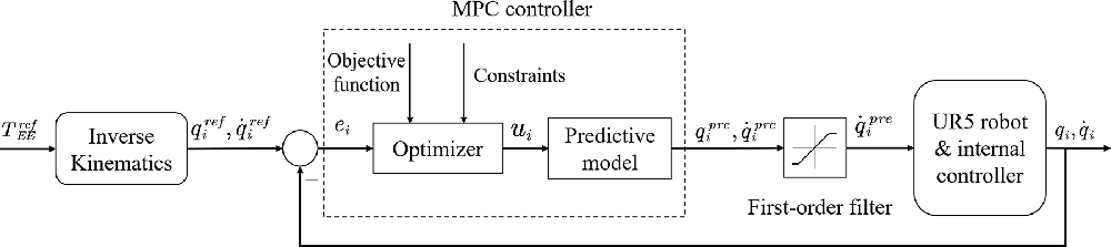
In the MHRI system, for robot control, the following aspects need to be considered: 1) The strong coupling between multijoint of the robot, linear controllers (such as PID) are difficult to achieve the expected control effect of the robot system with high coupling; 2) In the interactive process, there are some constraints (such as joint speed and acceleration) to meet the normal operation of the robot; 3) Multiple tasks have different requirements for the controller. For example, the robot needs to respond quickly to reduce trajectory tracking errors in collaborative tasks, whereas the smoothness of the trajectory is more important in human–robot safety. Aiming at the above problems, a low-level controller is designed to control the movement of the robot based on MPC. Firstly, the multijoint robot model can be regarded as a constrained multi-input multi-output (MIMO) control model. The advantage of the MPC is that it is a multivariable controller which takes into account all factors and outputs the controlled actions at the same time. Secondly, the MPC controller solves the actions by constructing the optimization problem. Some constraints can be added to the optimization problem to meet the expected results. In addition, the requirements of different HRI tasks can also be met by adjusting the corresponding penalty coefficients. The whole MPC control framework is shown in Fig. 7.
The MPC control system for UR5 manipulator. Given a target point
 $T_{EE}^{ref}$
, the state of each joint is solved by robotic inverse kinematics. The error e
i
between the current state and target state of each joint are taken as the inputs into the optimizer to calculate the control actions u
i
(i = 1, …,n). Input the action u
i
into predictive model to update the joint status, and control the movement of the robotic manipulator in real time after filter.

Define the robot joint as
 $q\in\mathbb{R}^{n}$
, where n represents the DOF of the robot. According to robotic kinematics, there is a nonlinear function between the end-effort T
EE
and the joint angle q.
 \begin{align}{T_{EE}} = {f_{kin}}\left( q \right)\end{align}
Let
 $\dot q$
refer to the joint velocities. The state x of the control system can be denoted as
 ${[q,\dot q]^T}$
. Let the control action
 $u = \ddot q$
. The dynamic system is given as follows:
 \begin{align}\begin{array}{l}\dot x = f(x,u) = \left[ {\begin{array}{*{20}{c@{\quad}c}}0 {}& 1\\0 {}& 0\end{array}} \right]x + \left[ {\begin{array}{*{20}{c}}0\\1\end{array}} \right]u\\y = \left[ {\begin{array}{*{20}{c}}1\quad {}0\end{array}} \right]x\end{array}\end{align}
The discrete equation of the continuous state system with a sampling time of t s is expressed asfollows:
 \begin{align}{x_{k + 1}} = {x_k} + \left[ {\begin{array}{*{20}{c}}{\dot{q}{t_s} + \dfrac{1}{2}u{t_s}}\\{u{t_s}}\end{array}} \right]\end{align}
The purpose of the controller is to calculate the trajectory of the robot from the starting pose q 0 to the desired pose T goal . The problem of nonlinear model predictive control for trajectory planning can be expressed as follows:
 \begin{align}objective:\min {l_N}({x_N}) & + \sum\limits_{k = 0}^{N - 1} {{l_k}({x_k},{u_k})} \nonumber \\subject\;to\,&:\,{x_0} = {x_{start}},{f_{kin}}({q_N}) = {T_{goal}}\\ & {x_{k + 1}} = {f_k}({x_k},{u_k}),k \in {N_{[0,N - 1]}}\nonumber\\ & {u_k} \in {U_k},k \in {N_{[0,N - 1]}}\nonumber\\ & {x_k} \in {X_k},k \in {N_{[0,N]}}\nonumber \end{align}
where X
k
and U
k
are assumed to be closed and compact convex set projections. In this study, X
k
and U
k
correspond to the state and joint acceleration constraint, respectively. Here,
 ${l_k}({x_k},{u_k}):{\textbf{R} ^{{n_x} \times {n_u}}} \to \textbf{R} $
refers to the stage costs at the k-th instant, which can be defined as:
 ${l_k}({x_k},{u_k}) = {({x_k} - {x_{ref}})^T}{Q_k}({x_k} - {x_{ref}}) + {({u_k} - {u_{ref}})^T}{R_k}({u_k} - {u_{ref}})$
and the terminal cost
 ${l_N}({u_N}):{\textbf{R}^{{n_x}}} \to \textbf{R} $
is defined as:
 ${l_N}({x_k}) = {({x_N} - {x_{ref}})^T}{Q_N}({x_N} - {x_{ref}}),$
where R
K
, Q
K
and Q
N
are the penalty coefficients, X
K
and U
K
are the k-th system state and joint acceleration, respectively, x
ref
and u
ref
are reference value of system state and joint acceleration, x
n
is terminal state.
The objective function is minimized by the PANOC algorithm [Reference Sopasakis, Fresk and Patrinos50] which adopts the limited-memory BFGS to speed up convergence. PANOC is a first-order matrix-free solver for nonconvex optimization problems with favorable convergence properties. It can easily deal with hard constraints that have a feasibility set that permits a computationally simple projection operation. The main feature of PANOC algorithm is summarized here. Let
 $o(z):\mathbb{R}^{n_{z}}\rightarrow\mathbb{R}$
be a function that is
 ${C_{{L_l}}}$
. Let Z denote the feasibility set of z. One can define a projected gradient step as:
 \begin{align}{z^{v + 1}} = {\varPi_z}({z^v} - \gamma {\nabla _o}({z^v}))\end{align}
where
 $\varPi$
denotes a projection operation to the feasible set Z and (20) always leads to a decrease in cost function if
 $\gamma \lt 1/{L_l}$
A series of iterates
 ${z^v},{z^{v + 1}}, \ldots $
are used to implement a limited-memory quasi-Newton method.
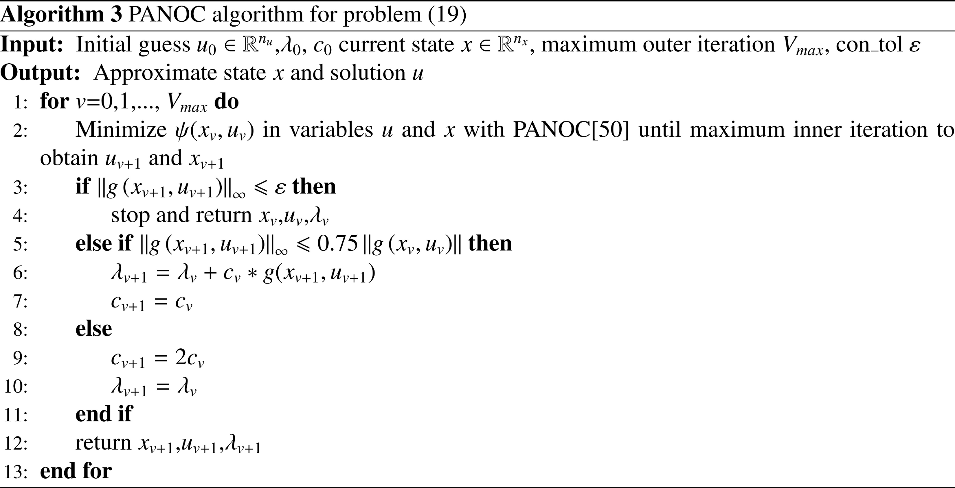
For the problem (19), such constraints are typically solved using quadratic penalty method. For the quadratic penalty method, the square sum is multiplied by a factor and added to the original cost function. This factor is increased sequentially in an outer iteration step to satisfies the constraints more closely. Considering that the high factor will cause ill-conditioning and convergence issues in the penalty method. We try to satisfy constraints more accurately by increasing the factor to a very high value with the ALM [Reference Bertsekas51]. Let
 $x = [{x_1}\,{x_2}\,{x_3} \ldots {x_N}]$
and
 $u = [{u_1}\,{u_2}\,{u_3} \ldots {u_{N - 1}}]$
, the quality constraints as the residual from (19b) and (19c) as g (x, u). The total objective function from (19a) be defined as:
 \begin{align}L(x,u) = {l_N}({x_N}) + \sum^{N - 1}_{k = 0} {{l_k}({x_k},{u_k})} \end{align}
The augmented Lagrangian formulation for problem (21) can be defined as follows:
 \begin{align}\psi (x,u,\lambda ,c) = L + {\lambda ^T}g(x,u) + \frac{1}{2}\mu ||g(x,u)|{|^2}\end{align}
where λ,
 $\mu$
are the penalty coefficients. The algorithm for minimizing the augmented Lagrangian is presented in Algorithm 3.
Due to the presence of noise, the trajectory of the robot may fluctuate in actual applications. We use the first-order filter to filter the output value of the system to make the trajectory smoother for the robot. The first-order filter can be expressed as:
 \begin{align}{y_f}(t) = \alpha .{y_f}(t - 1) + (1 - \alpha )\cdot{y_m}(t)\end{align}
where y
f
, y
m
are the filtered value and the measured value, respectively;
 $\alpha = {e^{ - {T_s}/\tau }}$
, where T
s
is the sampling time and τ is time constant.
5. Experiment and Result
In the following subsections, the multihuman pose perception and the robot trajectory tracking are described, then the presentation and the discussion of the obtained results are reported. At the end, the effectiveness and feasibility of the proposed MHRI system has been demonstrated through multihuman robot safety and multihuman robot collaboration.
5.1. Experiments of multihuman 3D poses estimation
5.1.1. Datasets and evaluation metrics
COCO. [Reference Lin, Maire, Belongie, Hays, Perona, Ramanan and Zitnick52] A large-scale object detection dataset, which contains more than 200,000 images and 250,000 person instances labeled with keypoints. Annotations on train and val (with over 150,000 people and 1.7 million labeled keypoints) are publicly available. In experiments, the pixel locations of multihuman 2D keypoints are regressed on the dataset.
CMU Panoptic. [Reference Joo, Simon, Li, Liu, Tan, Gui and Sheikh48] A large-scale dataset contains various indoor social activities (playing an instrument, dancing, etc.), which are collected by multiple cameras. Mutual occlusion between individuals and truncation makes it challenging to recover 3D poses. Similarly, the 3D position of human joints are regressed on this dataset in our experiment.
MPJPE. Mean per-joint position error (MPJPE) is a common metric that corresponds to the mean Euclidean distance between ground truth and prediction for all joints of total people.
 \begin{align}MPJPE = \frac{1}{N}\sum\limits_{i = 1}^N {||{J_i} - J_i^*|{|_2}} .\end{align}
where N is the number of joints, J
i
and
 $J_i^{\ast}$
are the estimated position and the ground truth position of the i-th joint, respectively.
5.1.2. Training details
This study implements the proposed network scheme by the pytorch 1.6.0 framework at the Ubuntu 20.04 Operating System. The CPU is i9-9700 with the running memory of 32G, and the GPUs are three NVIDIA TITAN XPs. According to the training process in ref. [Reference Zhen, Fang, Sun, Liu, Jiang, Bao and Zhou27], the optimizer is the Adam optimization, the parameters
 $\beta_{1}$
and
 $\beta_{2}$
are 0.9 and 0.999, respectively. The learning rate is 0.0002 and the batch size is 32 for a total of 20 epochs on mixed datasets of COCO and CMU Panoptic. Images are resized to a fixed size of 455 × 256 as the input of the network, and 200K images from different sequences are selected as our training set, all images from four activities (Haggling, Sports, Ultimatum, Pizza) in two cameras (16 and 30) as our test set. Since the COCO dataset lacks 3D pose annotations, the weights of 3D losses are set to zero when the COCO data is fed.
5.1.3. Results of multihuman 3D pose estimation
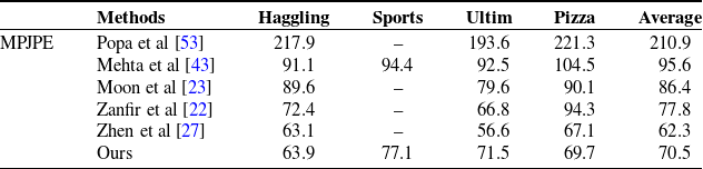
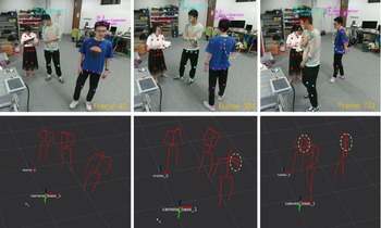
We use general evaluation index to carry out quantitative estimation of the proposed scheme, and compare it with existing methods. Table I provides the results over the recent state of the art methods on the CMU Panoptic dataset. It indicates that our model outperforms previous methods excepting [Reference Zhen, Fang, Sun, Liu, Jiang, Bao and Zhou27]. Our average error is only 8 mm away from the state-of-the-art (SOTA) method [Reference Zhen, Fang, Sun, Liu, Jiang, Bao and Zhou27]. In particular, the results on Haggling and Pizza scenarios are roughly equal to it. As these sequences share no similarity with the training set, the result shows the generalization ability of our model. The examples of multihuman 3D human pose estimation on our MHRI context are shown in Fig. 10. Our method can estimate the whole 3D pose for each person even in case of people overlap (2nd row).
Compared the results of human 3D poses estimation with SOTA works in CMU datasets. Haggling, Sports, Ultim, and Pizza represent different scene video sequences in this dataset.

5.2. Multihuman action recognition
Theoutput 2D poses are employed to recognize the action context of each people in our MHRI system. Before training, we create the action dataset by using the outputs of the 2D pose network branch. Some images of the dataset are shown in Fig. 8.
Example of action dataset in HRI scene.

The action recognizer is a classification model. In the training process, we adopt Adagrad as the optimizer with 3e-3 learning rate. The batch size is 512, and the loss function is CrossEntropy. We train the classification model for 100 epochs on the action dataset as the final model. The input of the model is the 2D joint pixel position, and the output is the corresponding action label.
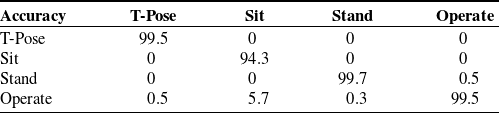
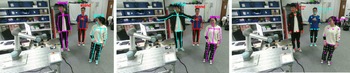
Table II shows that the classification model has high accuracy in predicting the actions of multiple people. An example of multiple people recognition process in our MHRI context is shown in Fig. 9. The person with T-pose action is regarded as the operator(red), and the other are nonoperators. Note that only one operator is set at this time.
Action recognition quality analysis. The number represents the corresponding accuracy. Accuracy = the sample number of predict right/total sample number.

The recognition process of operators and nonoperators.

5.3 Multihuman 3D pose tracking
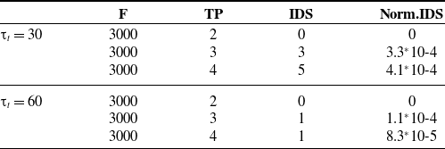
A common metric [Reference Voigtlaender, Krause, Osep, Luiten, Sekar, Geiger and Leibe54] in multiobject tracking, which counts the identity changes of the tracked objects. These scores are shown in Table III. The video sequences with varying numbers of people are collected firstly, which include walking, interacting, occlusion, etc. Each sequence includes approximately 3k images. The tracking result is verified in these video sequences.
Multihuman 3D poses tracking quality analysis. The number of frames(F), tracked people (TP), ID switches (IDS), and ID switches after adjusting for number of frames and number of tracked people (Norm. IDS) in each sequence (Norm. IDS = IDS/TP/F).

Table III shows that the pose tracking algorithm has good robustness. In the case of small number of people, the skeletons can be tracked correctly. However, the tracking accuracy will decrease with the increase of the number of people. The reason is that the occlusion between the persons are inevitable, which will cause the loss of the occluded human posture when the number of people increases. A good solution is to increase the scope
 ${\tau _l}$
of the search frame, but it also increases the calculation time (the best time complexity is O(1), the worst case is O(
 ${\tau _l}$
) according to Fig. 6). Table III shows the results of
 ${\tau _l}$
= 30 and
 ${\tau _l}$
= 60, respectively.
Figure 10 shows the estimation, recognition, and tracking results of the multihuman pose. In the process of human pose estimation, multiple persons are labeled by various colors (as shown in the top row of Fig. 10). Furthermore, the operator is selected in recognition stage according to the task requirements. In the tracking process, we select three different images to show the multihuman 3D poses tracking performance. The multihuman 3D pose estimation, recognition, and tracking video is presented in: https://youtu.be/wvGmZx1Jghc.
Qualitative analysis of multihuman 3D pose perception. There are three example images. For each case, the top row shows the input image, and the bottom row shows the 3D pose estimation results in RVIZ. The action recognition and tracking results are shown in the image by different colors. The orange circles highlight the occluded limbs in localization of human bodies.

5.4. Real-time performance of the network analysis
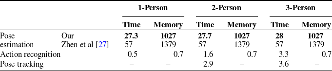
We verify the time cost for each stage in MHRI scene, including the pose estimation, recognition, and tracking. A bottom–up strategy and a lightweight backbone are employed to reduce the inference time for pose estimation. For pose recognition, the inference time and GPU memory can be ignored because the model is tiny. For pose tracking, only the Euclidean distance of the paired poses is calculated, the time complexity depends on the number of paired poses.
Table IV shows that the estimation stage takes about 28 ms to predict the multihuman 3D pose through the network, and the memory size is a constant number because of a fixed size of input images. In particular, we compare the result with the SOTA method [Reference Zhen, Fang, Sun, Liu, Jiang, Bao and Zhou27], and our network inference time is only half of it. In the recognition and tracking stages, the average calculation cost (2.5 ms and 3.3 ms) can be ignored. However, the corresponding cost time will also increase with the increase of the number of people. Nevertheless, it does not affect the overall real-time performance. Note that the search scope
 ${\tau _l}$
is set to 60 at this time.
Run time and memory calculation. The units of time and memory are ms and M, respectively. Pose estimation and recognition stages run through the GPU, and the consumption time represents the inference cost of a image. The memory is the size of the GPU memory occupied in the inference process. Pose tracking stage runs on the CPU and does not consume GPU memory resources.

5.5. The experiment of the robot target tracking
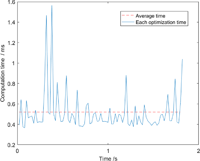
The MPC controller is validated on a UR5 robot manipulator with 6 DOF. In the experiment, the performance of the robot is verified by tracking the human wrist joint trajectory through adjusting the corresponding weight parameters. The MPC sampling time is set to 0.16 s with a horizon of four steps, and the controller runs at a rate of 50 Hz. The maximum values of joint speed v max and acceleration a max are limited to 1.5 rad/s and 3.0 rad/s2 , respectively. The joint states (joint angle and velocities) are read from the robot once each 20 ms, which is taken as the starting point for the MPC solver to compute the control action. Then, the joint states are updated to the actual robot model. In this study, the computation time required with the PANOC solver is about 0.52 ms, as shown in Fig. 11. The penalty coefficients are given by Q k = Q N = [10.0, 4.0], and R k = 2.0 to simultaneously meet avoidance and collaboration.
The MPC controller time cost. The blue line represents the time cost of each optimization stage, and the red line represents the average time cost.

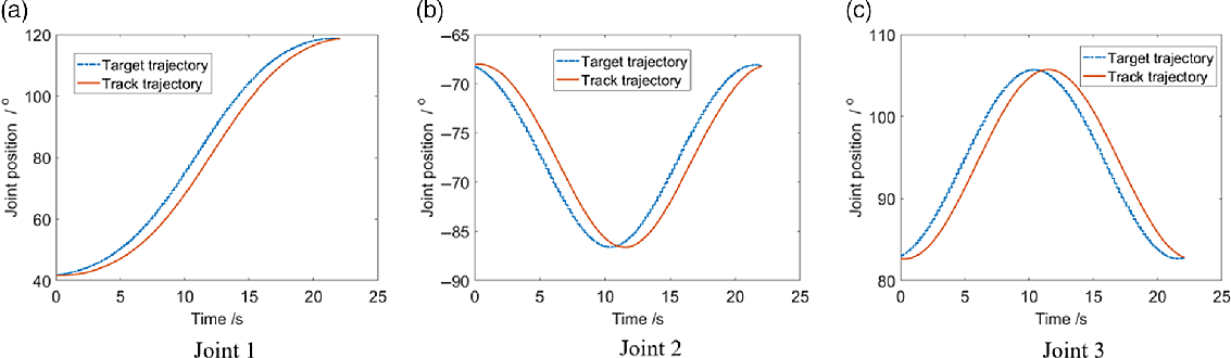
In the tracking experiment, the robot moves from the start point to the reference goal. As shown in Fig. 12, it could be seen that the tracking trajectory is converging to the reference goal continuously, which verifies the validity of proposed method. The tracking error is calculated by the joint errors and the average tracking error is about 3 mm with terminal constraint. Experiment shows that the controller has a good performance even if taking into account the inherent time lag (prediction) of model predictive control, and the tracking error is within the allowable range of the MHRI system requirement.
Target tracking diagram of the MPC controller. The blue line represents the target trajectory, and the orange line represents the track trajectory. The three figures show the track trajectories of the robot joints 1–3, respectively.

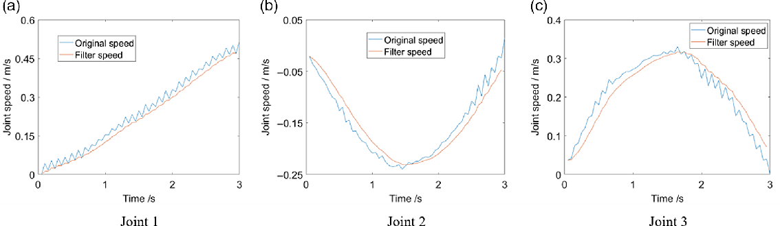
At the end, the first-order filter is employed to filter out the noise to make the robot move smoothly for better interaction. The parameters set as T s = 1 and τ = 3 at this time. As shown in Fig. 13, the robot joints have irregular rectangular tooth waveform (blue line) because there is noise interference when the hardware collects information. It will cause the robot to jitter during operation. After filtering, the joint speed of the robot is smoother for improving the human interaction experience, as shown by the red line in Fig. 13. Note that the parameter α in Eq.23 cannot be set to large because it will increase the delay time of the robot.
Schematic diagram of the robot joint filtering. The blue line represents the original speed, and the orange line is filter speed.

5.6. Human–robot interactive experiment
5.6.1. System setting
To illustrate the effectiveness of the proposed MHRI system, in this study, two high-definition (HD) cameras sensors are required, one of which is employed for human body capture and the other for object detection. The image resolution of the HD camera is 1920 × 1080. Both cameras are connected to the host machine through the USB3.0 interface. Due to different OS requirements of deep learning and the robot driver on the system, two computers are required. A desktop computer configured with i7-8700X and Nvidia Titan XP cards is the host PC for multihuman 2D/3D pose estimation, recognition, and tracking, and a laptop as the slave controls the movement of the robot. The master–slave machine communicates with each other by publishing or receiving ROS topic messages based on TCP/IP.
5.6.2. Evaluation metrics
For our MHRI system, the performances of system safety and quantitative measures are considered, such as team performance. In most cases, the metrics are independent of the content of the interaction scenario. The metrics currently included in the MHRI system consist of the proposed safety rate, interference delay, and other related metrics from ref. [Reference Voigtlaender, Krause, Osep, Luiten, Sekar, Geiger and Leibe54]. These metrics are described as below:
-
(1) Safety rate: the percentage of trajectories that the robot can safely avoid human interference.
-
(2) Team efficiency: the percentage of tasks completed by design autonomy.
-
(3) Team effectiveness: the time required for the human–robot team to complete the tasks successfully.
-
(4) Human idle time (H-IDLE) and robot idle time (R-IDLE): the percentage of the total time that agents (human or robot) are inactive. The metrics reflect the performances of team coordination and agent utilization.
-
(5) Concurrent activity (C-ACT): the percentage of the total time of both agents are active simultaneously. This metric can be seen as a sign of team synchronization and balanced work.
-
(6) Interference delay (I-DEL): the percentage of the total time that the human operators interfere the movement of the robot during the interaction. It is included in the C-ACT.
The above metrics evaluate the process of MHRI through generalized measurement parameters without considering the specific HRI tasks and scenarios. Therefore, these metrics can be employed to evaluate the MHRI system and interactive tasks designed.
5.6.3. Multihuman–robot safety experiment
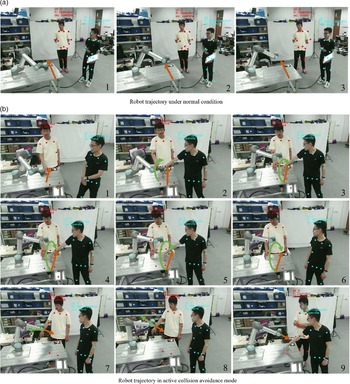
In the multihuman–robot safety, the robot can avoid the operators actively when they enter the workspace of the robot in the interaction process. The origin trajectory of the robot is shown in Fig. 14(a). When any person is close to the robot working area, the original trajectory of the robot is blocked by human joint, as shown in Fig. 14(b). The system readjusts the trajectory of the robot through the artificial potential field, and the robot reaches the target position without conflict with the human body. In the experiment of the multihuman robot safety, the safety efficiency is measured by the ratio between the number of obstacle avoidance paths and the total running trajectories of the robot. The trials of static and dynamic obstacles are considered in the MHRI process. For the former, the human joint is placed in the middle of the running path of the robot. We record 50 robot trajectories and observe that the number of successful obstacles avoidance paths is 48, and the safety efficiency, in this case, is 96%. For the latter, the human joints are dynamic moving when the robot runs. In this case, 40 robot trajectories are recorded and the number of successful obstacles avoidance paths is 36, and the safety efficiency is 90%. Compared with the former, the randomness of the dynamic trial is stronger and the safety efficiency is lower than the static trial. Experiments show that our MHRI system has good safety performance. The MHRI safety video is presented in https://youtu.be/zmodf45ajHg.
Multihuman robot active collision avoidance.

5.6.4. Multihuman–robot collaboration experiment
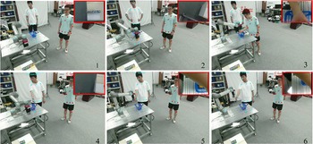
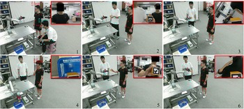
As mentioned in Section 2, two situations exist for multihuman–robot collaboration assembly: both the operators and nonoperators or multiple operators. In the former, the operator and robot cooperate to complete the specified task, and the nonoperator is regarded as an obstacle to keep safe with the robot. As shown in Fig. 15, an operator (red) and a nonoperator (green) exist. The robot grabs the block from the table and returns to the workbench, waiting for the operator to come and fetch it, whereas the nonoperator is regarded as obstacles. The perspective of the end-effort of the robot is shown in the red box. In the latter, multiple operators and the robot work together to complete the same task, further improving the efficiency of collaboration. As shown in Fig. 16, there are two operators. The operators hold the marked object, and the robot will actively grab the object and put it in the basket. The perspective of the robot end-effort is also shown in the red box. In the collaboration process, the end-effort of the robot first reaches an approximate position with respect to the human body root joint. Then, the AR-Marker pasted on the object is set as the target position for grabbing it, which outputs the 6D pose of the block through the camera fixed in the end effort of the robot. The MHRI collaboration video is presented in https://youtu.be/55gDJ3cyfNs.
Single human–robot collaboration assemble.

Multihuman–robot collaboration assembly.

To ensure the correctness of the experimental results, we define the same task: block transportation. Three trials correspond to the three situations in Fig. 1. Table V lists the metrics gathered from each trial of the transport task. For all experiments, effectiveness is always 1.0 because the study can always be completed, but it requires different time costs which are 208 s, 258 s, and 210 s, respectively.
Assembly Task Study Metrics

For the first case, the robot completes its work autonomously, but it will be interfered with by humans. In this process, the human agent has two states: active (I-DEL time is 38%) or inactive (H-IDLE time is 62%). The robot does not need to wait for the operator to release the task point and keeps working (R-IDLE time is 0). Hence, the autonomous case has the best efficiency with a study completion time of 208 s. Besides, the concurrent activity time (C-ACT time is 38%) equals the interference delay because obstacle avoidance means that the robot and operators are active in the interaction process.
For the second case, the robot collaborates with the operator while keeping safe with the nonoperator. The time cost is increased by the R-IDLE time (R-IDLE time is 15%) because the robot needs to wait until the operator publishes the task point. In this experiment, the H-IDLE and C-ACT times are accumulated by the activity time of the operator and the nonoperator. The I-DEL time is only recorded by the activity time of the non-operator. This case has an impact on the team effectiveness, but it can adapt to more flexible environmental changes.
For the third case, all humans are the operators, so the I-DEL time is 0. The robot only waits for different operators to publish the task points, and the R-IDLE will increase because there is a delay time between task points. The H-IDLE time is decreased because of the increase of human tasks. The transport efficiency is better than that in Case 2. The experiment shows that multiple operators–robot interaction can improve the work efficiency compared to the single operator–robot interaction.
6. Conclusion
In this study, a MHRI system is designed with human–robot motion capture and the robot flexible control strategy. In human–robot motion capture, the pose of the robot is estimated by the robot kinematics and robot hand-eye calibration. For multihuman 3D pose estimation, a real-time 3D pose estimator based on CNN is presented to perceive the 3D poses of multiple persons in the interactive process. At first, the estimator takes the lightweight backbone to extract joints features and reduce inference time. Then, a priority–redundancy association algorithm is proposed to assign 3D joints for each individual and solve the occlusion problem among multiple persons. Considering the conditions of nontask demand and interfering personnel in the interactive process, an operator and nonoperator recognition algorithm with action recognition and skeleton tracking is proposed to ensure the stability of the multihuman interactive process. For the robot control strategy, corresponding task target generation and correction methods are designed for different interactive modes. Besides, a low-level MPC controller is developed to generate the motion trajectory according to the target goal. HRI is realized through the robot tracking the trajectory. Experimental results are included to show the stability and robustness of multihuman 3D pose estimation, recognition and tracking, the smoothness of target tracking of the robot, the feasibility, and effectiveness of the MHRI system in different modes. This innovation expands the research of multihuman robot interactive control in complex environments and provides a reference for further improving industrial manufacturing. In future work, we will conduct research on human body information perception to improve the accuracy of human body posture estimation.
Conflicts of Interest
None.
Ethical Considerations
None.
Authors’ Contributions
None.
Acknowledgments
This study was supported by National Key R&D Program of China (2018YFB1308400) and Natural Science Foundation of Zhejiang province (LY21F030018).