1. Introduction
Nowadays, robotic manipulators play crucial roles in the industry from the pick-and-place operation in food companies to the spot welding and color spray in car manufacturers. Accuracy, speed, and load capacity are important factors that lead engineers and researchers to search for innovative light and stiff architectures. Serial robots with a large workspace and simple design have been widely known as reliable manipulators in the industry. However, due to higher stiffness, speed, and accuracy, parallel robots have attracted the attention of researchers and engineers in the last two decades, yet, their complex architecture calls for more efforts to further promote the practical applications of them [Reference Sun, Lian, Song and Feng1].
Generally, one of the important steps in the embodiment design stage of robotic manipulators is the dynamic analysis, which can be inverse or forward. In the former analysis, the moving platform (MP) trajectory is known, and commonly, the input torques and constraint wrenches (forces and moments) are demanded; while in the latter, it is the other way around, that is, the input torques are known and the trajectory of the MP and the constraint wrenches at the joints are asked. When the simultaneous computation of input torques and constraint wrenches is important, it is sometimes referred to as constraint wrench or force analysis. As manipulators are usually designed for a specific task in which the MP should follow a certain trajectory, the constraint wrench analysis seems more informative and important. Therefore, the current study aims at shedding more light on this subject in robotic systems such as manipulators.
In the last three decades, many researchers have targeted the dynamic modeling of robotic manipulators by resorting to energy-based methods [Reference Miller2–Reference Enferadi and Jafari8] or the Newton–Euler formulation [Reference Kingsley and Poursina9–Reference Nabavi, Akbarzadeh and Enferadi12]. Although the energy-based methods, such as Lagrange equations or the principle of virtual work, are easier to implement, they are mostly involved with intensive mathematical derivations and manipulations. Moreover, some of the variables, such as Lagrange multipliers or generalized speeds, which can be defined entirely mathematical, cannot deliver physically meaningful interpretations in the complicated mechanisms. On the opposite side, the Newton–Euler formulation is engaged with physical variables, such as velocity and acceleration of links or constraint forces and moments. Generally, the Newton–Euler method is considered more efficient for the generation of equations [Reference Koplik and Leu13]. However, in the Newton–Euler method, the correct equations of motion are derived only if the dynamic behavior of each component and its interaction with other components of the system are understood properly. As a result, constraint forces and moments at joints can be naturally obtained, in addition to the input torques/forces. Therefore, whenever the input–output relation is only demanded, the energy-based methods look more efficient [Reference Mazare, Taghizadeh and Najafi7, Reference Liping, Huayang and Liwen14–Reference Mo, Shao, Guan, Xie and Tang19]. Mo et al. [Reference Mo, Shao, Guan, Xie and Tang19] conducted a dynamic analysis on the X4 parallel robot by means of the principle of virtual work. The authors, then, defined a dynamic performance index based on the obtained input–output dynamic equations. In some cases, the energy-based methods have been used to compute the constraint forces and moments by introducing physically meaningful kinematic constraint equations and the corresponding Lagrange multipliers [Reference Pappalardo and Guida20–Reference Arian, Danaei and Tale Masouleh23]. Cibicik et al. [Reference Cibicik and Egeland24] introduced a systematic methodology based on the Kane’s equations of motion to determine the reaction forces of a knuckle boom crane. However, as it was mentioned earlier, if the constraint forces and moments are desired, researchers have often relied on the Newton–Euler formulation [Reference Kingsley and Poursina9–Reference Li and Xu11, Reference Bi and Kang25–Reference Roth28]. This point is explicitly supported by Gan et al. [Reference Gan, Dai, Dias and Seneviratne26] where a metamorphic parallel robot was studied.
Screw theory is commonly considered as a strong mathematical tool in kinematic and dynamic analysis of spatial manipulators, especially with parallel architecture. In this theory, a line in the space is defined by a six-dimensional array of Plücker coordinates [Reference Pottmann and Wallner29], of which only four are independent. In the so-called ray coordinates, the first three components denote a unit vector parallel to the line, and the rest are the three components of moment vector of line with respect to an origin. However, in the axis coordinate, this order is vice versa [Reference Dai and Sun30]. A screw is then represented as a line array with the fifth independent parameter, a pitch. A twist which is composed of a point velocity and an angular velocity vector, or a wrench which is composed of resultant force and moment vectors are derived upon multiplication of the screw array by an amplitude A, as a sixth parameter. Amplitude A can have units of angular velocity, rad/sec, or of force, N, which results in twist or wrench, respectively. Combined with the principle of virtual work, researchers have shown the merit of screw theory in dynamic analysis of spatial manipulators [Reference Geike and McPhee31–Reference Chai, Wang, Xu and Ye35]. Angeles and Lee [Reference Angeles and Lee36] have incorporated the screw theory notations and the natural orthogonal complement method in the Newton–Euler formulation for the dynamic analysis of serial robots. Later, Angeles extended the methodology for parallel counterparts as well [Reference Angeles37]. However, the proposed methodology was mainly tailored to calculate the actuator torques/forces via the input–output Eq. (38). Although in the most dynamic analysis, only the input torques or the input–output relations are demanded, the constraint wrenches play a critical role in understanding the dynamic behavior of a mechanism in terms of the transmission of forces and moments between components. Moreover, in the stress analysis of flexible parts, or the friction force computation at joints, the calculation of constraint wrenches is inevitable. Founded on the kinematic constraint equations, which were defined in [Reference Angeles and Lee36, Reference Angeles37], Taghvaeipour et al. [Reference Taghvaeipour, Angeles and Lessard39] proposed a methodology to obtain the constraint and applied forces/moments in the inverse dynamic modeling of multibody systems, simultaneously. In this method, the authors introduced the constraint transformation matrix (CTM), which was extracted from the kinematic constraint relations exerted by kinematic pairs on the connected rigid links. As the composition of CTM relies on the joints’ kinematic constraints, the foregoing methodology is referred to as the joint-based constraint wrench analysis. Later, Ghaedrahmati et al. [Reference Ghaedrahmati, Raoofian, Kamali and Taghvaeipour40] modified the foregoing methodology by introducing a new CTM, which was simply obtained by applying the wrench transfer formula [Reference Angeles37] on each rigid link. Therefore, as opposed to the previous method, this approach is referred to as the link-based constraint wrench analysis.
The results revealed that both approaches were able to determine the essential dynamics variables such as the actuator torques and the magnitude of constraint force/moment vectors, as it was reported in [Reference Taghvaeipour, Angeles and Lessard39] and [Reference Ghaedrahmati, Raoofian, Kamali and Taghvaeipour40], respectively. However, as the methods form the CTM differently, the results can be expected to be different, and they should be analyzed carefully. In fact, it was learnt that, due to the mathematical manipulations in constraints derivations, the joint-based approach cannot report the constraint force and moment components in meaningful directions with respect to a specific coordinate frame. Moreover, in both methodologies, the obtained CTMs are not full-rank; in other words, in the aforementioned constraint wrench analysis, kinematic constraint equations between rigid links are considered redundantly. Therefore, the first target of the current study is to shed more lights on the differences between the two methodologies and the obtained results, which will be clearly delivered via two case studies. Next, the remained part of the paper is devoted to find an answer for this question that “Are there any performance indices that can be extracted from the constraint matrix of a multibody system?” The rank deficiency of the CTMs which are derived from the aforementioned methodologies seems a barrier to this goal. Thus, in order to derive a full-rank CTM, the joint-based method will be modified by resorting to the definition of reciprocal screws. Based on the obtained CTM, finally, the constraint forces and moments distribution indices are introduced, which will be examined on the case studies as well.
The remainder of this paper is formed as follows. Section 2 briefly describes the basics of the constraint wrench analysis. Section 3 elaborates the joint-based method. Section 4 introduces the modified joint-based method, and section 5 explains the link-based counterpart. Section 6 introduces the constraint forces and moments distribution indices. In section 7, the three methodologies are applied on a spherical four-bar linkage and a Delta parallel manipulator, and discussion is made on the obtained results. Conclusions are presented in section 8.
2. Constraint wrench analysis
Complete design and analysis of a robot’s structure need the calculation of constraint wrenches which are produced at joints during a given operation. Using the Newton–Euler method and based on the screw theory notation, the equations of motion of the
 ${i^{th}}$
link can be represented as [Reference Angeles37]
 \begin{equation}{{\bf{M}}_i} \dot{\textbf{t}}_{i} + {{\bf{W}}_i}{{\bf{M}}_i}{{\bf{t}}_i} = {}_{}^A{{\bf{w}}_i} + {}_{}^G{{\bf{w}}_i} + {}_{}^C{{\bf{w}}_i}\end{equation}
where
 ${{\bf{t}}_i}$
is the six-dimensional twist array of the
 $i$
th link containing the angular velocity,
 $\;{{\unicode[Times]{x1D6DA} }_i}$
, and the velocity of its center of mass,
 ${{\bf{v}}_i}$
, namely,
 \begin{equation}{{\bf{t}}_i} = {\left[ {\begin{array}{{c}}{{{\unicode[Times]{x1D6DA} }_i}}\\{{{\bf{v}}_i}}\end{array}} \right]_{6 \times 1}}\end{equation}
Also,
 ${{\bf{M}}_i}$
and
 ${{\bf{W}}_i}$
are the inertia and angular velocity tensors, respectively, which are defined as follows:
 \begin{align}{{\bf{M}}_i} = {\left[ {\begin{array}{{c@{\quad}c}}{{{\bf{I}}_i}} & {{{\bf{O}}_{3 \times 3}}}\\{{{\bf{O}}_{3 \times 3}}} & {{m_i}{{\bf 1}_{3 \times 3}}}\end{array}} \right]_{6 \times 6}},{\rm{\;\;}}{{\bf{W}}_i} = {\left[ {\begin{array}{{c@{\quad}c}}{{{\boldsymbol{\Omega }}_i}} & {{{\bf{O}}_{3 \times 3}}}\\{{{\bf{O}}_{3 \times 3}}} & {{{\bf{O}}_{3 \times 3}}}\end{array}} \right]_{6 \times 6}}\end{align}
in which
 ${{\boldsymbol{\Omega }}_i}$
is the Cross Product Matrix (CPM) of the angular velocity vector,
 ${{\bf{I}}_i}$
is the inertia matrix of the rigid link i with respect to its center of mass and
 ${\bf{O}}$
is the
 $3 \times 3$
zero matrix. Also, the mass is denoted by
 ${m_i}$
, and
 ${}_{}^{\rm{A}}{{\bf{w}}_{\rm{i}}}$
,
 ${}_{}^{\rm{G}}{{\bf{w}}_{\rm{i}}}$
,
 ${}_{}^{\rm{C}}{{\bf{w}}_{\rm{i}}}$
are representing the six-dimensional vectors of actuator, gravitational, and non-working constraint wrenches acting at the link’s center of mass.
For
 $\left( {n - 1} \right)$
number of moving links (
 $n$
is the total number of links including the ground), the equations of motion can be cast in the following matrix format:
 \begin{equation}{\bf M}\dot{\textbf{t}} + {\bf{WMt}} = {}_{}^A{\bf{w}} + {}_{}^G{\bf{w}} + {}_{}^C{\bf{w}}\end{equation}
where
 $\;{\bf{t}}$
is defined as the system twist vector [Reference Taghvaeipour, Angeles and Lessard39], namely,
 \begin{equation}{\bf{t}} = {\left[ {\begin{array}{*{20}{c}}{{{\bf{t}}_1}}\\ \vdots \\{{{\bf{t}}_{n - 1}}}\end{array}} \right]_{6\left( {n - 1} \right) \times 1}}\end{equation}
and
 ${\bf{M}}$
and
 ${\bf{W}}$
are the uncoupled system mass and angular velocities matrices, respectively,
 \begin{align}{\bf{M}} = {\left[ {\begin{array}{{c@{\quad}c@{\quad}c}}{{{\bf{M}}_1}}& \ldots &{{{\bf{O}}_{3 \times 3}}}\\ \vdots & \ddots & \vdots \\{{{\bf{O}}_{3 \times 3}}}& \ldots &{{{\bf{M}}_{n - 1}}}\end{array}} \right]_{6\left( {n - 1} \right) \times 6\left( {n - 1} \right)}},{\rm{\;\;}}{\bf{W}} = {\left[ {\begin{array}{{c@{\quad}c@{\quad}c}}{{{\bf{W}}_1}}& \ldots &{{{\bf{O}}_{3 \times 3}}}\\ \vdots & \ddots & \vdots \\{{{\bf{O}}_{3 \times 3}}}& \ldots &{{{\bf{W}}_{n - 1}}}\end{array}} \right]_{6\left( {n - 1} \right) \times 6\left( {n - 1} \right)}}\end{align}
Moreover,
 ${}_{}^A{\bf{w}}$
is the mapped vector of actuators’ torques/forces on the links’ center of mass via a linear transformation, namely,
 \begin{equation}{}_{}^A{\bf{w}} = {}_{}^A{\bf{T}\boldsymbol\tau }\end{equation}
in which,
 $\,{}_{}^A{{\bf{T}}_{\left[ {6\left( {n - 1} \right) \times d} \right]}}$
is called the actuator wrench-shaping matrix and
 $\;{{\bf{\tau }}_{\left[ {d \times 1} \right]}}$
is the actuator torques/forces vector in which
 $d$
is the number of active joints. The constraint wrench array,
 ${}_{}^C{\bf{w}}$
, is formed by the constraint force and moment vectors, imposed by the kinematic pairs, which are transferred to the links’ center of mass. In fact, using a constraint transformation matrix (CTM), the constraint wrench array
 ${}_{}^C{\bf{w}}$
is obtained via transforming the constraint forces/moments at joints to the bodies’ center of mass. This transformation can be performed in two different ways, namely,
 \begin{equation}{}_{}^C{\bf{w}} = {\bf{K}}_J^T{\boldsymbol{\lambda }}{\rm{\;\;\;\;\;}}or{\rm{\;\;}}{}_{}^C{\bf{w}} = {\bf{K}}_L^{}{\boldsymbol{\lambda }}\end{equation}
in which
 ${{\boldsymbol{\lambda }}_{\left[ {6m \times 1} \right]}}$
is the vector of joint constraint forces/moments, and
 $m\;$
is the number of kinematic pairs. The matrix
 ${{\bf{K}}_J}_{\left[ {6m \times 6\left( {n - 1} \right)} \right]}$
is referred to as the joint-based CTM which is obtained from the kinematic constraints of joints. However,
 ${{\bf{K}}_L}_{\left[ {6\left( {n - 1} \right) \times 6m} \right]}$
is called the link-based CTM which is simply obtained by the transformations that transfer the constraint forces/moments from the joints to the links’ center of mass. In fact, this is the main difference between the methodologies which lead to different results, and it will be discussed in further detail in the upcoming sections.
Substituting Eqs. (7) and (8) into Eq. (1) results in the following equations of motion:
 \begin{equation*}{\bf{M}}\dot{\textbf{t}} + {\bf{WMt}} - {}_{}^G{\bf{w}} = {\unicode[Times]{x1D6C8} }\end{equation*}
 \begin{equation}{\unicode[Times]{x1D6C8} } = {}_{}^A{\bf{T}}{\boldsymbol\tau} + {\bf{K }}{\boldsymbol\lambda}\end{equation}
where
 ${\bf{K}}\;$
denotes the CTM which can be the link-based,
 ${{\bf{K}}_L}$
, or the transpose of the joint-based counterpart,
 ${\bf{K}}_J^{\rm{T}}.$
As a joint constraint wrench does not generate any power on the connected rigid body, moved by a twist
 ${{\bf{t}}_i} = {A_i}{{\bf s}_i}\;({A_i} \ne 0\;$
is the amplitude and
 ${{\bf s}_i}$
is the unit screw vector of the
 $i$
th joint), the following relation holds [Reference Taghvaeipour, Angeles and Lessard39]:
 \begin{equation}{{\bf{S}}^T}{\boldsymbol{\lambda }} = 0\end{equation}
where the matrix
 ${{\bf{S}}_{\left[ {6m\; \times \;k} \right]\;}}$
is called the joint screw matrix, in which
 $k$
is the total degrees of freedom (dof) of all kinematic pairs. Now, Eqs. (9) and (10) can be cast in a closed format as below
 \begin{equation}\left[ {\begin{array}{{c@{\quad}c}}{\bf{K}}&{{}_{}^A{\bf{T}}}\\{{{\bf{S}}^T}}&{\bf{O}}\end{array}} \right]\left[ {\begin{array}{{c}}{\boldsymbol{\lambda }}\\{\boldsymbol{\tau }}\end{array}} \right] = \left[ {\begin{array}{{c}}{\unicode[Times]{x1D6C8} }\\0\end{array}} \right]\end{equation}
In an inverse dynamic analysis, it is desired to calculate both unknown arrays
 ${\boldsymbol{\lambda }}$
and
 ${\bf{\tau }}$
, which are obtained by solving the above system of equations.
3. Joint-based constraint wrench analysis
A kinematic pair connects rigid links of a multibody system by imposing kinematic constraints. The constraint(s) between each coupled body can be expressed in terms of their twist arrays [Reference Angeles37], namely,
 \begin{equation}{\bf{K}}_{i,i - 1}^J{{\bf{t}}_{i - 1}} + {\bf{K}}_{i,i}^J{{\bf{t}}_i} = 0\end{equation}
in which
 ${\bf{K}}^{J}_{{i,i - 1}_{[ {6 \times 6} ]}}$
and
 ${\bf{K}}^{J}_{{i,i}_{[ {6 \times 6} ]}}$
are obtained from the constraint equations between the twist arrays of the connected
 ${\left( {i - 1} \right)^{st}}$
and
 ${i^{th}}$
links,
 ${{\bf{t}}_{i - 1}}$
and
 ${{\bf{t}}_i}$
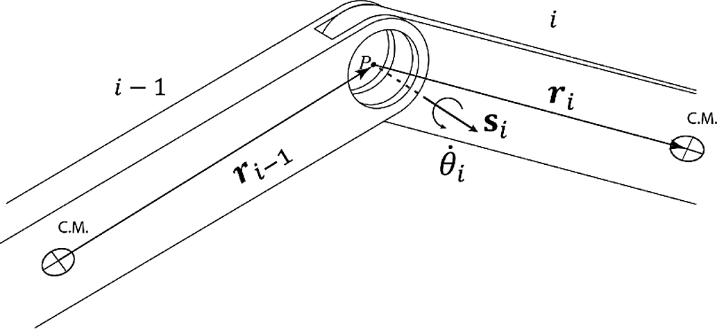
, respectively. For example, if a revolute joint connects two rigid links, as it is shown in Fig. 1, then the following relations hold between the corresponding angular and linear velocities [Reference Taghvaeipour, Angeles and Lessard39]:
 \begin{equation}{\boldsymbol\omega _i} - {\boldsymbol\omega _{i - 1}} = {\dot \theta _i}\kern1pt{{\bf e}_i}\end{equation}
 \begin{equation}\dot{{c}}_{i} - \dot{{c}}_{i - 1} + {{\bf{R}}_i}{\boldsymbol\omega _i} + {{\bf{D}}_{i - 1}}{\boldsymbol\omega _{i - 1}} = 0\end{equation}
Two links connected by a revolute joint.

in which
 ${{\bf{R}}_{i - 1}}$
and
 ${{\bf{R}}_i}$
are the CPM of the vectors
 ${{\bf{r}}_{i - 1}}$
and
 ${{\bf{r}}_i}$
(Fig. 1), respectively. To express the foregoing relations only in terms of twist arrays of the connected rigid links, the passive angular rate
 ${\dot \theta _i}$
should be eliminated. As it was proposed in [Reference Angeles37], this can be obtained by the left multiplying of both sides of Eq. (13a) with the cross product matrix (CPM) of the unit vector
 ${{\bf e}_i}$
, denoting by
 ${{\bf{E}}_i}$
, namely,
 \begin{equation}{{\bf{E}}_i}\left( {{\boldsymbol\omega _i} - {\boldsymbol\omega _{i - 1}}} \right) = 0\end{equation}
In fact, Eqs. (13b) and (14) represent six constraint relations between the kinematic variables of the connected rigid links, of which five are independent. These constraint equations can be readily cast in the format of Eq. (12), which results in the constraint matrices of a revolute joint as follows [Reference Taghvaeipour, Angeles and Lessard39]:
 \begin{equation}{\bf{K}}_{i,i - 1}^J = {\left[ {\begin{array}{{c@{\quad}c}}{{{\bf{E}}_i}}&{{{\bf{O}}_{3 \times 3}}}\\{{{\bf{R}}_{i -{1}}}}&{ -{{\bf 1}_{3 \times 3}}}\end{array}} \right]_{6 \times 6}}\;,\;\;{\bf{K}}_{i,i}^J = {\left[ {\begin{array}{{c@{\quad}c}}{{{\bf{E}}_i}}&{{{\bf{O}}_{3 \times 3}}}\\{{{\bf{R}}_i}}&{{{\bf 1}_{3 \times 3}}}\end{array}} \right]_{6 \times 6}}\end{equation}
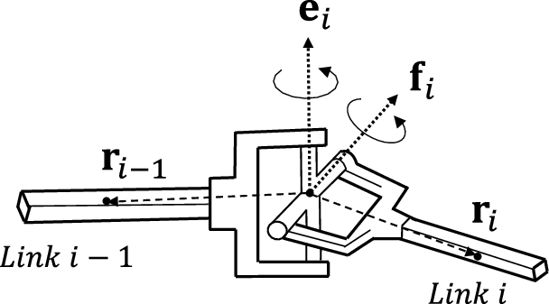
As another example, the constraint matrices of a universal joint (Fig. 2), a kinematic pair with two dofs, can be derived as below [Reference Taghvaeipour, Angeles and Lessard39]
 \begin{equation}{\bf{K}}_{i,i - 1}^J = {\left[ {\begin{array}{{c@{\quad}c}}{ - {{\bf{F}}_i}{{\bf{E}}_i}}&{{{\bf{O}}_{3 \times 3}}}\\{{{\bf{R}}_{i - 1}}}&{ - {{\bf 1}_{3 \times 3}}}\end{array}} \right]_{6 \times 6}},\;\;{\bf{K}}_{i,i}^J = {\left[ {\begin{array}{{c@{\quad}c}}{{{\bf{F}}_i}{{\bf{E}}_i}}&{{{\bf{O}}_{3 \times 3}}}\\{{{\bf{R}}_i}}&{{{\bf 1}_{3 \times 3}}}\end{array}} \right]_{6 \times 6}}\end{equation}
in which
 ${{\bf{F}}_i}$
and
 ${{\bf{E}}_i}$
are the CPM of the unit vectors
 ${{\bf{e}}_i} \times {{\bf{f}}_i}$
and
 ${{\bf{e}}_i}$
, respectively.
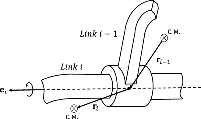
Similarly, the constraint matrices of a cylindrical joint (Fig. 3) can be derived as [Reference Taghvaeipour, Angeles and Lessard39]
 \begin{equation}{\bf{K}}_{i,i - 1}^J = {\left[ {\begin{array}{{c@{\quad}c}}{ - {{\bf{E}}_i}}&{{{\bf{O}}_{3 \times 3}}}\\{{{\bf{E}}_i}{{\bf{R}}_{i - 1}}}&{ - {{\bf{E}}_i}}\end{array}} \right]_{6 \times 6}},\;\;{\bf{K}}_{i,i}^J = {\left[ {\begin{array}{{c@{\quad}c}}{{{\bf{E}}_i}}&{{{\bf{O}}_{3 \times 3}}}\\{{{\bf{E}}_i}{{\bf{R}}_i}}&{{{\bf{E}}_i}}\end{array}} \right]_{6 \times 6}}\end{equation}
Two links connected by a universal joint.

Two links connected by a cylindrical joint.

For all other types of kinematic pairs, the constraint matrices were listed in [Reference Taghvaeipour, Angeles and Lessard39]. By assembling all the constraint equations imposed by kinematic pairs on the rigid links of a multibody system, the following system of constraint equations in a matrix format is obtained:
 \begin{equation}{{\bf{K}}_{\rm{J}}}{\bf{t}} = 0\end{equation}
where
 ${{\bf{K}}_{\rm{J}}}$
is denoting the joint-based CTM, which was introduced in Eq (8).
According to the Chebyshev–Grubler–Kutsbach criterion [Reference Angeles41], the dof of a multibody system is obtained as
 \begin{equation}\tau = 6\left( {n - 1} \right) - \left( {6m - k} \right)\end{equation}
with m and
 $n$
denoting the number of kinematic pairs and links, respectively, and
 $k$
representing the total number of dofs of all kinematic pairs. Therefore, in an inverse dynamic analysis in which the actuator forces/torques and the joint constraint forces/moments are demanded, the number of unknowns equals
 $\tau + 6m - k$
. On the other hand, the Newton–Euler formulation for
 $n - 1\;$
moving rigid links of a multibody system provide
 $6\left( {n - 1} \right)$
equations, which is adequate to calculate all the unknowns. However, with the aforementioned joint-based methodology, regardless of the number of independent constraint equations, the constraint matrix
 ${{\bf{K}}_J}$
is always obtained as a
 $6m \times 6\left( {n - 1} \right)$
matrix. Based on Eq. (8), the dependent constraint equations add
 $k$
unknown joint constraint forces/moments to the system of Eq. (9). Therefore, for a constrained multibody system, the number of unknowns adds up to
 $\tau + 6m$
, which leads to an under-determined system of equations. In this regard, the zero-power relations corresponding to
 $k$
dofs of kinematic pairs (Eq. (10)) provide the required equations needed to solve the problem. It is noteworthy to mention that, in the foregoing joint-based methodology, the influence of active kinematic pairs are treated in the equations separately via the actuator wrench array
 ${}_{}^A{\bf{w}}$
. Therefore, in the calculation of the constraint and joint screw matrices,
 ${{\bf{K}}_{\rm{J}}}$
and
 ${\bf{S}}$
, respectively, all the kinematic pairs must be considered passive.
4. Modified joint-based constraint wrench analysis
As it was seen, the rank deficiency of the previously obtained constraint matrix will be finally resolved down the stream by considering the zero-power relations and screw matrices. However, in this case, the mapping of Eq. (8) cannot be efficiently used to extract indices that reflect some characteristics of a multibody system in terms of the produced constraint wrenches at kinematic pairs.
Therefore, in this section, the joint-based CTM,
 ${{\bf{K}}_J}$
, is obtained by resorting to an alternative approach in which the redundant constraint equations are eliminated. For the sake of simplicity, the method is explained for the revolute and universal joints, and it can be readily generalized for other kinematic pairs. Figure 1 shows two rigid links,
 $i - 1$
and
 $i,$
which are connected by means of a revolute joint. By resorting to the twist transfer formula [Reference Angeles37], the following relations between the twist arrays
 ${\bf{t}}_{i - 1}^i$
and
 ${{\bf{t}}_{i - 1}}$
of two points on the
 ${\left( {i - 1} \right)^{st}}$
rigid body hold:
 \begin{equation}\left\{ {\begin{array}{{c}}{{\unicode[Times]{x1D6DA} }_{i - 1}^i = {\unicode[Times]{x1D6DA} }_{i - 1}^{}}\\{{\bf{v}}_{i - 1}^i = {\bf{v}}_{i - 1}^{} + {\unicode[Times]{x1D6DA} }_{i - 1}^{} \times {{\bf{r}}_{i - 1}}}\end{array}} \right.\mathop \Rightarrow \limits^{{\rm{\;\;\;\;\;\;\;\;\;\;\;\;}}} {\rm{\;}}{\bf{t}}_{i - 1}^i = \left[ {\begin{array}{{c@{\quad}c}}{\bf 1}&{\bf{O}}\\{ - {{\bf{R}}_{i - 1}}}&{\bf 1}\end{array}} \right]{\bf{t}}_{i - 1}^{} = {\bf{G}}_{i - 1}^i{\bf{t}}_{i - 1}^{}\end{equation}
where
 ${{\bf{R}}_{i - 1}}$
is the CPM of vector
 ${{\bf{r}}_{i - 1}}$
, and
 ${\bf{G}}_{i - 1}^i$
denotes the twist transfer matrix between the twist array
 ${\bf{t}}_{i - 1}^i$
of a point on the
 ${i^{th}}$
joint axis which belongs to the
 ${\left( {i - 1} \right)^{st}}$
link and the twist array
 ${{\bf{t}}_{i - 1}}$
of the
 ${\left( {i - 1} \right)^{st}}$
link center of mass. Likewise, the twist transfer formula can be used between the twist arrays
 ${\bf{t}}_i^i$
and
 ${{\bf{t}}_i}$
of two points on the
 ${i^{th}}$
link as follows:
 \begin{equation}\left\{ {\begin{array}{{c}}{{\boldsymbol{\omega }}_i^i = {\boldsymbol{\omega }}_i^{}}\\{{\bf{v}}_i^i = {\bf{v}}_i^{} - {\boldsymbol{\omega }}_i^{} \times {{\bf{r}}_i}}\end{array}} \right.\mathop \Rightarrow \limits^{{\rm{\;\;\;\;\;\;\;\;\;\;\;\;}}} {\bf{t}}_i^i = \left[ {\begin{array}{{c@{\quad}c}}{\bf 1}&{\bf{O}}\\{{{\bf{R}}_i}}&{\bf 1}\end{array}} \right]{\bf{t}}_i^{} = {\bf{G}}_i^i{\bf{t}}_i^{}\end{equation}
where
 ${{\bf{R}}_i}$
is the CPM of vector
 ${{\bf{r}}_i}$
, and
 ${\bf{G}}_i^i$
denotes the twist transfer matrix between the twist array
 ${\bf{t}}_i^i$
of a point on the
 ${i^{th}}$
joint axis which belongs to the link
 $i$
and the twist array
 ${{\bf{t}}_i}$
of the
 ${i^{th}}$
link center of mass. A revolute joint permits relative rotation of the connected bodies about its axis, namely,
 \begin{equation}{\bf{t}}_i^i - {\bf{t}}_{i - 1}^i = {\dot \theta _i}{{\bf{s}}_i}\end{equation}
Substituting twist arrays
 ${\bf{t}}_i^i$
and
 ${\bf{t}}_{i - 1}^i$
from Eqs. (16) and (18), respectively, into Eq. (22) yields
 \begin{equation}{\bf{G}}_i^i{\bf{t}}_i^{} - {\bf{G}}_{i - 1}^i{\bf{t}}_{i - 1}^{} = {\dot \theta _i}{{\bf{s}}_i}\end{equation}
By resorting to the ray coordinates, the wrench array
 ${A_i}{{\bf{s}}_{\bf{i}}}$
, in which the unit of
 ${A_i}$
is N, is composed of the resultant force in the first three components and the resultant moment in the second three components. While the twist array
 ${A_j}{{\bf{s}}_{\bf{j}}}$
, in which the unit of
 ${A_i}$
is rad/s, represents the angular velocity in the first three components and the linear velocity in the second three components [Reference Tsai42]. For a set of screws that span the motion space of a multibody system, there is a set of reciprocal screws which span the corresponding constraint space. The reciprocity condition is obtained by considering the fact that the constraint wrenches do not produce power while the bodies move. Hence, for any screw system
 ${\bf{S}}$
there is a reciprocal screw system
 ${{\bf{S}}^{\rm{r}}}$
which is defined as [Reference Dai, Huang and Lipkin43]
 \begin{equation}{{\bf{S}}^r} \equiv \;\left\{ {{\bf{s}}_j^{\rm{r}}{\rm{|}}{\bf{s}}_j^{\rm{r}}{\boldsymbol{\Gamma }}{{\bf{s}}_i} = 0,\;\forall {{\bf{s}}_i} \in {\bf{S}}} \right\},\;\;{\bf{\Gamma }} = \left[ {\begin{array}{{c@{\quad}c}}{\bf{O}}&{\bf{I}}\\{\bf{I}}&{\bf{O}}\end{array}} \right]\end{equation}
in which I and O are the
 $3 \times 3\;$
identity and zero block matrices, respectively. Apparently, it can be concluded that the screw and reciprocal screw systems, which correspond to the motion and constrained spaces, respectively, are orthogonal to each other. Hence, in the three-dimensional Cartesian space, the following relation between the dimensions of a screw system and its reciprocal counterpart holds:
 \begin{equation}{\rm{dim}}\left( {\bf{S}} \right) + {\rm{dim}}\left( {{{\bf{S}}^{\bf{r}}}} \right) = 6\end{equation}
According to the permitted relative dofs between two rigid bodies which are connected by means of a joint, a joint screw system and the corresponding reciprocal counterpart can be defined, which can be found in the literature [Reference Zhao, Li, Yang and Yu44]. For example, for a revolute joint, the screw system contains only one screw array which can be defined with respect to a reference frame attached to the
 ${i^{th}}$
link on the joint axis, namely,
 \begin{equation}{{\bf{s}}_1} = {{\bf{Q}}_{\rm{i}}} \times {\left[ {\begin{array}{{c@{\quad}c@{\quad}c}}0&0&{\begin{array}{{c@{\quad}c@{\quad}c}}1&0&{\begin{array}{{c@{\quad}c}}0&0\end{array}}\end{array}}\end{array}} \right]^T}\;\end{equation}
where
 ${{\bf{Q}}_i}$
is a
 $6 \times 6\;$
matrix that transforms the attached coordinate frame to the global reference frame [Reference Raoofian, Taghvaeipour and Kamali45]. For the sake of simplicity, it is also assumed that the z-axis of the attached coordinate frame is along the joint axis. The corresponding reciprocal screw system comprises five screw arrays which are presented below [Reference Zhao, Li, Yang and Yu44, Reference Dai and Jones46]
 \begin{equation*}{\bf{s}}_1^r = {\bf{Q}} \times {\left[ {\begin{array}{{c@{\quad}c@{\quad}c}}1&0&{\begin{array}{{c@{\quad}c@{\quad}c}}0&0&{\begin{array}{{c@{\quad}c}}0&0\end{array}}\end{array}}\end{array}} \right]^T} \end{equation*}
 \begin{equation*} {\bf{s}}_2^r = {\bf{Q}} \times {\left[ {\begin{array}{{c@{\quad}c@{\quad}c}}0&1&{\begin{array}{{c@{\quad}c@{\quad}c}}0&0&{\begin{array}{{c@{\quad}c}}0&0\end{array}}\end{array}}\end{array}} \right]^T} \end{equation*}
 \begin{equation*} {\bf{s}}_3^r = {\bf{Q}} \times {\left[ {\begin{array}{{c@{\quad}c@{\quad}c}}0&0&{\begin{array}{{c@{\quad}c@{\quad}c}}1&0&{\begin{array}{{c@{\quad}c}}0&0\end{array}}\end{array}}\end{array}} \right]^T} \end{equation*}
 \begin{equation*} {\bf{s}}_4^r = {\bf{Q}} \times {\left[ {\begin{array}{{c@{\quad}c@{\quad}c}}0&0&{\begin{array}{{c@{\quad}c@{\quad}c}}0&1&{\begin{array}{{c@{\quad}c}}0&0\end{array}}\end{array}}\end{array}} \right]^T}\end{equation*}
 \begin{equation} {\bf{s}}_5^r = {\bf{Q}} \times {\left[ {\begin{array}{{c@{\quad}c@{\quad}c}}0&0&{\begin{array}{{c@{\quad}c@{\quad}c}}0&0&{\begin{array}{{c@{\quad}c}}1&0\end{array}}\end{array}}\end{array}} \right]^T}\;\end{equation}
Accordingly, the reciprocal joint screw matrix of a revolute joint can be defined as
 $${{\bf{S}}_{\rm{r}}} = \;s_1^r\;\;\;\;s_2^r\;\;\;\;s_3^r\;\;\;\;s_4^r\;\;\;\;s_5^r\;$$
By resorting to the definition of reciprocal screws in Eq. (27), Eq. (28) can be left multiplied by
 $\left( {{\bf{S}}_r^T{\bf{\Gamma }}} \right)$
to obtain the following constraint equation in terms of rigid bodies’ twist arrays:
 \begin{equation}{\bf{S}}_r^T\left( {{\boldsymbol{\Gamma G}}_i^i{{\bf{t}}_i} - {\boldsymbol{\Gamma G}}_{i - 1}^i{{\bf{t}}_{i - 1}}} \right) = 0\end{equation}
By comparing Eqs. (26) and (12), the constraint matrices of a revolute joint can be readily obtained as below
 \begin{equation}{\bf{K}}_{i,i - 1}^J = {\bf{S}}_{\rm{r}}^T{{\boldsymbol\Gamma {\bf G}}}_{i + 1}^i\;,\;\;{\bf{K}}_{i,i}^J = {\bf{S}}_{\rm{r}}^T{{\boldsymbol\Gamma {\bf G}}}_i^i\end{equation}
where the size of the above constraint matrices is
 $5 \times 6$
. As a second example, the foregoing procedure is repeated for a universal joint whose axes are initially along the Z and X axes of the global reference frame. As examples of joints with more than one dof, the universal (U) and cylindrical (C) joint are explained in the sequel.
A U joint permits two relative rotations between the connected bodies, namely,
 \begin{equation}{\bf{t}}_i^i - {\bf{t}}_{i - 1}^i = {\dot \theta _{}}\quad{{\bf{s}}_1} +\; {\dot \phi _{}}\;\;\; {{\bf{s}}_2}\end{equation}
By substitution of twist arrays
 ${\bf{t}}_{i - 1}^i$
and
 ${\bf{t}}_i^i$
from Eqs. (16) and (18), respectively, into Eq. (31) it results,
 \begin{equation}{\bf{G}}_i^i{\bf{t}}_i^{} - {\bf{G}}_{i - 1}^i{\bf{t}}_{i - 1}^{} = {\dot \theta _{}}\quad{{\bf{s}}_1} +\; {\dot \phi _{}}\;\;\;{{\bf{s}}_2}\end{equation}
where the screw arrays
 ${{\bf{s}}_1}$
and
 ${{\bf{s}}_2}$
which form the joint screw system is presented below
 \begin{equation*}{{\bf{s}}_1} = {\bf{Q}} \times {\left[ {\begin{array}{{c@{\quad}c@{\quad}c}}0&0&{\begin{array}{{c@{\quad}c@{\quad}c}}1&0&{\begin{array}{{c@{\quad}c}}0&0\end{array}}\end{array}}\end{array}} \right]^T}\end{equation*}
 \begin{equation}{{\bf{s}}_2} = {\bf{Q}} \times {\left[ {\begin{array}{{c@{\quad}c@{\quad}c}}0&1&{\begin{array}{{c@{\quad}c@{\quad}c}}0&0&{\begin{array}{{c@{\quad}c}}0&0\end{array}}\end{array}}\end{array}} \right]^T}\end{equation}
Therefore, the corresponding reciprocal joint screw system has four screw arrays which are listed in the sequel,
 \begin{equation*}{\bf{s}}_1^r = {\bf{Q}} \times {\left[ {\begin{array}{{c@{\quad}c@{\quad}c}}1&0&{\begin{array}{{c@{\quad}c@{\quad}c}}0&0&{\begin{array}{{c@{\quad}c}}0&0\end{array}}\end{array}}\end{array}} \right]^T}\end{equation*}
 \begin{equation*}{\bf{s}}_2^r = {\bf{Q}} \times {\left[ {\begin{array}{{c@{\quad}c@{\quad}c}}0&1&{\begin{array}{{c@{\quad}c@{\quad}c}}0&0&{\begin{array}{{c@{\quad}c}}0&0\end{array}}\end{array}}\end{array}} \right]^T}{\rm{\;}}\end{equation*}
 \begin{equation*}{\bf{s}}_3^r = {\bf{Q}} \times {\left[ {\begin{array}{{c@{\quad}c@{\quad}c}}0&0&{\begin{array}{{c@{\quad}c@{\quad}c}}1&0&{\begin{array}{{c@{\quad}c}}0&0\end{array}}\end{array}}\end{array}} \right]^T}{\rm{\;}}
\end{equation*}
 \begin{equation}{\bf{s}}_4^r = {\bf{Q}} \times {\left[ {\begin{array}{{c@{\quad}c@{\quad}c}}0&0&{\begin{array}{{c@{\quad}c@{\quad}c}}0&1&{\begin{array}{{c@{\quad}c}}0&0\end{array}}\end{array}}\end{array}} \right]^T}{\rm{\;}}\end{equation}
Accordingly, the reciprocal joint screw matrix of a universal joint is defined in the sequel,
 $${{\bf{S}}_r} = \;\left[ {s_1^r\;\;\;\;s_2^r\;\;\;\;s_3^r\;\;\;\;s_4^r} \right]\;$$
By the same token, upon multiplication of Eq. (29) by
 ${\bf{S}}_r^{\rm{T}}{\boldsymbol{\Gamma }}$
, a relation same as Eq. (26) is obtained, and thereafter, the constraint matrices of the U joint can be readily determined. In this case, the size of the constraint matrices is
 $4 \times 6$
.
A cylindrical (C) joint permits relative angular and translational velocities between the connected bodies about and along the joint axis,
 ${\dot \theta _i}$
and
 ${\dot b_i}$
, respectively,
 \begin{equation}{\bf{t}}_i^i - {\bf{t}}_{i - 1}^i = \dot \theta {{\bf{s}}_1} + \dot b{{\bf{s}}_2}\end{equation}
Upon substitution of twist arrays
 ${\bf{t}}_{i - 1}^i$
and
 ${\bf{t}}_i^i$
from Eqs. (16) and (18), respectively, into Eq. (36) it yields
 \begin{equation}{\bf{G}}_i^i{\bf{t}}_i^{} - {\bf{G}}_{i - 1}^i{\bf{t}}_{i - 1}^{} = \dot \theta {{\bf{s}}_1} + \dot b{{\bf{s}}_2}\end{equation}
where the screw arrays
 ${{\bf{s}}_1}$
and
 ${{\bf{s}}_2}$
are
 \begin{equation*}{{\bf{s}}_1} = {\bf{Q}} \times {\left[ {\begin{array}{{c@{\quad}c@{\quad}c}}0&0&{\begin{array}{{c@{\quad}c@{\quad}c}}1&0&{\begin{array}{{c@{\quad}c}}0&0\end{array}}\end{array}}\end{array}} \right]^T} \end{equation*}
 \begin{equation}{{\bf{s}}_2} = {\bf{Q}} \times {\left[ {\begin{array}{{c@{\quad}c@{\quad}c}}0&0&{\begin{array}{{c@{\quad}c@{\quad}c}}0&0&{\begin{array}{{c@{\quad}c}}0&1\end{array}}\end{array}}\end{array}} \right]^T}\end{equation}
Therefore, the four corresponding reciprocal joint screws can be written as
 \begin{equation*}{\bf{s}}_1^r = {\bf{Q}} \times {\left[ {\begin{array}{{c@{\quad}c@{\quad}c}}1&0&{\begin{array}{{c@{\quad}c@{\quad}c}}0&0&{\begin{array}{{c@{\quad}c}}0&0\end{array}}\end{array}}\end{array}} \right]^T}{\rm{\;}} \end{equation*}
 \begin{equation*}{\bf{s}}_2^r = {\bf{Q}} \times {\left[ {\begin{array}{{c@{\quad}c@{\quad}c}}0&1&{\begin{array}{{c@{\quad}c@{\quad}c}}0&0&{\begin{array}{{c@{\quad}c}}0&0\end{array}}\end{array}}\end{array}} \right]^T}{\rm{\;}} \end{equation*}
 \begin{equation*}{\bf{s}}_3^r = {\bf{Q}} \times {\left[ {\begin{array}{{c@{\quad}c@{\quad}c}}0&0&{\begin{array}{{c@{\quad}c@{\quad}c}}0&1&{\begin{array}{{c@{\quad}c}}0&0\end{array}}\end{array}}\end{array}} \right]^T}{\rm{\;}}\end{equation*}
 \begin{equation}{\bf{s}}_4^r = {\bf{Q}} \times {\left[ {\begin{array}{{c@{\quad}c@{\quad}c}}0&0&{\begin{array}{{c@{\quad}c@{\quad}c}}0&0&{\begin{array}{{c@{\quad}c}}1&0\end{array}}\end{array}}\end{array}} \right]^T}{\rm{\;}}\end{equation}
which form the reciprocal joint screw matrix similar to what was defined for the U joint in Eq. (35). For any other type of kinematic pairs, it is only needed to replace the corresponding reciprocal joint screw matrix in Eq. (26) and obtain the corresponding joint constraint matrices. Same as what was explained in the previous section, the new joint-based CTM of a multibody system,
 ${{\bf{K}}_J}$
, can be obtained by assembling the constraint matrices of all kinematic pairs. In contrast to the previous joint-based method, in this approach, all the constraint equations are independent, and hence,
 ${{\bf{K}}_J}$
is obtained as a
 $\left( {6m - k} \right) \times 6\left( {n - 1} \right)$
full-rank matrix. Therefore, for a determined multibody system, the number of unknowns becomes
 $\tau + 6m - k$
, which is equal to the number of Newton–Euler equations. In other words, with this new formation of the joint-based CTM,
 ${{\bf{K}}_J}$
, the Newton–Euler equations suffice to solve the problem, namely,
 \begin{equation}\left[ {\begin{array}{{c@{\quad}c}}{{\bf{K}}_{\rm{J}}^T}&{{}_{}^A{\bf{T}}}\end{array}} \right]\left[ {\begin{array}{{c}}{\boldsymbol{\lambda }}\\{\bf{\tau }}\end{array}} \right] = \left[ {\begin{array}{{c}}{\unicode[Times]{x1D6C8} }\\0\end{array}} \right]\end{equation}
Thus, in this approach, there is no need to augment the zero-power relations of kinematic pairs (Eq. (10)) to the system of equations.
5. Link-based constraint wrench analysis
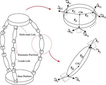
This methodology is somehow direct utilization of the Newton–Euler formulation, which was tailored for the constraint wrench analysis of complex mechanisms by means of screw, twist, and wrench definitions. In contrast to the joint-based approaches, this method does not resort on the kinematic constraint equations which are imposed by the kinematic pairs of multibody system. In other words, instead of focusing on the joints and their kinematic relations, it focuses on the links and the applied and constraint wrenches. In this approach, for each rigid link, the constraint and applied forces/moments are simply transferred to the center of mass by means of the wrench transfer formula [Reference Ghaedrahmati, Raoofian, Kamali and Taghvaeipour40]. Figure 4 shows a multi-node link of a parallel manipulator, denoted by
 $l$
, which is connected to
 $a$
number of links by means of
 $a$
kinematic pairs which are labeled as
 ${l_1},{l_2},\; \ldots ,\;{l_a}.$
The position vector of center of mass of the
 ${l^{th}}$
link from the
 ${i^{th}}$
joint is represented by
 ${{\bf{r}}_{li}}$
in which
 $i = 1,\;2, \ldots ,\;a.$
Also,
 ${}_{}^f{{\boldsymbol{\lambda }}_{li}}$
and
 ${}_{}^m{{\boldsymbol{\lambda }}_{li}}$
denote the constraint force and moment vectors, respectively, which are imposed by the
 ${i^{th}}$
joint on the link
 $l$
. These constraint forces and moments are transferred to the center of mass of the link by the following relation:
 \begin{equation*}{}_{}^C{{\bf{m}}_l} = \left( {{}_{}^m{{\boldsymbol{\lambda }}_{l1}} + {r_{l1}} \times {}_{}^f{{\boldsymbol{\lambda }}_{l1}}} \right) + \left( {{}_{}^m{{\boldsymbol{\lambda }}_{l2}} + {r_{l2}} \times {}_{}^f{{\boldsymbol{\lambda }}_{l2}}} \right) + \ldots + \;\left( {{}_{}^m{{\boldsymbol{\lambda }}_{la}} + {r_{la}} \times {}_{}^f{{\boldsymbol{\lambda }}_{la}}} \right)\end{equation*}
 \begin{equation}{}_{}^C{{\bf{f}}_l} = \;{}_{}^f{{\boldsymbol{\lambda }}_{l1}} + {}_{}^f{{\boldsymbol{\lambda }}_{l1}} + \ldots + {}_{}^f{{\boldsymbol{\lambda }}_{la}}\end{equation}
in which
 ${}_{}^C{{\bf{f}}_l}$
and
 ${}_{}^C{{\bf{m}}_l}$
are the transferred constraint force and moment vectors, respectively. The six-dimensional constraint wrench array at the joints or at the center of mass of the link can be formed as
 \begin{equation}{}_{}^C{{\bf{w}}_l} = \;\left[ {\begin{array}{{c}}{{}_{}^C{{\bf{m}}_l}}\\{{}_{}^C{{\bf{f}}_l}}\end{array}} \right],\;\;{{\boldsymbol{\lambda }}_i} = \;\left[ {\begin{array}{{c}}{{}_{}^m{{\boldsymbol{\lambda }}_{li}}}\\{{}_{}^f{{\boldsymbol{\lambda }}_{li}}}\end{array}} \right]\end{equation}
A schematic of a two-node and a multi-node link in a parallel mechanism.

With the definition of the constraint wrenches, Eq. (41) can be rewritten as below [Reference Ghaedrahmati, Raoofian, Kamali and Taghvaeipour40]
 \begin{equation}{}_{}^c{{\bf{w}}_l} = {\bf{K}}_{l1}^L{{\boldsymbol{\lambda }}_{l1}} + {\bf{K}}_{l2}^L{{\boldsymbol{\lambda }}_{l2}} + \ldots + {\bf{K}}_{la}^L{{\boldsymbol{\lambda }}_{la}}\end{equation}
where
 ${\bf{K}}_{li}^L$
is called the constraint transfer matrix (CTM) of the
 ${i^{th}}$
joint of the link
 $l$
, namely,
 \begin{equation}{\bf{K}}_{lj}^L = {\left[ {\begin{array}{{c@{\quad}c}}{ -{\bf 1}}&{ - {}_{}^l{{\bf{R}}_{li}}}\\{\bf{O}}&{\bf 1}\end{array}} \right]_{6 \times 6}}\;\;,\;\;i = 1,\;2, \ldots ,\;a\end{equation}
For a 2-node link, denoted by
 $\beta $
, Eq. (43) is reduced to the following relation:
 \begin{equation}{}_{}^c{{\bf{w}}_\beta } = {\bf{K}}_{\beta i}^L{{\boldsymbol{\lambda }}_i} + {\bf{K}}_{\beta j}^L{{\boldsymbol{\lambda }}_j}\end{equation}
Upon assembling of the CTM of all rigid links, the CTM of the multibody system,
 ${{\bf{K}}^L}$
, is simply obtained [Reference Ghaedrahmati, Raoofian, Kamali and Taghvaeipour40], which is a
 $6\left( {n - 1} \right) \times 6m$
singular matrix. In fact, in the link-based constraint wrench analysis, regardless of the type of kinematic pair, three constraint forces,
 ${}_{}^f{\lambda _i}$
, and three constraint moments,
 ${}_{}^m{\lambda _i}$
, where
 $i = 1,2,3$
, are considered at each joint. Therefore, the number of unknowns for a determined system becomes
 $\tau + 6m$
, while there are only
 $6\left( {n - 1} \right)$
Newton–Euler equations. Hence, same as the joint-based method introduced in sec. 3, in order to compute the unknowns,
 $k$
zero-power relations for all kinematic pairs should be taken into account (Eq. (8)).
6. Constraints distribution indices
Engineers and researchers are always looking for performance indices to quantitatively evaluate the kinematical, dynamical or structural behavior of a complex system. In such systems, there are characteristic matrices, such as Jacobian, stiffness, and mass matrices, which correspond to the aforementioned behavior. Based on these characteristic matrices, researchers have tried to define proper performance indices, such as kinematic index [Reference Ghaedrahmati, Raoofian, Kamali and Taghvaeipour40], dynamic indices [Reference Zhao and Gao17, Reference Angeles41], and stiffness indices [Reference Zhao and Gao17, Reference Angeles41,Reference Mo, Shao, Guan, Xie and Tang19, Reference Raoofian, Taghvaeipour and Kamali45, Reference Gosselin and Angeles47–Reference Chen, Peng, Yan, Li, Wei, Fan, Tang and Zhu49]. In the current study, the CTM was also introduced as another pivotal matrix in mechanical systems which transfers the constraint wrenches from the joints to the center of mass of links. In another point of view, the CTM can be seen as a mapping that distributes the applied forces/moments over the joints. A uniform distribution of forces and moments in a mechanism is demanding as it prevents a sudden failure of a joint or a link, and thus, extracting proper constraint wrench distribution indices, which show this uniformity can be an achievement. The three methodologies which were explained in the previous sections provide distinct CTMs with different properties and dimensions; however, the modified joint-based method is the only one that can attain a full-rank CTM. Therefore, this matrix is targeted to obtain the constraint wrench distribution indices. In this regard, first, Eq. (8) is rewritten in the following general form:
 \begin{equation}{\bf{w}} = {\bf{K}\boldsymbol{\lambda }}{\rm{\;\;\;\;\;}}\end{equation}
in which w and
 ${\boldsymbol{\lambda }}$
are denoting the applied and joints constraint wrench arrays, respectively. The wrench arrays are composed of moment and force vectors, and hence, the components of the matrix K comprise different units. To distinguish between constraint moments and forces, in the next step, the moment and force components of each constraint wrench array are gathered into the separated arrays with subscripts m and f, respectively, namely,
 \begin{equation}\left[ {\begin{array}{{c}}{{{\bf{w}}_m}}\\{{{\bf{w}}_f}}\end{array}} \right] = \left[ {\begin{array}{{c@{\quad}c}}{{{\bf{K}}_{11}}}&{{{\bf{K}}_{12}}}\\{{{\bf{K}}_{21}}}&{{{\bf{K}}_{22}}}\end{array}} \right]\left[ {\begin{array}{{c}}{{{\boldsymbol{\lambda }}_m}}\\{{{\boldsymbol{\lambda }}_f}}\end{array}} \right]{\rm{\;\;\;\;\;}}\end{equation}
where block matrices
 ${{\bf{K}}_{11}}$
and
 ${{\bf{K}}_{22}}$
are dimensionless and
 ${{\bf{K}}_{12}}$
,
 ${{\bf{K}}_{21}}$
have units of
 $m$
and
 ${m^{ - 1}}$
, respectively. The moment and force equations can then be expanded as follows:
 \begin{equation}\begin{array}{*{20}{c}}{{{\bf{w}}_m} = {{\bf{K}}_{11}}{{\boldsymbol{\lambda }}_m} + {{\bf{K}}_{12}}{\rm{\;}}{{\boldsymbol{\lambda }}_f} = {{\bf{w}}_{{\rm{mm}}}} + {{\bf{w}}_{{\rm{mf}}}}{\rm{\;\;}}}\\{{{\bf{w}}_f} = {{\bf{K}}_{21}}{{\boldsymbol{\lambda }}_m} + {{\bf{K}}_{22}}{{\boldsymbol{\lambda }}_f} = {{\bf{w}}_{{\rm{fm}}}} + {{\bf{w}}_{{\rm{ff}}}}\;}\end{array}\end{equation}
In which
 ${{\bf{w}}_{{\rm{mm}}}}$
and
 ${{\bf{w}}_{{\rm{mf}}}}$
are the parts of the applied moments which are transformed to the moment and force constraints, respectively. With the same token,
 ${{\bf{w}}_{{\rm{fm}}}}$
and
 ${{\bf{w}}_{{\rm{ff}}}}$
are the parts of the applied forces which are treated as moment and force constraints, respectively. The norm of each independent part of Eq. (48) can be considered as a physically meaningful quadratic form [Reference Kövecses and Ebrahimi48], that is,
 $\|{{\bf{w}}_{m{\delta} }}\|^2 = {{\unicode[Times]{x1D6C5} }^{\bf T}}{\bf{K}}_{ij}^T{\bf{K}}_{ij}^{}{{\unicode[Times]{x1D6C5} }^{}}$
, which defines an ellipsoid in the space of
 ${\unicode[Times]{x1D6C5} }$
, which can be force or moment, depending on the chosen part. The matrix of the eigenvectors of
 ${\bf{K}}_{ij}^T{\bf{K}}_{ij}^{}$
is then used as an orthogonal transformation which maps the vector of dimensionless parameters
 ${{\bf{p}}_\delta }$
to
 ${\unicode[Times]{x1D6C5} }$
, namely[Reference Taghvaeipour, Angeles and Lessard50],
 \begin{equation}{\unicode[Times]{x1D6C5} } = {{\bf{S}}_\delta }{{\bf{p}}_\delta }\end{equation}
As a result, there will be a linear transformation regarding the constraint moments and forces which are produced by the applied moment array
 ${{\bf{w}}_m}$
as [Reference Taghvaeipour, Angeles and Lessard50]
 \begin{equation}\left[ {\begin{array}{{c}}{{{\boldsymbol{\lambda }}_m}}\\{{{\boldsymbol{\lambda }}_f}}\end{array}} \right] = \left[ {\begin{array}{{c@{\quad}c}}{{{\bf{S}}_m}}&{\bf{O}}\\{\bf{O}}&{{{\bf{S}}_f}}\end{array}} \right]\left[ {\begin{array}{{c}}{{{\unicode[Times]{x1D6D9} }_m}}\\{{{\unicode[Times]{x1D6D9} }_f}}\end{array}} \right]\end{equation}
and another one for the constraint moments and forces which are produced by the applied force array
 ${{\bf{w}}_f}$
as
 \begin{equation}\left[ {\begin{array}{{c}}{{{\boldsymbol{\lambda }}_m}}\\{{{\boldsymbol{\lambda }}_f}}\end{array}} \right] = \left[ {\begin{array}{{c@{\quad}c}}{{{\bf{H}}_m}}&{\bf{O}}\\{\bf{O}}&{{{\bf{H}}_f}}\end{array}} \right]\left[ {\begin{array}{{c}}{{{\boldsymbol{\chi }}_m}}\\{{{\boldsymbol{\chi }}_f}}\end{array}} \right]\end{equation}
Upon substitution of Eqs. (50) and (51) into Eq. (48), the applied moment and force arrays are transformed into dimensionless parameter vectors via the following linear transformations [Reference Taghvaeipour, Angeles and Lessard50]:
 \begin{equation*}{{\bf{w}}_m} = {{\bf{G}}_m}{\unicode[Times]{x1D6D9} }\;\;,\;{{\bf{w}}_f} = {{\bf{G}}_f}\;{\boldsymbol{\chi }}\end{equation*}
 \begin{equation}{\unicode[Times]{x1D6D9} } = \left[ {\begin{array}{{c}}{{{\unicode[Times]{x1D6D9} }_m}}\\{{{\unicode[Times]{x1D6D9} }_f}}\end{array}} \right]\;,\;\;{\boldsymbol{\chi }} = \left[ {\begin{array}{{c}}{{{\boldsymbol{\chi }}_m}}\\{{{\boldsymbol{\chi }}_f}}\end{array}} \right]\end{equation}
where
 ${{\bf{G}}_m}$
and
 ${{\bf{G}}_f}$
are rectangular unit homogeneous coefficient matrices which are defined as
 \begin{equation}\begin{array}{{c}}{{{\bf{G}}_m} = \left[ {\begin{array}{{c@{\quad}c}}{{{\bf{K}}_{11}}{{\bf{S}}_m}}&{{{\bf{K}}_{12}}{{\bf{S}}_f}}\end{array}} \right]\;}\\[5pt]{{{\bf{G}}_f} = \left[ {\begin{array}{{c@{\quad}c}}{{{\bf{K}}_{21}}{{\bf{H}}_m}}&{{{\bf{K}}_{22}}{{\bf{H}}_f}}\end{array}} \right]}\end{array}\;\end{equation}
The eigenvalues of
 ${\bf{G}}_m^T{{\bf{G}}_m}$
and
 ${\bf{G}}_f^T{{\bf{G}}_f}$
characterize the distortion of the unit hyperspheres of
 $\|{w_m}\|^{2} = 1$
and
 $\|{w_f}\|^{2} = 1$
, respectively. With
 ${\mu _i}$
and
 ${\xi _i}$
denoting the eigenvalues of
 ${\bf{G}}_m^T{{\bf{G}}_m}$
and
 ${\bf{G}}_f^T{{\bf{G}}_f}$
, respectively, the ratios of the maximum to the minimum eigenvalues, which is referred to as the Condition number, are defined as
 \begin{equation}\Phi_{m}=\frac{\text{max}(\mu_i)}{\text{min}(\mu_i)}, \Phi_{f}=\frac{\text{max}(\xi_{i})}{\text{min}(\xi_{i})}\end{equation}
where
 ${\phi _m}$
and
 ${\phi _f}$
are referred to as the constraint moments and forces distribution indices, respectively. It is expected that an ideal distribution of constraint moments and forces happens when these indices approach unity, and unbalanced distribution of constraint moments and forces occurs as much as the indices attain values greater than one. The claim will be investigated numerically in the following case studies.
7. Case study A: A spherical four-bar linkage
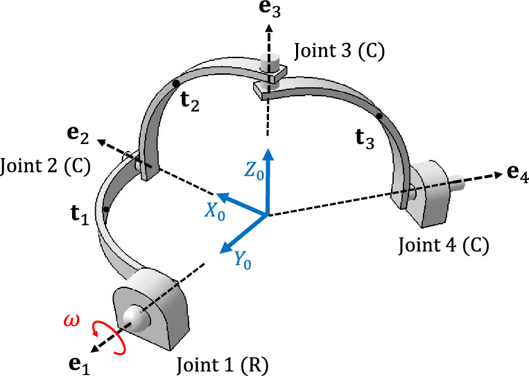
To explain the key steps of the proposed approaches, here, the constraint wrench analysis of a spherical four bars linkage is conducted. The mechanism is considered as RCCC, in which R and C are denoting the revolute and cylindrical joint, respectively. In fact, the aforementioned kinematic chain is an isoconstrained version of the mechanism which is kinematically similar to the RRRR counterpart yet without redundant constraints. The schematic of the mechanism including the global reference frame, and joints axes (
 ${{\bf{e}}_i}$
) are shown in Fig. 5. In this case, when an input joint motion, is known, the angular rates of other joints can be readily calculated via the kinematic Eq. (51). Therefore, with the known kinematic variables and physical and geometrical properties of the rigid links, the vector
 ${\unicode[Times]{x1D6C8} }$
in Eq. (11) is already available.
Spherical four-bar linkage.

Based on the joint-based method, Eq. (12) needs to be written for all four joints which connect four rigid bodies, including the ground, namely,
 \begin{equation*}{\bf{K}}_{1,0}^R{{\bf{t}}_0} + {\bf{K}}_{1,1}^R{{\bf{t}}_1} = 0\end{equation*}
 \begin{equation*}{\bf{K}}_{2,1}^C{{\bf{t}}_1} + {\bf{K}}_{2,2}^C{{\bf{t}}_2} = 0\end{equation*}
 \begin{equation*}{\bf{K}}_{3,2}^C{{\bf{t}}_2} + {\bf{K}}_{3,3}^C{{\bf{t}}_3} = 0\end{equation*}
 \begin{equation}{\bf{K}}_{4,3}^C{{\bf{t}}_3} + {\bf{K}}_{4,4}^C{{\bf{t}}_4} = 0\end{equation}
in which
 ${\bf{K}}_{i,j}^R$
are the CTMs of the revolute joint, which is defined based on Eq. (15). As
 ${{\bf{t}}_0}$
belongs to the ground and equals zero, only
 ${\bf{K}}_{1,1}^R$
needs to be quantified,
 \begin{equation}{\bf{K}}_{1,1}^R = {\left[ {\begin{array}{{c@{\quad}c}}{{{\bf{E}}_1}}&{\bf{O}}\\{{{\bf{D}}_1}}&{\bf 1}\end{array}} \right]_{6 \times 6}}\end{equation}
The CTMs of the cylindrical joints are denoted by
 ${\bf{K}}_{i,j}^C$
which were defined in Eq. (17), namely,
 \begin{equation*}\;\;{\bf{K}}_{i,i - 1}^C = {\left[ {\begin{array}{{c@{\quad}c}}{ - {{\bf{E}}_i}}&{\bf{O}}\\{{{\bf{E}}_i}{{\bf{R}}_{i - 1}}}&{ - {{\bf{E}}_i}}\end{array}} \right]_{6 \times 6}}{\rm{\;and}}\;\;\;{\bf{K}}_{i,i}^C = {\left[ {\begin{array}{{c@{\quad}c}}{{{\bf{E}}_i}}&{\bf{O}}\\{{{\bf{E}}_i}{{\bf{D}}_i}}&{{{\bf{E}}_i}}\end{array}} \right]_{6 \times 6}}{\rm{\;\;for}}\;\;i = 2,\;3\;\end{equation*}
 \begin{equation}{\bf{K}}_{4,3}^C = {\left[ {\begin{array}{{c@{\quad}c}}{{{\bf{E}}_4}}&{\bf{O}}\\{{{\bf{E}}_4}{{\bf{R}}_3}}&{ - {{\bf{E}}_4}}\end{array}} \right]_{6 \times 6}}\end{equation}
In the abovementioned relations,
 ${{\bf{E}}_i}$
is denoting the CPM of the joints axis
 ${{\bf{e}}_i}$
, and
 ${{\bf{D}}_i}$
and
 ${{\bf{R}}_i}$
are the CPM of the position vectors of the joints to the links’ center of mass,
 ${{\unicode[Times]{x1D6D2} }_{i}}$
and
 ${{\unicode[Times]{x1D6C4} }_{i}}$
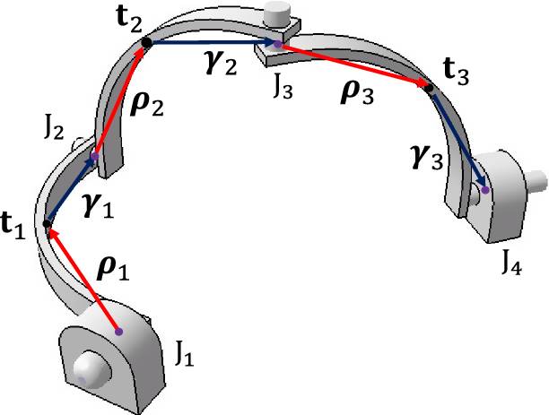
, respectively, as it is shown in Fig. 6. Considering that
 ${{\bf{t}}_0} = {{\bf{t}}_4} = {\bf 0}$
, the system twist vector is defined as
 ${\bf{t}} = \;{\left[ {\begin{array}{{c@{\quad}c@{\quad}c}}{{\bf{t}}_1^T}&{{\bf{t}}_2^T}&{{\bf{t}}_3^T}\end{array}} \right]^T}$
, and thus, the joint-based CTM of the mechanism
 ${{\bf{K}}_J}$
is readily obtained as
 \begin{equation}{{\bf{K}}_J} = {\left[ {\begin{array}{{c@{\quad}c@{\quad}c}}{{\bf{K}}_{1,1}^R}&{\bf{O}}&{\bf{O}}\\{{\bf{K}}_{2,1}^C}&{{\bf{K}}_{2,2}^C}&{\bf{O}}\\{\bf{O}}&{{\bf{K}}_{3,2}^C}&{{\bf{K}}_{3,3}^C}\\{\bf{O}}&{\bf{O}}&{{\bf{K}}_{4,3}^C}\end{array}} \right]_{24 \times 18}}\end{equation}
Position vectors of the mass center of the links.

A similar procedure can be adopted to obtain the modified joint-based CTM of the mechanism. According to Eqs. (20) and (21),
 ${\bf{G}}_j^i$
of the rigid bodies can be established as below
 \begin{equation}\;\;{\bf{G}}_1^1 = {\left[ {\begin{array}{{c@{\quad}c}}{\bf 1}&{\bf{O}}\\{{{\bf{D}}_1}}&{\bf 1}\end{array}} \right]_{6 \times 6}}{\rm{\;}},{\rm{\;\;}}\end{equation}
 \begin{equation*}\;\;{\bf{G}}_{i - 1}^i = {\left[ {\begin{array}{{c@{\quad}c}}{ -{\bf 1}}&{\bf{O}}\\{{{\bf{R}}_{i - 1}}}&{ -{\bf 1}}\end{array}} \right]_{6 \times 6}}{\rm{\;and}}\;\;\;{\bf{G}}_i^i = {\left[ {\begin{array}{{c@{\quad}c}}{\bf 1}&{\bf{O}}\\{{{\bf{D}}_i}}&{\bf 1}\end{array}} \right]_{6 \times 6}}{\rm{\;\;for}}\;i = 2,\;3\;\;,\;\end{equation*}
 \begin{equation*}{\bf{G}}_4^3 = {\left[ {\begin{array}{{c@{\quad}c}}{ -{\bf 1}}&{\bf{O}}\\{{{\bf{R}}_3}}&{ -{\bf 1}}\end{array}} \right]_{6 \times 6}}\end{equation*}
Referring to Eqs. (28) and (30) and the reciprocal joint screw matrices of the revolute and cylindrical joints, the joints modified CTMs can be calculated. Therefore, the modified joint-based CTM of the mechanism can be written as below
 \begin{equation}{{\bf{K}}_J} = {\left[ {\begin{array}{{c@{\quad}c@{\quad}c}}{{\bf{K}}_{1,1}^J}&{\bf{O}}&{\bf{O}}\\{{\bf{K}}_{2,1}^J}&{{\bf{K}}_{2,2}^J}&{\bf{O}}\\{\bf{O}}&{{\bf{K}}_{3,2}^J}&{{\bf{K}}_{3,3}^J}\\{\bf{O}}&{\bf{O}}&{{\bf{K}}_{4,3}^J}\end{array}} \right]_{17 \times 18}}\end{equation}
Apparently, the rank deficiency of the joint-based CTM (Eq. (18)) is now resolved in the modified version.
In the link-based methodology, because the mechanism is only made of 2-node rigid links, the corresponding CTMs can be simply written based on Eq. (44)., namely,
 \begin{equation}\;\;{\bf{K}}_{i,i}^L = {\left[ {\begin{array}{{c@{\quad}c}}{\bf 1}&{ - {{\bf{D}}_i}}\\{\bf{O}}&{bf 1}\end{array}} \right]_{6 \times 6}}{\rm{\;}},{\rm{\;\;}}{\bf{K}}_{i,i + 1}^L = {\left[ {\begin{array}{{c@{\quad}c}}{ -{\bf 1}}&{ - {{\bf{R}}_i}}\\{\bf{O}}&{ -{\bf 1}}\end{array}} \right]_{6 \times 6}}{\rm{\;\;for}}\;i = 1,2,\;3\end{equation}
Accordingly, the CTM of the mechanism can be formed as below
 \begin{equation}{{\bf{K}}_L} = {\left[ {\begin{array}{{c@{\quad}c@{\quad}c@{\quad}c}}{{\bf{K}}_{1,1}^L}&{{\bf{K}}_{1,2}^L}&{\bf{O}}&{\bf{O}}\\{\bf{O}}&{{\bf{K}}_{2,2}^L}&{{\bf{K}}_{2,3}^L}&{\bf{O}}\\{\bf{O}}&{\bf{O}}&{{\bf{K}}_{3,3}^L}&{{\bf{K}}_{3,4}^L}\end{array}} \right]_{18 \times 24}}\end{equation}
In contrast to the modified joint-based, the joint-based and the link-based methodologies need the screw matrix
 ${\bf{S}}$
to calculate the unknowns. This matrix is composed of the joints screw matrices which are placed in the following format [Reference Taghvaeipour, Angeles and Lessard39]:
 \begin{equation}{\bf{S}} = {\left[ {\begin{array}{{c@{\quad}c@{\quad}c@{\quad}c}}{{{\bf{S}}_1}}&{\bf{O}}&{\bf{O}}&{\bf{O}}\\{\bf 0}&{{{\bf{S}}_2}}&{\bf{O}}&{\bf{O}}\\{\bf 0}&{\bf{O}}&{{{\bf{S}}_3}}&{\bf{O}}\\{\bf 0}&{\bf{O}}&{\bf{O}}&{{{\bf{S}}_4}}\end{array}} \right]_{24 \times 7}}\end{equation}
where
 \begin{equation}{{\bf{S}}_1} = {\left[ {\begin{array}{{c}}{{{\bf{e}}_1}}\\{\bf 0}
\end{array}} \right]_{6 \times 1}}{\rm{\;}},{\rm{\;\;\;}}{{\bf{S}}_i} = {\left[ {\begin{array}{{c@{\quad}c}}{{{\bf{e}}_i}}&{\bf 0}\\{\bf 0}&{{{\bf{e}}_i}}\end{array}} \right]_{6 \times 2}}\;{\rm{for}}\;i = 2,\;3\;,4\end{equation}
As the only active joint in the mechanism is the revolute, the actuator wrench shaping matrix
 ${}_{}^A{\bf{T}}$
is simply obtained as
 \begin{equation}{{\bf{T}}^A} = {\left[ {\begin{array}{*{20}{c}}{{{\bf{S}}_1}}\\{\bf 0}\end{array}} \right]_{18 \times 1}}\end{equation}
For each methodology, the constraint wrench array encompasses different dimensions and components. These arrays, belonging to different methods, are represented below separately,
 \begin{equation}{{\boldsymbol{\lambda }}^J} = {\left[ {\begin{array}{{c}}{{\boldsymbol{\lambda }}_{{1_{6 \times 1}}}^J}\\[4pt]{{\boldsymbol{\lambda }}_{{2_{6 \times 1}}}^J}\\[4pt]{\begin{array}{{c}}{{\boldsymbol{\lambda }}_{{3_{6 \times 1}}}^J}\\[4pt]{{\boldsymbol{\lambda }}_{{4_{6 \times 1}}}^J}\end{array}}\end{array}} \right]_{24 \times 1}}\;,\;\;{{\boldsymbol{\lambda }}^{MJ}} = {\left[ {\begin{array}{{c}}{{\boldsymbol{\lambda }}_{{1_{5 \times 1}}}^{MJ}}\\[4pt]{{\boldsymbol{\lambda }}_{{2_{4 \times 1}}}^{MJ}}\\[4pt]{\begin{array}{{c}}{{\boldsymbol{\lambda }}_{{3_{4 \times 1}}}^{MJ}}\\[4pt]{{\boldsymbol{\lambda }}_{{4_{4 \times 1}}}^{MJ}}\end{array}}\end{array}} \right]_{17 \times 1}}\;,\;\;{{\boldsymbol{\lambda }}^L} = {\left[ {\begin{array}{{c}}{{\boldsymbol{\lambda }}_{{1_{6 \times 1}}}^L}\\[4pt]{{\boldsymbol{\lambda }}_{{2_{6 \times 1}}}^L}\\[4pt]{\begin{array}{{c}}{{\boldsymbol{\lambda }}_{{3_{6 \times 1}}}^L}\\[4pt]{{\boldsymbol{\lambda }}_{{4_{6 \times 1}}}^L}\end{array}}\end{array}} \right]_{24 \times 1}}\end{equation}
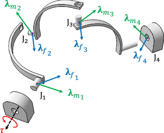
Although the components of the above arrays have the nature of constraint moments (
 ${{\boldsymbol{\lambda }}_m}$
) and forces (
 ${{\boldsymbol{\lambda }}_f}$
) exerted at the joints (Fig. 7), they do not share similar meaning. This concept will be discussed in further detail later.
The constraint wrench moments and forces exerted at the joints.

To evaluate the methodologies on the spherical mechanism with known physical and geometrical properties, a dynamic problem is proposed in which the angular value of revolute joint obeys a simple harmonic function such as
 ${\theta _1} = {\rm{sin}}\left( t \right)$
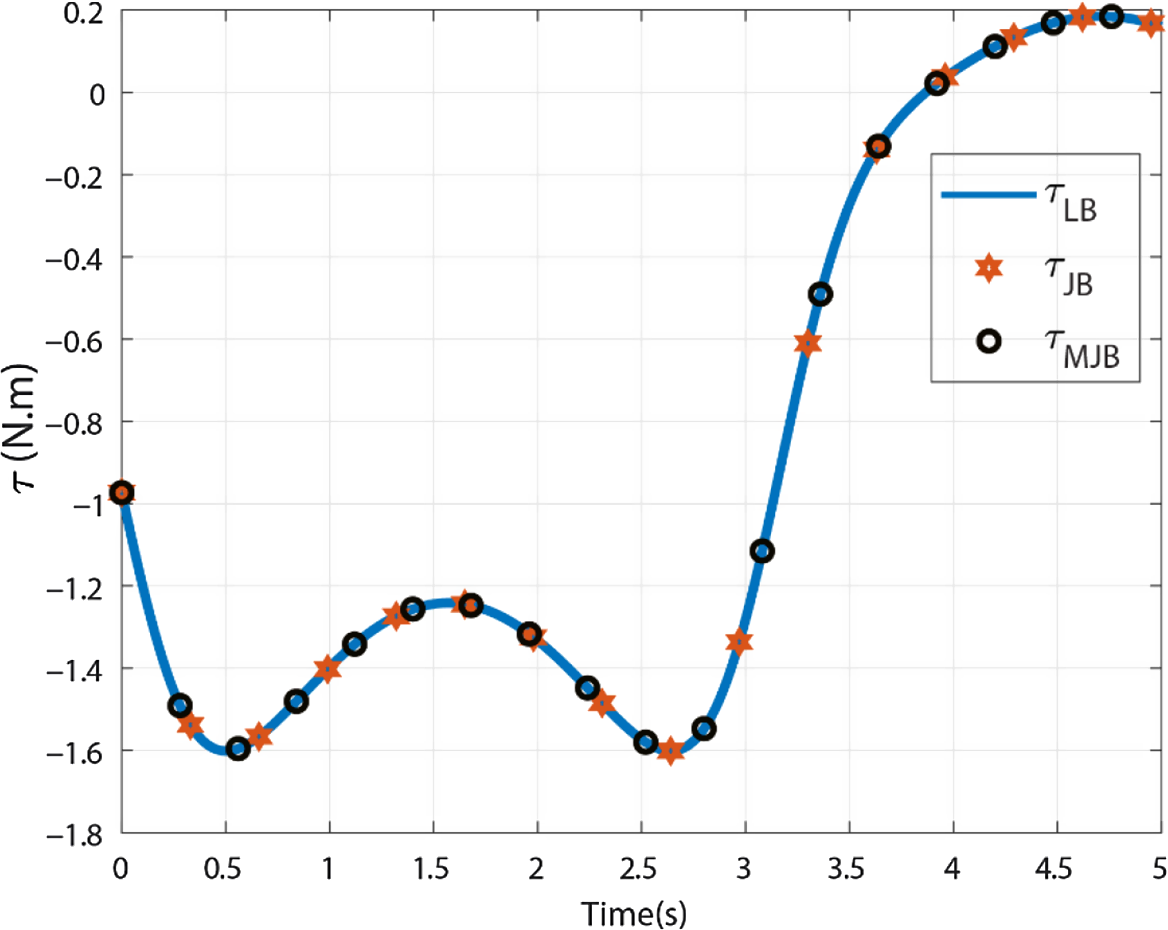
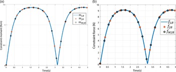
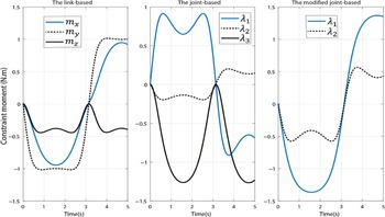
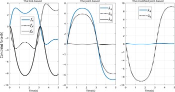
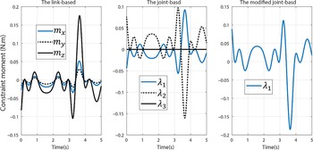
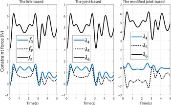
. As it is shown in Fig. 8, the input torque plots which are obtained by all three methods are compatible. Also, according to Fig. 9, for the third joint, the norm of constraint force and moment vectors are the same. The remarkable point occurred in the plot of constraint components, calculated by the three methods, which are shown in Figs.10 and 11. In fact, in the link-based method, the constraint components are calculated with respect to the reference coordinate frame, in other words,
 ${}_{}^f{\boldsymbol\lambda _i}$
and
 ${}_{}^m{\boldsymbol\lambda _i}$
are physically meaningful variables, which are constraint force and moment vectors produced in the
 ${i^{th}}$
joint. However, in both joint-based methods, these variables do not represent constraint force and moment vectors at joints in a known reference frame. Due to the full-rank CTM, in the modified joint-based, the constraint forces and moments that are along the direction of joint dofs are eliminated. As a result, in every instant, the constraint forces and moments are obtained perpendicular to the direction of joint dof; however, these components are also not reported with respect to a certain reference frame. It is noteworthy to mention that the constraint components which are obtained by the joint-based or the link-based methods cannot be related with a transformation because the reference frame in which the ones of the former are defined is not known.
The actuator torques of the spherical four-bar linkage.

The magnitude of the constraint (a) moment and (b) force vectors at the third joint (C joint).

The components of constraint moment of the third joint (C joint).

The components of the constraint force vector of the third joint (C joint).

In the case of the spherical four-bar linkage, the modified joint-based method produces a 17
 $ \times 18$
full-rank CTM. Therefore, Eq. (8) can be rewritten in the following form:
 \begin{equation}{\left[ {\begin{array}{{c}}{{{\bf{w}}_{{m_{9 \times 1}}}}}\\[4pt]{{{\bf{w}}_{{f_{9 \times 1}}}}}\end{array}} \right]_{18 \times 1}} = {\left[ {\begin{array}{{c@{\quad}c}}{{{\bf{K}}_{{{11}_{9 \times 8}}}}}&{{{\bf{K}}_{{{12}_{9 \times 9}}}}}\\[4pt]{{{\bf{K}}_{{{21}_{9 \times 8}}}}}&{{{\bf{K}}_{{{22}_{9 \times 9}}}}}\end{array}} \right]^T}_{}{\left[ {\begin{array}{{c}}{{{\boldsymbol{\lambda }}_{{m_{8 \times 1}}}}}\\[4pt]{{{\boldsymbol{\lambda }}_{{f_{9 \times 1}}}}}\end{array}} \right]_{17 \times 1}}{\rm{\;\;\;\;\;}}\end{equation}
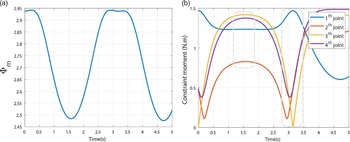
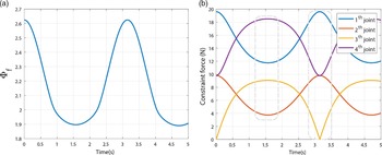
Also, the constraint moments distribution index over the prescribed trajectory is plotted in Fig. 12. In sec. 5, it was claimed that the proposed indices can represent the uniformity of the constraint forces and moments distribution on the joints. To verify the proposed claim, the norm of constraint moment vectors at all four joints of the spherical linkage is also shown in Fig. 12. As it is shown, where the index attains its maximum value (at t = 3.2s), the magnitude of constraint moments is distributed over a larger bound. However, at the minimum value of the index (at t = 1.57s), the constraint moment magnitudes are distributed in a more balanced state. Likewise, the foregoing statement can be repeated for the constraint forces distribution index and the magnitude of constraint forces, as the plots are shown in Fig. 13a and 13b.
(a) The constraint moments distribution index and (b) magnitudes of the constraint moment vectors for the spherical four-bar linkage.

(a) The constraint forces distribution index and (b) magnitudes of the constraint force vectors for the spherical four-bar linkage.

8. Case study B: the delta parallel robot
Recently, parallel manipulators are widely used in industries due to their superior speed and accuracy to serial counterparts. However, the complexity of parallel robots hinders engineers from simple and quick evaluation of their dynamic performances. To investigate the efficiency of the proposed methods on complex systems, here, the constraint wrench analysis of a Delta parallel manipulator (Fig. 14) is conducted. As it is shown in Fig. 15, each leg of the robot is composed of a parallelogram, made of four rigid links connected by four parallel-axis revolute joints. This parallelogram is connected by means of two revolute joints to the first link and the moving platform. Here, to simplify the dynamic model, it is assumed that the parallelogram is made of two longer links, which are connected by two universal joints to the adjacent links (Fig. 14). In other words, the shorter links are assumed massless, which play only a kinematical role, and hence, the kinematic chain of the robot can be considered as 3-RUU. With the foregoing modeling, and based on the notation used in Eq. (15), for this parallel robot, it yields that
 $n = 8,\;\;m = 9,\;\;{\rm{and}}\;k = 15$
, and as a result
 $\tau = 3.\;$
Therefore, the joint-based CTM,
 ${{\bf{K}}_J}$
, which is obtained by the method addressed in sec. 3 [Reference Taghvaeipour, Angeles and Lessard39], is a
 $54 \times 42$
rank-deficient matrix, while the one which is obtained by the modified version is a full-rank
 $39 \times 42$
matrix. Also, the link-based CTM is obtained as a
 $42 \times 54$
rank-deficient matrix. The constraint force and moment vectors, the joints axis, and the actuator of the
 ${i^{th}}$
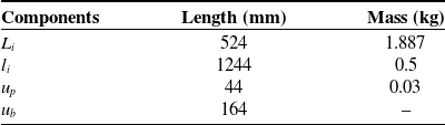
leg are shown in Fig. 15. The robot dimensions and specifications are also presented in Table I and Fig. 16.
Delta parallel manipulator.

The constraint wrenches, joints axis, and the actuator for the
 ${{\rm{i}}^{th}}$
leg, where
 ${\rm{i}} = 1,2,3$
.

The specifications of the Delta’s components [Reference Raoofian, Taghvaeipour and Kamali45].

The angles and the links dimensions for the
 ${\rm{\;}}{i^{th}}$
leg, where
 $i = 1,2,3.$

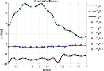
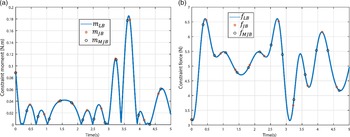
Here, the constraint wrench analysis of the robot is conducted by resorting to the link-based, joint-based, and the modified joint-based methods. In this regard, it is assumed that the robot’s MP operates over a test trajectory which is shown in Fig. 17. The actuators torque, obtained by the three methods, is shown in Fig. 18. Apparently, the three methods end up with the identical actuators torque. The magnitude of the constraint force and moment vectors at the second universal joint of the second leg is also plotted in Fig. 19(a) and Fig. 19(b), respectively. As it can be seen in Fig. 20 and Fig. 21, in contrast to the link-based method, the joint-based counterparts do not provide the components of constraint force and moment vectors with respect to a specific coordinate frame.
The trajectory of the Delta robot’s MP.

The actuator torques of the Delta robot.

The magnitude of the constraint (a) moment and (b) force vectors at the second joint (U joint) on the second leg.

The components of the constraint moment at the second joint (U joint) on the second leg.

The components of the constraint force at the second joint (U joint) on the second leg.

The CTM of the Delta robot which is obtained by the modified joint-based is a
 $39 \times 42$
full-rank matrix whose transpose maps the constraint forces and moments at joints to the constraint wrenches at the center of mass of bodies, namely,
 \begin{equation}{\left[ {\begin{array}{{c}}{{{\bf{w}}_{{m_{21 \times 1}}}}}\\{{{\bf{w}}_{{f_{21 \times 1}}}}}\end{array}} \right]_{42 \times 1}} = {\left[ {\begin{array}{{c@{\quad}c}}{{{\bf{K}}_{{{11}_{21 \times 12}}}}}&{{{\bf{K}}_{{{12}_{21 \times 27}}}}}\\{{{\bf{K}}_{{{21}_{21 \times 12}}}}}&{{{\bf{K}}_{{{22}_{21 \times 27}}}}}\end{array}} \right]^T}_{}{\left[ {\begin{array}{{c}}{{{\boldsymbol{\lambda }}_{{m_{12 \times 1}}}}}\\{{{\boldsymbol{\lambda }}_{{f_{27 \times 1}}}}}\end{array}} \right]_{39 \times 1}}{\rm{\;\;\;\;\;}}\end{equation}
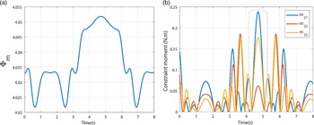
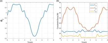
In the case of Delta parallel robot, the constraint moments distribution index is calculated and plotted over the MP trajectory of Fig. 17. As an example, the magnitude of constraint moments at the second joint (Universal) of all three legs is also presented in Fig. 22. As it is shown, at the maximum value of distribution index, the constraint moment magnitudes are distributed over a larger bound, where the peak values occur as well. However, at the minimum value of the index, the constraint moment magnitudes are distributed in a more balanced state. The correspondence between the behavior of index and the constraint force magnitudes is more visible in Fig. 23. As it is apparent, when the constraint forces distribution index is at its minimum value (at t = 4.6s), the differences between the constraint force magnitudes of the three joints will be less. In other words, the applied force distributed over the three joints in a more balanced behavior.
(a) The constraint moments distribution index and (b) magnitudes of the constraint moments for the second joints of each leg in the Delta robot.

(a) The constraint forces distribution index and (b) magnitudes of the constraint forces for the second joints of each leg in the Delta robot.

Upon comparison of Fig. 22 and Fig. 23, it reveals that the constraint moments and forces distribution indices behave in a conflicting manner. However, as it can be seen, the variation of the latter is more significant than the former, and thus, the behavior of the constraint force index can be considered pivotal in this case. Although it is observed that in the abovementioned cases the proposed indices can estimate the way that the constraint forces and moments are distributed over the joints, the authors could not conclude similar results in general cases and on all joints. Therefore, the meaning, efficiency, and application of the proposed indices call for further investigation in the future.
9. Conclusion
In this paper, two different approaches were evaluated in the constraint wrench analysis of robotic systems. The first approach, which was called the joint-based method, relied on the kinematic constraints imposed by kinematic pairs on the connected bodies, while the second one, which was referred to as the link-based method, benefited from the wrench transfer formula in rigid bodies. It was shown that both methods need to take into account zero-power relations as well. In this study, by resorting to the definition of reciprocal screws, an alternative joint-based approach was also proposed. The main difference between these methodologies comes from the way each of them composes the CTM. Thus, the properties of the CTMs, which were obtained by the three methods were discussed. Next, by resorting to the geometrical representation of the modified joint-based CTM, constraint forces and moments distribution indices were introduced. The efficiency of introduced indices still needs to be investigated, however, in a broad picture, they have been estimated to be able to reflect the uniformity of constraint forces or moments produced at kinematic pairs in a multibody system for a certain operation.
In the end, the three approaches were evaluated on two case studies, a spherical four-bar linkage and a Delta parallel manipulator. The numerical results revealed that although the actuator torques and the magnitude of the constraint moment and force vectors were obtained identically by the three methods, the joint-based approaches do not provide meaningful components with respect to a specific coordinate frame. In other words, if an analyst is looking for a methodology to accurately evaluate the constraint force and moment vectors at the joints, both in magnitude and direction with respect to a specific axes, the joint-based methods cannot be the proper candidates. Upon evaluation of the introduced indices on the case studies, it was also concluded that the indices can approximately reflect the balanced or unbalanced distribution of constraint moments and forces on the joints.