I. INTRODUCTION
The cutting process occurs when a small volume of material around the cutting edge is removed either in a continuous or intermittent cut. This cutting edge/work–piece interface determines the performance of the tool, the machinability of the material and the quality of the machined surface. During the cutting process, many events occur at the said interface that cannot be observed by the naked eye. They are tool vibration, tool wear, metal flow, and increasing temperatures, which could only be estimated through analytical and experimental methods. Wear rate is defined as the volume or mass material removed per unit time or per unit sliding distance and is a complex function of time.Reference Hutchings1 The initial period during which the wear rate changes is known as the “run-in” or “break-in” period. Wear during run-in depends on the initial material structure and properties and on surface conditions such as surface fluids.Reference Wang and Zhou2 Wear of the cutting edge is caused mainly by load, friction, and high temperature. Wear mechanism could be classified as adhesion, abrasion, diffusion, oxidation, and fatigue.Reference Liao, Lin and Wang3
Inconel 718 has the ability to maintain most of its strength even after long exposures to elevated temperatures and is the only material suitable for combustion sections of the jet engines.Reference Sharman, Hughes and Ridgway4 Therefore, it is considered to be the most difficult machine materials. Its high alloy content and high strength offers plastic deformation resistance during machining that leads to rapid work hardening. This problem occurs especially when cutting temperatures are below 650 °C, where the hardness of the material increases with increasing temperature.Reference Liao, Lin and Wang3 These conditions create the formation of sub surface residual stresses at the machined surface that further causes dimensional instability.Reference Srinivasulu and Subhash5 Its low thermal conductivity that causes high temperature is generated at the tool tip even at a low cutting speed. Good mechanical properties together with work hardening lead to an increase in cutting forceReference Liao, Lin and Wang3 and this causes many problems and leads to early tool failure. In addition, chips are easy to weld on the tool to form a build-up edge (BUE).Reference Alauddin, El Baradie and Hashmi6 Even though this nickel-based alloy contains carbide particles (CrC, TiC, MoC, WC, FeC, and NbC) as to improve the creep resistance,Reference Bradley7,Reference Krain, Sharman and Ridgway8 it consists of abrasive carbide that contributes to a reduction in the tool life.Reference Sharman, Dewes and Aspinwall9
In machining process, most of the mechanical energy used to remove materials becomes heat, which generates high temperature in the cutting region. The higher the cutting speed, the faster the heat generation and higher temperature resulted. A new challenge in machining is to use high cutting speed to increase productivity. This is the main reason for rapid tool wear. For titanium and its alloy, this problem is more severe due to their low thermal conductivity. 80% of the heat generated in the cutting region goes to the cutting tool.Reference Krain, Sharman and Ridgway8 Titanium (Ti) and titanium alloy is one of many alloy materials developed and used widely, especially in the field of aerospace, automotive, offshore industry, biomedical materials, oil exploration and nuclear tanks. Titanium alloy, classified as difficult and cost expensive in the machining process, has special properties such as unique strength to weight at high temperatures, resistant to cracking at high temperatures, decreased chemical properties, wear resistance, corrosion resistance at high temperatures, longer life and suitability with the composite structure.Reference Che-Haron and Jawaid10–Reference Jawaid, Sharif and Koksal12
Metal matrix composites have been introduced in engineering application for more than thirty years due to their superior mechanical properties such as high strength, hardness, wear resistance, and the strength to weight ratio.Reference Muthukrishnan, Murugan and Rao13–Reference Barnes, Pashby and Mok15 The replacement from the conventional material shows that this combination of a tough metallic matrix with a hard ceramic reinforcement material offers a good potential in automotive and aerospace industries.Reference Heath16,Reference Hung, Yeo and Oon17 These materials can also be used in sports and recreation facilities, boat and shipbuilding, wind energy generation for wind turbine blades, and in oil and gas offshore exploration.Reference Yang, Boom, Irion, van Heerden, Kuiper and de Wit18
The difficulty issue in machining of metal matrix composites (MMCs) is one of the major problems that are preventing its wide spread in engineering application.Reference Ding, Liew and Liu19 These composite materials are anisotropic, non-homogeneous and their hard ceramic reinforcing fibers or particles are very abrasive and make these materials difficult to form and machine.Reference Looney, Monaghan, O'Reilly and Taplin20 This resulted in the limited use of MMCs in the automotive and aerospace industries due to the higher machining cost,Reference Hung, Boey, Khor, Oh and Lee21 short cutting tool life, and bigger sizes of hard particles reinforced to the matrix material.Reference Durante, Rutelli and Rabezzana22
This paper presents the wear mechanism that caused the failure of the carbide tool which commonly occurred on the cutting edge of carbide tools in machining various materials of inconel alloy, titanium alloy and MMC.
II. METHODOLOGY
Machining experiments were conducted to study the effect of machining parameters on the wear mechanism and failure mode of carbide cutting tools in milling and turning operations. Two types of machining processes were tested, namely milling and turning processes.
A. Milling experiments
The milling experiment was performed using a DMC635V eco DMGECOLINE vertical milling machine (DMG Shanghai MT Co. Ltd., Shanghai, China) under dry cutting conditions. Two milling processes were performed to investigate the failure of carbide tools:
(i) Milling of a 160 mm × 100 mm × 50 mm block of double aging Inconel 718 using tungsten carbide with multi-layer physical vapor deposition (PVD) TiAlN/AlCrN grade ACK 300. Table I shows the chemical composition of the Inconel 718. The tungsten carbide insert was 10 mm diameter, with tool geometry of relief, radial rake, and axial rake angles of 11°, 0°, and −3°, respectively. The approach angle was 90°.
Inconel 718 composition.

The down milling operation was carried out with a cutting speed of 100–140 m/min, feed rate of 0.1–0.2 mm/tooth, axial depth of cut (DOC), ap of 0.5–1.0 mm, and radial DOC, ae of 0.2–1.8 mm.
(ii) Milling of a 100 mm × 150 mm × 50 mm block of aged treated AlSi/AlN MMC. The chemical composition of the AlSi alloy, as shown in Table II, was determined by using a glow discharge profiler (Model-Horiba Jobin Yyon, Middlesex, United Kingdom). The mean size of the reinforcement particles is <10 μm and the purity >98%. The milling test was conducted using uncoated carbide inserts of EH520, fine-grained carbide, WC–10% CO. The geometry of the insert has a positive rake angle, a lead angle of 90°, and with a nose radius of 0.2 mm.
AlSi/AlN MMC composition.

The down milling operation was performed with a cutting speed of 240–400 m/min, feed rate of 0.3–0.5 mm/tooth, axial DOC of 0.3–0.5 mm, and % of reinforcement of 10–20.
B. Turning experiments
All machining experiments were performed on a Tornado T4 CNC lathe (Colchester-Harrison, West Yorkshire, United Kingdom), with a GE Fanuc Series 21i-TB as the controller. The work piece material used in these experiments was a cylindrical bar of alpha-beta (α-β) titanium alloy Ti–6Al–4V extra-low interstitial (ELI), which consists of equiaxed α-phase surrounded by α-β phase in the grain boundary. The nominal composition of the alloy (in wt%) is given in Table III. A carbide insert with the International Standards Organization (ISO) designation of CNGG 120408-SGF-H13A was used in the machining experiments. The cutting tools used were uncoated, straight tungsten carbide chip breakers with a rhombic shape. The insert consisted of 82.6 wt% tungsten carbide and WC with 16.4 wt% cobalt, as well as Co as the binder.
Chemical compositions of Ti–6Al–4V ELI (% wt) referred by Titanium Security International (TSI) Titanium.

The experiments were performed under minimum quantity lubrication (MQL) at a rate of 50 mL/h, with air pressure 7 kgf/cm2 (bar) high velocity stream of MQL aerosol projected along the auxiliary cutting edge of the insert. The cutting speed tested was 120–220 m/min, feed rate was 0.1–0.2 mm/rev, and DOC was 0.4–0.6 mm.
C. Tool wear measurement and investigation
The tool wear measurement was done using a Mitutoyo toolmaker's microscope (Kawasaki, Japan), 30x magnifications with repeatability ±3 μm. To eliminate any influence of the previous cutting effect on a work piece, every new layer will be faced/turned using a non-test insert. The tool wear on the flank face was measured after a specific pass interval; the cutting tool would be discarded from the tool holder to observe and measure the progression of wear. The wear measurement requirement would then depend on the rate of the wear growth. The measured parameter to represent the progress of wear was the maximum tool wear VBmax. The machining was stopped when VBmax = 0.3 mm. This is according to ISO 8688-2-1989, tool life failure for end mill, and ISO: 3685, 1993 for turning. The detailed investigation of wear mechanisms were carried out using a scanning electron microscope (SEM).
III. RESULTS AND DISCUSSION
A. Wear mechanisms of coated carbide in milling of Inconel 718
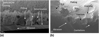
Both uniform (VB) and localised flank wear (VB3) were observed during the experiment, at the initial stage of the cutting time, the growth of flank wear rises steadily with the increase of cutting length. Figure 1(a) shows detail of the tool damage during the initial stage, which consists of abrasive wear on the flank and rake face causes a thinner coating. Sliding force of chip flow and feed force during cutter rotation causes delamination on both sides. Hence, this exposed the WC–Co base material. Further repetitive load during interrupted cutting causes pitting on the unprotected cutting edge.
Several failure modes during machining of Inconel 718. (a) Initial stage (b) steady stage.

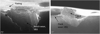
During the intermediate stage, the flank wear then grew unevenly, which could be split into VB and VBmax when notching wear appeared. The highest peak to the flank wear was formed near the DOC line, which is because of the maximum volume of material removed.Reference Kasim, Che Haron, Ghani, Sulaiman and Yazid23Figure 1(b) shows the failure mode during the intermediate stage. On the flank side, abrasion occurs severely and cavitation appears at several locations. This three-body abrasion occurs when a small carbide particle lodges between two rubbing surface, and abrades this flank surface. On the cutting edge, pitting occurs severely and then lead to the chipping, that is because of BUE formation as well as the removal process takes place aggressively. The rake face prone to flaking the TiAlN/AlCrN carbide coating was removed and then accelerated the notch wear growth. That is because of cracking and fracturing due to the cyclic load.Reference Jawaid, Koksal and Sharif24 The exposed cutting tool on these three cutting areas has deteriorated the cutting property. Figure 2 shows the tool failure mode during the catastrophic stage. The notch wear and BUE severely formed, flaking on the rake face is found to be widening, causing loss in the cutting tool edge. This phenomenon changes the tool geometry and therefore the carbide tool could not perform effectively.
Failure mode observed during catastrophic failure.

B. Wear mechanisms of uncoated carbide in milling of AlSi/AlN MMC
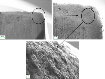
A uniform flank wear occurred at the flank face of the cutting tool as shown in Figs. 3(a)–3(c). Grooves which were observed at the flank could be seen clearly in Fig. 3(b) due to AlN particles being pulled out of the composite material and becoming dragged over the machined surface, causing scratches or grooves at the flank face of the tool. This phenomenon was similar with the grooves that were formed when Gallab and SkladReference El-Gallab and Sklad25 machined composite materials with polycrystalline diamond (PCD) cutting tool, since the wear mechanism was abrasion. Similar findings were obtained by Andrews et al.,Reference Andrewes, Feng and Lau26 which found scratches at PCD tool surface due to the adhesion between the aluminum film and diamond surface. A new aluminum covers the worn surface and then is scratched away, and these cyclic processes resulted in the progressive wear of the carbide tool. However the groove sizes are smaller due to the size of AlN particles which is less than 10 μm.
Uniform flank wear land on the cutting edge in milling AlSi/AlN MMC.

C. Wear mechanisms of coated carbide in turning of titanium alloy Ti–6Al–4V ELI
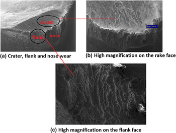
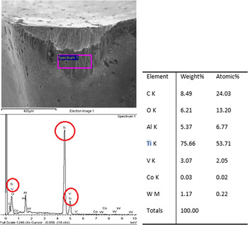
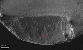
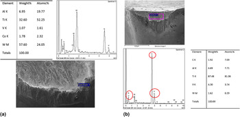
At the initial cutting process, the uniform wear on the flank face, nose and rake face were clearly seen. Further cutting caused the wear width on the nose to increase faster than that on the flank and rake faces. Flank wear, nose wear, and crater wear were formed on their respective areas as shown in Fig. 4, as well as temperature-activated wear mechanisms, in which adhesion and dissolution-diffusion became predominant. These types of wear mechanisms occurred mostly at the high cutting speed where the temperature generated exceeded the chemical dissolution temperature 1100 °C of tungsten carbide. The cutting edge of an insert is subjected to a combination of high stresses, high temperatures, and perhaps chemical reactions, which causes the tool wear due to one or several mechanisms.Reference Sulaiman, Che Haron, Ghani and Kasim27 The smooth wear on the flank face was observed underneath the adhered titanium on the flank face, as shown in Fig. 4(c). In addition, the smooth wear occurred on the flank area is due to the dissolution–diffusion wear mechanism, especially at high cutting speeds. High cutting temperatures are generated between the cutting tool and the chip during the turning operation, creating the environment for a smooth worn area. The close contact area between the tool and the chip at the higher temperature >800 °C encourages the tool material atoms to diffuse beyond the tool–chip interface.Reference Arsecularatne, Zhang and Montross28 The elements of the work piece (titanium alloy) were found on the flank face through the energy-dispersive X-ray analysis (EDAX) with the highest percentage as shown in Fig. 5. Besides through the observation, the crater wear occurred on the rake face due to the high temperature of 1300 °C recorded during the machining process, since the chemical dissolution temperature for tungsten carbide, WC, was 1100 °C. The smooth wear and the melted titanium alloy were smeared on some area of the rake face as indicated in Fig. 6. Both wear areas were analyzed through the results of the EDAX as shown in Figs. 7(a) and 7(b). Heat generated at the cutting zone, and low thermal conductivity of titanium alloy contributed to the high concentration of temperature, thus resulted in diffusion-dissolution and plastic deformation at the cutting edge.
Wear on the uncoated carbide tool edge when turning Ti–6Al–4V ELI. Flank wear, nose wear, and crater wear (a) were formed on their respective areas as shown, with high magnification of the (b) rake face and (c) flank face.

Elements identified on the flank area.

Crater wear on the top rake face of the tool; (A) smooth wear area due to the diffusion mechanism; (B) melted titanium alloy.

(a) Smooth wear area on the crater wear (diffusion mechanisms), (b) elements identified on the crater area (melted titanium alloy).

IV. CONCLUSIONS
Machining of various materials with two types of machining operations were performed to investigate the factors that affect the wear mechanism and tool failure of carbide tools. From the observation using SEM on the wear experienced on the cutting tools, it can be concluded that the tools failed primarily on two main areas of the flank and rake faces for cutting the Inconel 718, and titanium alloy. Wear such as crater, nose wear, abrasion, notching, fracturing, and cracking were observed. Whereas, in machining AlSi/AlN MMC, the tools mainly failed due to the uniform flank wear that was caused by abrasion. This finding indicated that the mode of failure for the carbide cutting tools was similar regardless of the turning or milling operations, since the failure was mainly determined by the carbide tool properties such as toughness, hardness, and brittleness properties, and the machined work piece material. Furthermore, due to the removal of the coating material, the cutting tool fails similar to that with the uncoated tool.
Supplementary Material
To view supplementary material for this article, please visit http://dx.doi.org/10.1557/jmr.2015.382.