I. INTRODUCTION
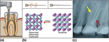
Nickel–titanium (NiTi, Nitinol) is a family of nearly equiatomic nickel–titanium, shape memory (SMA) and superelastic alloys. Because of its unique characteristics,Reference Shabalovskaya, Anderegg and Van Humbeeck1 it is being extensively used and explored for medical applications.Reference Machado and Savi2, Reference Duerig, Pelton and Stockel3 These include cardiologic, orthopedics, laparoscopic surgeries and dental applications,Reference Thompson4, Reference Walia, Brantley and Gerstein5 e.g., endodontic files (EFs) [Fig. 1(a)] used for root canal treatment. In the last decade, NiTi rotary instruments have become an important adjunct in endodontics [see Fig. 1(a)].Reference Peters6 NiTi instruments have substantially reduced the incidence of several major clinical problems in endodontics, mainly by maintaining the original shape and curvature of the canal, thus, reducing the likelihood of procedural failures.
(a) A schematic representation of an EF while shaping and cleaning the root canal. Diagram of the vector representing torque (T) when the file rotates clockwise. Vertical arrow (A) represents the direction of the apical force. (b) Structural changes following austenite-martensite stress induced phase transformation. When the file is twisted, the chemical structure transforms from austenite (cubic structure) into martensite (monoclinic). (c) Radiographic image of a tooth following file fracture during root canal treatment. The treatment of two out of three root canals has been completed successfully (red arrow), while the NiTi file fractured in the third canal, preventing the completion of the treatment (yellow arrow pointing at the fractured segment).

The major phase in rotary EFs is austenite. The stressed file transforms to the (detwinned) martensite phase. When the load on the file is removed, the NiTi file reversibly reverts to the austenite phase [Fig. 1(b)].Reference Thompson4, Reference Otsuka and Ren7 This stress-induced phase transformation results in reversible strains as high as 8% (superelasticity).Reference Thompson4, Reference Thompson and Dummer8
A common problem with NiTi devices, and EFs in particular, is their catastrophic failure [Fig. 1(c)].Reference Robertson and Ritchie9 Cyclic loadings below the yield stress lead to some irreversible long-term processes, like formation of Ni4Ti3 precipitates and defects, in the NiTi alloys (fatigue)Reference Eggeler, Hornbogen, Yawny, Heckmann and Wagner10–Reference Khalil-Allafi, Dlouhy and Eggeler12 and eventually to breakage. Indeed, occasional breakage of EFs during root canal treatment has been reported.Reference Yared, Dagher and Machtou13, Reference Parashos and Messer14 Failing to remove the fractured segment may lead to infection and loss of the treated tooth.
During the course of endodontic treatment, a repetitive stress-induced phase transformation from austenite to martensite occurs. These frequent phase changes lead to irreversible accumulation of defects and precipitates, like Ni4Ti3.Reference Khalil-Allafi, Dlouhy and Eggeler12 Since the root canal has a curved shape, flexural (compression) stress influences these irreversible changes, too. This behavior manifests itself as leading to reduced elasticity and strength of the file,Reference Sattapan, Palamara and Messer15–Reference Nayan, Buravalla and Ramamurty17 which may eventually lead to its failure.
In order for the file to go through the constricted space of the tortuous root canal [Fig. 1(a)] a combined apical force and torque are applied, advancing and spinning the file, respectively. In addition to fatigue failure, file fracture may occur due to locking of the twisted file in a constricted root canal and application of an excessive torque (termed taper-lock or incidental-failure). In this case, the applied torque exceeds the fracture strength of the file, leading thereby to immediate failure.
There are several different approaches to reducing file breakage in this research: Torque-controlled electrical motors which alert the clinician when excessive torque might be applied are in common use in endodontic treatment.Reference Peters, Peters, Schonenberger and Barbakow18 Several forms of lubricants and irrigations help reduce the file–canal surface friction, thereby reducing breakage. Surface treatments such as nitridation and ionic implantation,Reference Rapisarda, Bonaccorso, Tripi, Fragalk and Condorelli19 electropolishing,Reference Anderson, Price and Parashos20 boron and nitrogen implantationReference Pelletier, Muller, Mille and Grob21 improve the EF mechanical properties such as hardness and resistance to wear and fatigue.
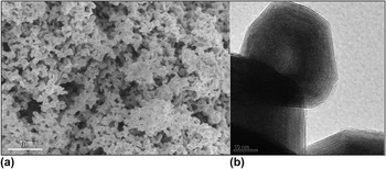
Multiwall hollow nanoparticles with nested closed cage (fullerene-like-IF) structure such as IF-WS2 and IF-MoS2 were shown to exhibit superior tribological behavior, particularly under high loads.Reference Rapoport, Bilik, Feldman, Homyonfer, Cohen and Tenne22, Reference Rapoport, Fleischer and Tenne23 Figure 2(a) shows a scanning electron microscope (SEM) image of a powder of IF-WS2 nanoparticles, while Fig. 2(b) shows a transmission electron microscopy (TEM) of one such nanoparticle. Note the concentric (nested) closed layers of WS2, which are separated 0.62 nm from each other. The quasi-spherical shape of the nanoparticles, their elasticity, and their low surface energy make them a very suitable solid lubricant.Reference Rapoport, Bilik, Feldman, Homyonfer, Cohen and Tenne22, Reference Rapoport, Fleischer and Tenne23 These nanoparticles are currently produced in various qualities and in large amounts. Different formulations are commercialized as additive to lubricating fluids by the brand-name “NanoLub.” Furthermore, metal coating impregnated with a few percents of IF nanoparticles were produced by electroless or galvanic techniques.Reference Katz, Redlich, Rapoport, Wagner and Tenne24–Reference Friedman, Eidelman, Feldman, Moshkovich, Perfiliev, Rapoport, Yoffe and Tenne26 Such coating were shown to exhibit very low friction under harsh conditions and extended testing periods and found in commercial uses.
(a) SEM image of a powder of IF-WS2 nanoparticles. (b) TEM image of a WS2 nanoparticles.

It was suggested that initially the nanoparticles roll in the constricted space between the two surfaces, and they gradually deform and exfoliate into molecular sheets that coat the metal asperities providing thereby facile shearing.Reference Joly-Pottuz, Dassenoy, Belin, Vacher, Martin and Fleischer27 Preliminary data showed no apparent toxic effect of IF- WS2 after oral administration, dermal application, and inhalation tests in rats.Reference Moore28–Reference Haist30 More recently, the viability of several kinds of human cells were tested in the presence of fullerene-like MoS2 nanoparticles, which were produced by laser ablation.Reference Wu, Yang, Song, Han, Li, Zhang, Fang, Tenne and Wang31 These studies clearly indicated that the nanoparticles had no toxic effects on cell proliferation at least up to a concentration of 3.52 mg/L. In view of the chemical similarity between MoS2 and WS2, it is likely that their toxicity is not very different. Cobalt–chromium alloys are used extensively for medical devices, including prostheses, artificial joints, heart valves, etc. Thin film electrodeposition of such alloys is also documented.Reference Dasarathy, Riley and Coble32 The biocompatibility of this alloy has been recently discussed.Reference Williams33 Thus, the exact metallic coating to serve as the matrix for the IF nanoparticles can be altered according to the specific needs.
In this work, EFs were coated with cobalt films containing a low percentage of fullerene-like WS2 nanoparticles (Co/IF). The results suggest a significant reduction of the failure rate of coated EFs in both taper-locked (incidental) and fatigue-induced modes. This analysis demonstrates that a few microns thick Co/IF coating may improve the lifetime of the root canal file and potentially also allowing it to be operated without fear of failure. Obviously, this coating does not seem to alter the mechanical properties of the underlying NiTi alloy, but rather allow it to operate under a lesser amount of stress and thereby improve its lifetime. Such coatings may, furthermore, offer an alternative to the current approach of adding lubricating agents during treatment. It is believed that this analysis bears on a large number of technologies based on NiTi SMA, where friction-induced failure is of relevance.
II. EXPERIMENTAL PROCEDURE
A. Coating procedure
An S1 Protaper EF (Dentsply, Maillefer, Ballaigues, Switzerland) was used in all experiments. The coating was performed by means of electrodeposition, using a protocol similar to that of Friedman et al.Reference Friedman, Eidelman, Feldman, Moshkovich, Perfiliev, Rapoport, Yoffe and Tenne26
The coating was evaluated using chemical and structural characterization methods: SEM model LEO-Supra 55vp (Zeiss, N. Brillerica, MA), x-ray energy dispersive spectrometry (EDS) (INCA energy, Oxford, England), and x-ray diffraction (XRD) (model D-MAX/B, Rigaku, Japan).
The adhesion of the coating was confirmed using scratch test (Nanoindenter, model XP, MTS, Agilent, Santa Clara, CA) with a spherical diamond indenter tip, at a maximum scratch load of 30 mN, scratching at a velocity of 7 μm/s.
B. Dynamic XRD
TTRAX-Rigaku test was performed using the torsion device. The XRD test was done while twisting a coated and an uncoated file. The gripping of the file was accomplished by fixing it between two stainless steel (440C) metal pieces forced with four metal springs. These four identical springs with a spring constant of 39.6 ± 2 N/mm were used for applying a measured uniaxial force on the file. The insertion length of the file d (9.1 mm) and the length of the springs L (ΔL = 3 mm) were measured by a digital caliper. The values of d and L were kept constant throughout the experiments. The file was held between the two metal plates (stainless steel 440C) partially tightened by a force of 475.2 N, provided by the four springs. To simulate the application of the torque in the root canal, the file was twisted and the torsion angle was read using a compass (100° ± 3). To minimize the experimental error, all the measurements were done sequentially in a single session.
C. Nanoindentation and fatigue evaluation
The nanoindentations (Nanoindenter, model XP, Agilent) were preceded by a preliminary in situ topographical scan at a range of 40 × 40 μm2 to evaluate the surface roughness of the specimen and precisely choose indentation locations. The EF was glued to a sample holder after cutting the handle part up until the first spiral. The indentation tests were performed 25 times on each specimen. The locations for the nanoindentation experiments were randomly distributed on the two last spirals of the file using a Berkowich tip (with a radius of curvature of about 100 nm) and a penetration depth of 350 nm.
D. Torque measurements
1. Friction evaluation (initial torque measurements)
The friction reducing effect of the Co/IF coating was evaluated using an endodontic designated torque-control motor mounted on a rig (see the schematics of the experimental set-up below). The platform was composed of a variable speed rotational motor (Dentsply, Tulsa dental, ATR Tecnika Digital Torque Control) and a torque sensor (5- CMSS 60, Eddy Probe). Generally, the speed of the motor (rpm) was chosen to be 100 rpm or less to allow sufficient time laps for data collection (except for the dynamic measurements below (next subsection), which were performed at 250 rpm and are routinely used in the clinical work). The file was held between the two metal plates (stainless steel 440C) partially tightened by a force of 475.2 N, provided by the four springs. The insertion length (d) of the file was 8.9 mm, permitting forced rotation of the file within the partially tightened metal plates. The rotating motor of the file was set to a frequency of 100 rpm.
2. Dynamic torque measurements
The same torque rig used in the initial torque test was used in this experiment. Here a PVC cube (5 mm through) with pre-drilled holes of 0.35 mm diameter was used for the drilling by the files. The rotation speed was 250 rpm and the apical movement was 0.02 mm/s.
3. Torsional incidental and fatigue-induced failure tests
The torque rig was used to test the failure of a coated file, compared to an uncoated one. The first experiment was performed using a high gripping force (633 N) and low motor frequency (80 rpm). The last 6 mm of the file’s distal end (d = 6) were held between the steel boards (stainless steel 440C). The applied load (633 N) was sufficiently high to cause separation (breakage) of the file after some measured time.
In the second experiment (fatigue-induced failure), the gripping force was lowered to 110.9 N, so that the file could rotate forward (0.2 s) and backwards (0.1 s) many times between the metal pieces before failure. The working length of the file (d) was 4.4 mm.
III. RESULTS AND DISCUSSION
A. Coating procedure
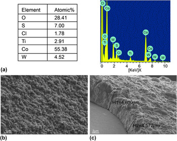
The EDS analysis and SEM images of an EF coated with a Co film impregnated with IF-WS2 nanoparticles (Co/IF) are shown in Fig. 3. The thickness of the films was found to be roughly proportional to the deposition time (about 0.8 μm/min). It appears from the EDS analysis that the coating contains typically 5–8 at.% of IF-WS2 nanoparticles.
(a) EDS analysis (20 keV beam) of the coated file. (b, c) SEM images of a file coated with Co/IF film. The coating was prepared, at a current density of 12 mAcm−2, for a period of 6 min. The nanoparticles appear as surface bulges.

The XRD pattern of coated and an uncoated EF is shown in Fig. S1 (supporting information). The XRD pattern shows that the coating process did not alter the file’s phase composition and the Ni:Ti ratio remained unchanged (51:49). Moreover, the IF-WS2 nanoparticles are omnipresent in the coating. The scratch test (Fig. S2 in the supporting information) shows an almost complete recovery after the stress has been removed, indicating good elasticity of the file and adhesivity of the coating.
B. Dynamic XRD
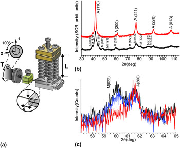
Using a custom-made torsion device [Fig. 4(a)], the XRD pattern of the NiTi file was tested while being tightly gripped by the metal supports and twisted. The torsion device was fabricated to allow measuring of the diffraction pattern of an EF while being subjected to combined rotational and loading strains. This experiment is not intended to directly simulate the rotation of the file inside the root canal, but it nonetheless serves to take into account of some of the salient features of this operation.
XRD experiment of an EF that is being strained by a combined clamping/twisting force. (a) Schematic rendering of the device used for the torsion experiments of the EF, enabling the XRD examination of the file while being clamped and twisted. L, length of the spring holding the file in place and d, insertion depth of the file between the gripping metal plates. The arrow (enlarged image) points to the place where the x-ray beam was focused. (b) The XRD pattern of the untwisted file (red curve) and the same file pattern while being twisted (black curve). (c) XRD patterns of coated (red) and uncoated (black, blue) files. The files were twisted to the same degree, and the XRD test was performed. The XRD was focused around 2 = 60° angle, where the austenite-martensite peaks are close but still distinguishable from one another.

Figure 4(b) shows the XRD pattern (wide scan) of a gripped file (red curve, see also Refs. Reference Kuhn, Tavernier and Jordan16 and Reference Bahia, Martins, Gonzalez and Buono34) and of a gripped-twisted file (black curve). The XRD pattern of the gripped untwisted file shows that it consists mainly of an austenite phase. Twisting the file while being gripped results in a phase change for most of the NiTi crystallites in the file into (detwinned) martensite (black curve). Figure 4(c) compares the XRD pattern (narrow scan) of coated and uncoated files gripped by the torsional device [Fig. 4(a)]. First, an uncoated file was tested (black), followed by the coated file (red) and a repeat test of the uncoated file (blue) to ensure that no change in the apparatus occurred between the tests. The XRD was focused around 2θ = 60° angle, where the austenite-martensite peaks are close but still distinguishable from one another.
Under gripping force (475.2 N) and 100° twist angle, the austenitic-martensitic phase transformation is clearly seen on the uncoated file [Fig. 4(c)]. In contrast, the coated file does not show this phase transformation regardless of the twisting angle. In fact, when mounting the coated file at the same gripping force (475.2 N), no phase transformation occurs, regardless of the twisting angle. These results indicate that the Co/IF coating leads to a substantial reduction in friction between the coated file and the surfaces of the metal pieces, reducing thereby the specimen tendency to go through the stress-related phase transformation. It must be emphasized at this point that these experiments were repeated many times with no observable damage to the file or the coating or its delamination from the file surface.
C. Nanoindentation and fatigue evaluation
Nanoindentation can be used as a tool for evaluating the internal stress and fatigue of a NiTi file following clinical work. Generally, NiTi presents a bimodal distribution of the elastic modulus and hardness. Crystallites consisting mostly of the martensite phase exhibit Young’s modulus between 20 and 50 GPa, while austenite domains show values of 40 to 90 GPa.Reference Liu and Yang35 The results of the mechanical measurements reported in the literature vary greatly with the specific testing conditions, applied stress, and temperature. Moreover, the volume fraction of the martensite may increase while applying stress by the nanoindenter tip, which may explain the scattering in the experimental data.
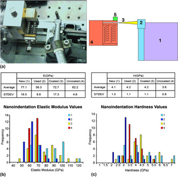
Nanoindentation was used to characterize the mechanical properties of four different EFs (samples 1 to 4). A torque rig was specially constructed to simulate the irreversible stress produced on a functional file [Fig. 5(a)]. The elastic modulus [Fig. 5(b)] and hardness (Fig. 5(c)] of file tips of two pairs were compared: a new (pristine) file (1) and a clinically used file, discarded from an endodontic practice (2); coated (3) and uncoated (4) files subjected to the same amount of work using the torque rig [Fig. 5(a)] before the nanoindentation study, were also measured.
(a) Image (left) and schematics (right) of the torque measuring platform (top view). 1, apical movement motor; 2, endodontic designated torque motor; 3, EF; 4, sample; 5, torque sensor. (b) Modulus (E) and (c) hardness (H) values obtained through nanoindentation experiments for unused (new-sky blue-1) and clinically used (blue-2) files; coated file subjected to stress using the torque platform (coated-yellow-3); uncoated file subjected to the same amount of stress as the coated one, using the torque platform (uncoated-red-4). Note that the analysis indicates that the uncoated file has suffered severe fatigue.

The new file (1-sky blue) shows a wide spread of hardness and elastic modulus values, as indicated by the relatively high standard deviations (STDV) of 1.3 and 16.5 GPa respectively. We suggest that the high spread is actually caused due to the samples being drawn from a bimodal distribution, where the two peaks indicate the martensite and austenite domains, which coexist interchangeably in the sample file. The modulus and hardness results of the used file (2-blue) are much less spread out (STDV of 9.6 and 1.1 GPa), with the average elastic modulus shifted from 77.1 to 56.3 GPa. These observations could indicate a mechanical deterioration of the used file, which is manifested as a low-stress-related transformation. Alternatively stated, these results can be attributed to fatigue-related martensite stabilization.Reference Eggeler, Hornbogen, Yawny, Heckmann and Wagner10, Reference Liu, Tan and Miyazaki36, Reference Liu and Tan37
In the next series of nanoindentation experiments, the Co/IF coated file (3-yellow) was compared to an uncoated file (4-red). Both files went through the torque measuring test [discussed below, using the rig shown in Fig. 5(a)] before the experiment and hence are believed to have suffered some fatigue. Indeed it is seen that both files exhibited reduced average modulus as compared with the unused file (1), as well as reduced hardness in the case of the uncoated file. Nevertheless, the reduction is much more significant in the uncoated file (4) as compared to the coated one (3). In addition, the elastic modulus of the coated file exhibits an STDV that is significantly larger than that of the uncoated file (17.3 versus 4.6 GPa), which may be indicative of a modest fatigue and retention of the mechanical properties of the file. Contrarily, the modulus and hardness of the uncoated file shows a single peak, at much lower values (mean modulus of 62.2 GPa), which are similar to those of the clinically used file. These results suggest that the uncoated file has suffered a greater deal of fatigue during the torque tests.
D. Torque measurements
1. Friction evaluation (initial torque measurements)
It was hypothesized that reducing the friction between the file (and also the drilling chips) with the walls of the canal will reduce the stress applied on the file and its fatigue, thereby minimizing the rate of file failures. To put this idea to the test, the initial friction of the partially gripped file was measured using a torque measuring rig [Fig. 5(a)]. The amount of applied torque required to achieve 100 rpm is directly proportional to the friction coefficient of the file, therefore, giving an indirect estimate for this parameter. Here, a Co/IF coated file was compared to the uncoated file (the friction coefficient of NiTi substrates coated with Co alone was found to be very highReference Samorodnitzky-Naveh, Redlich, Rapoport, Feldman and Tenne25 and was not studied here any further). The file was held by the two metal supports, which were not fully tightened to allow forced rotation of the file. The applied torque went down from 0.9 N∙cm in the case of the uncoated NiTi file to 0.27 N∙cm for the Co/IF coated file. These results indicate that the coating leads to a substantial reduction in the friction between the coated file and the metal support.
2. Dynamic torque measurements
In dynamic torque tests (Fig. S3), the torque applied onto a coated and an uncoated file was measured while drilling through an existing opening in a PVC substrate. In addition to the expected reduction in torque, this figure demonstrates a drastic reduction in stick-slip behavior in coated EFs, as compared to uncoated files. Stick-slip is a phenomenon that reflects the interaction of the triangularly shaped file with the walls of the hole. The absence of high frequency stick-slip phenomenon and lower torque in the case of the coated file indicates a smoother penetration of the file and consequently reduced fatigue. This is further supported by the size and shape of the drilled hole openings. The diameter of the drilled hole is found to be 10% smaller on the average for the coated as compared to the uncoated file. Furthermore, the cross-section of the pore obtained by the coated file has a circular shape as compared to a rhombohedral shape of the uncoated pore. Both the shape and diameter of the drilled canals indicate a more preservative preparation of the canal. Combined with reduced stick-slip, the ability of the file to remain concentric in the canal is improved, thereby reducing the possibility of procedural unfavorable outcomes (such as drilling in a course different from that of the natural canal).
The striation zones appear under the corners of the file’s triangular cross-section (shown below). This indicates that, as expected also from the stick-slip behavior (Fig. S3) of the uncoated file, the applied torque is not uniformly distributed on the circumference of the file. Therefore, the striations nucleate at the corners close to the file surface, where the file-canal-wall interaction is the strongest. Consequently, reducing the torque and making it more evenly distributed on the coated file surface lead to a time-delay for nucleation of the striations, which are associated with irreversible changes and fatigue.
Partial delamination of the coating from the substrate, particularly at the corners of the files, is shown in Figs. S3(b)–S3(d). In this test the torque applied is generally greater than that applied during clinical practice and is applied for a longer duration of time. Still, the coating remains mostly intact after the test. This delamination pattern suggests that the coating’s self-lubricating characteristics prevented excessive load developing on much of the NiTi file surface, other than the corners and failure zone. Nonetheless, further optimization work is needed to make this coating even more adhesive and improve its effectiveness.
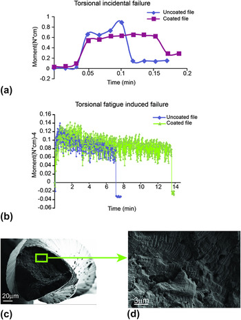
3. Torsional incidental and fatigue-induced failure tests
Figure 6 describes the files’ rotation to failure experiments, performed on the previously described platform [Fig. 5(a)]. Two different situations were tested: In Fig. 6(a), the clamping force applied on the tip was relatively high, simulating the taper lock (incidental) mode of failure. Although in this kind of test, the time to failure is relatively short, the test results show that the separation of the coated file occurred after twice as long on average as compared to the uncoated file (6 s for a coated file versus 3 s for an uncoated file). Moreover, the applied torque (maximal value of 0.88 N cm) on the uncoated file during this test was higher than that on the coated one (0.62), being consistent with the results of the friction test. These results suggest that during clinical work, the coated files could exhibit lower incidental failure probability.
(a) Incidental torsional failure test of an uncoated (blue) and coated (red) files. (b) Fatigue induced torsional failure of a coated file (green) and an uncoated (blue) file. The separation is indicated as a sudden reduction in the torque. (c, d) SEM images of the uncoated file subjected to torsional fatigue failure [Fig. 3.(b)]. On the right, enlarged image showing fatigue striation (shear bands), indicating that the breakage was related (at least in part) to fatigue

In Fig. 6(b), the clamping force holding the tip of the file was modest, and the file was rotated (almost freely) back and forth—0.20 s in forward motion and then 0.10 s in a reverse direction—until failure, leading to fatigue-related failure. This mode of failure is further evidenced by the presence of striations (shear bands due to martensite domains) on the surface of the fractured area, as seen in Figs. 6(c) and 6(d).Reference Spanaki-Voreadi, Kerezoudis and Zinelis38–Reference Brinson, Schmidt and Lammering40 The uncoated files failed after 6.3–7.2 min, while the coated files failed after 14–19 min.
IV. CONCLUSIONS
IF/Co-coated EFs experience less friction, phase transformation and mechanical deterioration as compared to their uncoated counterparts. This suggests that the coated EFs might be less susceptible to breakage under work-related strain, as occurs during treatment. In addition, the reduced friction and subsequent torque might allow the use of NiTi EFs under conditions currently considered too risky and complicated. The proposed coating may be applicable to a wide range of NiTi-based technologies and medical applications and is likely to have a favorable influence on the performance and lifetime of NiTi devices.
ACKNOWLEDGMENTS
We deeply thank R. Rosentsveig (synthesis of the IF-nanoparticles), B. Pasmantirer (technical design), G. Adini (calculations), N. Lachman (spring force measurements) for their help. We acknowledge the support of the G.M.J. Schmidt Minerva Center, the Harold Perlman Foundation, the Irving and Cherna Moskowitz Center for Nano and Bio-Nano Imaging, the Israel Science Foundation, and the ERC Grant INTIF 226639. R.T. holds the Drake Family Chair in Nanotechnology and is the director of the Helen and Martin Kimmel Center for Nanoscale Science.