I. INTRODUCTION
In the past two decades, Al–Fe–V–Si series heat-resistant aluminum alloys have received considerable attention due to their low density, excellent thermal stability, high specific strength, and high specific stiffness. Reference Skinner, Bye, Raybould and Brown1,Reference Skinner, Kim and Griffith2 These alloys have exhibited the potential to replace some of titanium alloys applied in aviation and aerospace industries at temperatures up to 673 K. Reference Li, Yu, Chai and Li3 Among them, AA8009 alloy, composed of nominally 8.5 wt% Fe, 1.3 wt% V, 1.7 wt% Si, and balance Al, is the most attractive owing to its good combinations of room and elevated temperature strengths, ductility, and toughness. Reference Frank and Hawk4,Reference Khatri, Lawley and Koczak5 Its outstanding properties are attributed to the formation of nanosized, thermally stable Al12(Fe,V)3Si dispersoids within Al matrix after appropriate rapid solidification techniques, such as planar flow casting (PFC), spray deposition, and rapid solidification/powder metallurgy. Reference Hariprasad, Sastry, Jerina and Lederich6–Reference Wang, Zhu, Xiong, Zhang, Liu and Zhang10 Nevertheless, the applied AA8009 alloy components with complex geometrical shapes are difficult and time consuming to manufacture directly via these conventional processes. Reference Seivastava, Ojha and Ranganathan11 Further consolidation by hot rolling or hot extrusion procedures is usually required, which may not meet the requirement of widespread applications.
Selective laser melting (SLM) has emerged as a promising approach to build 3D metal parts with complex structures. Reference Rolink, Vogt, Senčekova, Weisheit, Poprawe and Palm12,Reference Sercombe and Schaffer13 During the SLM process, a component is created directly from the computer-aided design (CAD) model by selectively melting successive power layers using a high energy laser beam. In comparison with conventional fabrication methods, SLM presents a series of prominent advantages, namely near-net-shape, reduced buy-to-fly ratio, a lower time-to-market, and complex part production with almost no geometric restrictions. Reference Murr, Gaytan and Ramirez14,Reference Jia and Gu15
The SLM study of aluminum alloys has recently received much attention and is still developing. Previous investigations on manufacturing aluminum alloy parts by SLM have shown that this process is more difficult to control compared with processing other metal powders such as stainless steels, Ni-based, or titanium alloys. This is mainly ascribed to the poor powder flowability, the high conductivity and reflectivity of aluminum, and the formation of oxide films on the surface of melt pools. Reference Louvis, Fox and Sutcliffe16,Reference Thijs, Kempen, Kruth and Van Humbeeck17 However, several studies have demonstrated that aluminum parts with densities surpassing 99% can be produced when using high laser powers above 200 W. Thanks to the high cooling rate (103–107 K/s) associated with the SLM process, aluminum materials with very fine microstructures and improved mechanical properties are usually achieved. Reference Brandl, Heckenberger, Holzinger and Buchbinder18–Reference Wu23 But until now, limited attention has been paid to the SLM processing of AA8009 alloy.
In this paper, the characterization of Al–8.5Fe–1.3V–1.7Si (wt%) alloy fabricated by SLM from precursor powders having the same nominal composition was described. Comprehensive characterization of the as-built samples was examined using scanning electron microscopy (SEM), electron microprobe analysis (EPMA), x-ray diffraction (XRD), and transmission electron microscopy (TEM). The chemical analysis and microhardness measurements were also performed for the SLM-produced specimens.
II. EXPERIMENTAL PROCEDURE
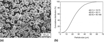
In the current study, the argon atomized (rapidly solidified), pre-alloyed AA8009 aluminum alloy powder with a nominal composition of Al–8.5Fe–1.3V–1.7Si (wt%) was utilized. Figure 1 illustrates the morphology and cumulative particle size distribution of the precursor powder, exhibiting a spherical shape [Fig. 1(a)] and particle size between 6 and 60 µm in diameter [Fig. 1(b)].
(a) Particle morphology and (b) particle size distribution of the starting AA8009 alloy powder.

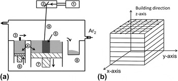
The powder was processed in an in-house developed SLM system. This SLM machine is equipped with an IPG YLR-500 Yb:YAG fiber laser, which projects a laser beam with a wave length of 1060 nm and can reach a maximum power of 500 W in a continuous mode. Figure 2 shows the SLM apparatus schematically and the scanning strategy deployed in this work. In this SLM system, the AA8009 alloy precursor powder [(4) in Fig. 2(a)] is contained in an automated powder tank indicated at (6), which feeds it onto the building part (5) on a build platform (7) (AA8009 alloy, 65 mm × 65 mm × 15 mm dimensions), where it is raked (3) into layers with a thickness of 50 µm. The laser beam (9) generated in a fiber laser source (1) is scanned across the powder layer by a CAD-driven X-Y scanner (2). Each layer was scanned twice with the same processing parameters (laser power: 350 W, scan speed: 1000 mm/s, hatching space: 0.1 mm, and layer thickness: 0.05 mm) but rotated over 90°, as depicted in Fig. 2(b). After the melting of a layer, the building platform (7) is lowered down and a new layer is raked (3). These two basic processes, power spreading and melting, are repeated, preparing an additive-layered 3D part. Excess powder is collected at (8) and recycled. To avoid alloy oxidation, the building chamber is first evacuated and then filled with an inert argon atmosphere, keeping the residual oxygen level below 0.1%.
(a) Schematic diagram of the SLM system and (b) scanning strategy applied in SLM experiments.

In this investigation, rectangular samples with a width, length, and height of 10, 10, and 15 mm, respectively, were produced. Chemical composition of the initial powder and SLM-built parts was assessed by inductively coupled plasma atomic emission spectrometry for ferrum and vanadium. Silicon was determined by photometry method, while oxygen content was measured with a LECO instrument. The relative density of the as-built components was determined using the Archimedes' method. Three SLM-built samples under the given parameters were measured and the results were averaged.
The surface morphology of the as-built parts was characterized using a JEOL 6010 SEM (JEOL Ltd., Tokyo, Japan). The as-fabricated parts were cut into sections that were perpendicular and parallel to the building direction. These sections were mounted, ground, and polished according to standard procedures. X-ray measurements were conducted on a D/Max2200 (Rigaku Corporation, Tokyo, Japan) to identify the phase composition, using a Cu target at 40 kV and 40 mA. The diffraction patterns between a 2θ angle of 20° and 90° were measured using a step size of 0.02°. Microstructures of the polished samples were examined in a JEOL 6010 SEM and a JXA-8100 electron probe microanalyzer (EPMA; JEOL Ltd., Tokyo, Japan). The specimens were also studied in a FEI Tecnai F30 TEM (300 kV; FEI Company, Hillsboro, OR) equipped with an INCA Penta FET-x3 energy dispersive spectrometry system (Oxford Instruments, Abington, UK) for elemental analysis. TEM specimen disks, with 3 mm in diameter, were cut by electric wire cutting, ground to about 200 µm in thickness, and finally thinned by ion beam milling with a Gatan 691 precision ion polishing system (Gatan Company, Pleasanton, CA) operated at a voltage of 6 kV. The Vickers microhardness was measured on the polished samples using a FM-800 microhardness tester (FUTURE-TECH CORP., Kawaski, Japan) at a load of 100 g and a dwell time of 10 s.
III. RESULTS AND DISCUSSION
A. Fabrication characteristics
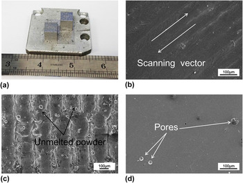
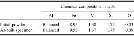
The AA8009 alloy parts can be successfully fabricated using the given processing parameters in Sec. II. Figure 3(a) illustrates the typical SLM-built test-block specimens. The density of as-built components is ∼2.90 g/cm3 in contrast to a theoretical density of 2.92 g/cm3, suggesting a quite low porosity. Table I compares the chemical composition of the precursor powder and the specimen after SLM. An important issue during the SLM process, as a result of the high melt pool temperature generated, is the evaporation of the light elements such as aluminum. However, as listed in Table I, the overall composition of the specimen is close to that of the initial powder, despite a slight evaporation of aluminum. In addition, oxidation has been considered as the main obstacle to the effective melting of aluminum alloys. The thin oxide layers on the melt pool surface may damage the bonding ability between adjacent tracks and layers. Reference Louvis, Fox and Sutcliffe16 Nevertheless, it is important to point out that the pickup of oxygen of the sample was relatively low due to the insert argon atmosphere.
(a) Optical view of the typical test components, (b) surface morphology of the component, (c) SEM image of the side edge of the part, and (d) SEM image of a polished but unetched transverse section.

Chemical composition of the precursor powder and the as-built specimen for AA8009 alloy.

Figure 3(b) demonstrates the characteristic surface morphology of the as-fabricated part. The top surface of SLM-built part shows a smooth and dense state, exhibiting no obvious open pores or thermal cracks. The scanning tracks are continuous, and sound intertrack bonding is observed. The typical balling effect associated with the SLM process was inhibited, which is an indication of good wetting characteristics of the melt pool. Reference Simchi24 Figure 3(c) illustrates the SEM image of the side edge of the as-prepared part. The columnar architecture arrays along the building direction were formed due to the incremental deposition of powder layers and the applied scanning strategy. Unmelted powder particles are evident on the surfaces of these columnar structures. Figure 3(d) shows a polished but unetched transverse section. It can be observed that the alloy powders have been completely melted, and there are few hemispherical pores (smaller than 50 µm) in the microstructure. Such build defect, which is mainly caused by the shielding gas entrapment, is comparatively common in metal products produced via SLM. Some investigations have revealed that such spherical pores are too small to affect short-term tensile properties of SLM-built parts. Reference Murr, Gaytan, Ceylan, Martinez, Martinez, Hernandez, Machado, Ramirez, Medina, Collin and Wicker25
B. Microstructural study and phase identification
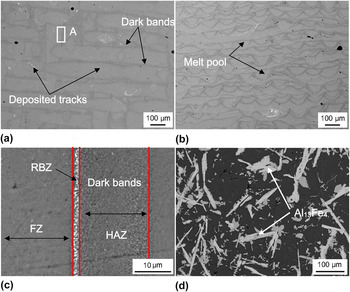
The typical SEM images of microstructures viewed along the transverse and longitudinal sections of the SLM-built part are provided in Fig. 4. In the horizontal section [Fig. 4(a)], the deposited tracks produced during the SLM process, indicated by the dark bands, are evident. The width of deposited tracks is roughly equal to the hatching distance (0.10 mm). A clear appearance of melt pools and layer superimposition can be seen in the vertical section [Fig. 4(b)]. It can be found that good intertrack and interlayer bonding with a few building defects was formed. The melt pools are approximately half-cylindrical in shape due to the irradiation by the laser power with a Gaussian profile. Similar microstructural features have been addressed in SLM processing of titanium and Inconel 718 alloys. Reference Vrancken, Thijs, Kruth and Van Humbeeck26–Reference Amato, Gaytan, Murr, Martinez, Shindo, Hernandez, Collins and Medina28 Furthermore, the size of the melt pool can be measured from Fig. 4(b). The depth of the melt pools is determined to be 60 ± 5 µm, while the melt pool width is observed to vary from 100 to 110 µm. Figure 4(c) further demonstrates that the microstructure is inhomogeneous throughout the sample, three different zones with different microstructures are typically distinguishable: laser fusion zone (FZ), remelting border zone (RBZ), and heat-affected zone (HAZ). The HAZ corresponds to the dark band in Fig. 4(a). Very fine microstructure (nearly structureless) is formed in the FZ and the HAZ, indicating a rather high cooling rate. The width of HAZ is about 10 µm, which is much narrower than that in the laser beam welded sample. Reference Whitaker and McCartney29 The RBZ, corresponding to the area where two adjacent tracks were overlapped, displays white coarsened particles. In comparison, the AA8009 alloy, prepared by the conventional casting (e.g., metal mold casting), exhibits much coarser microstructure [Fig. 4(d)] with large faceted and needle-like Al13Fe4 phase at least hundreds of times larger than the ones of the SLM deposited part.
(a) Transverse section microstructure of the SLM processed sample, (b) longitudinal section microstructure of the SLM processed sample, (c) a magnified view at location A, and (d) microstructure of the conventional casting alloy.

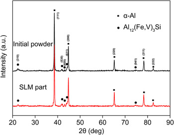
Figure 5 shows typical XRD patterns for the initial prealloyed AA8009 powder and the SLM-built parts within a wide 2θ range. It can be seen that the initial powder and the as-built components mainly consisted of α-Al solid solution and Al12(Fe,V)3Si (bcc structure). The lattice parameter, a, for the Al12(Fe,V)3Si phase was calculated using XRD data, and the average value was 1.251 nm.
XRD patterns for the precursor AA8009 alloy powder and the SLM-built part.

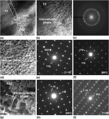
The microstructures of the as-fabricated sample were investigated in more detail utilizing TEM. Figure 6 shows TEM bright-field images (300 kV) for thin discs prepared from a transverse slice from the sample, corresponding to the SEM view in Fig. 4(a). It can be observed that the FZ exhibits ultrafine continuous supersaturated cellular α-Al networks, which grow toward the center of the melt pool [Fig. 6(a)]. Ultrafine particles are also observed in the intercellular regions of the α-Al [Fig. 6(b)]. The HAZ exhibits fine-rounded dispersoids with size between 10 and 70 nm homogeneously distributed in the α-Al matrix forms [Fig. 6(d)]. It is worth noting that, unlike the phase morphology in the HAZ, some coarser rectangle-like phase with sizes ranging from 100 to 500 nm is preferably formed in the RBZ [Fig. 6(g)].
(a) TEM micrographs showing three different zones across two adjacent melt pools; (b) ultrafine α-Al cellular networks in the FZ and (c) the SAD ring pattern of the intercellular phase; (d) fine spherical-like phase in the HAZ and (e, f) corresponding SAD patterns; (g) coarser rectangle-like precipitates in the RBZ and (h, i) corresponding SAD patterns.

A selected area diffraction (SAD) ring pattern of intercellular phase in the FZ was acquired in Fig. 6(c). The d-spacing values of the diffraction ring do not match those of the α-Al and Al12(Fe,V)3Si phases, which indicates the presence of another very fine and randomly oriented phase. The lattice structure of the intercellular phase could not be determined from the SAD analysis. It is worth mentioning that this phase might be the precursor phase of Al12(Fe,V)3Si because this intercellular phase will transform into the Al12(Fe,V)3Si phase in the subsequent heat treatment (the microstructure evolution has been addressed in another study). Qualitative EDX analysis with TEM demonstrates that the precipitates in the HAZ are enriched in Fe, V, and Si (74.8% Al, 17.2% Fe, 2.4% V, and 5.6% Si by wt%). This composition is very close to that of the Al12(Fe,V)3Si phase reported by Skinner et al. and Yaneva et al. Reference Skinner, Bye, Raybould and Brown1,Reference Skinner, Kim and Griffith2,Reference Yaneva, Kalkanlı, Petrov, Petrov, Houbaert and Kassabov30 In addition, according to the SAD patterns obtained from the spherical particles in Figs. 6(e) and 6(f), the lattice was calculated to be cubic with a = 1.258 nm. Thus, the rounded dispersoids in the HAZ are confirmed as having the lattice structure of the Al12(Fe,V)3Si phase (bcc structure) reported by Skinner et al. Reference Skinner, Bye, Raybould and Brown1,Reference Skinner, Kim and Griffith2 This result is consistent with the XRD one in Fig. 5. The size of the Al12(Fe,V)3Si dispersoids is comparable with that yielded by PFC and spray deposition approaches. Reference Skinner, Bye, Raybould and Brown1,Reference Hariprasad, Sastry, Jerina and Lederich6,Reference Hariprasad, Sastry and Jerina7 Qualitative EDX analysis reveals that the rectangle-like phase in the RBZ contains elements of 72% Al, 23% Fe, 4% V, and trace Si by wt%. The lattice structure of the rectangle-like phase, based on the SAD patterns in Figs. 6(h) and 6(i), could be determined to be tetragonal with a = 0.883 nm and c = 2.158 nm. These values are very approximate to those described by Skjerpe and Gjonnes et al. for the metastable Al m Fe phase with m = 4.0–4.4 (bct structure). Reference Skjerpe31,Reference Gjonnes, Hansen, Berg, Runde, Cheng, Gjonnes, Dorest and Gilmore32 Therefore, it is clear that the rectangle-like phase in the RBZ has the Al m Fe-type crystal structure. Such phase has also been detected in laser welding of AA8009 alloy. Reference Whitaker and McCartney29
In particular, it has been proved that the appearance of various intermetallic phases in the Al–Fe–V–Si alloy system depending on the overall alloy chemical composition as well as local cooling rates. Some studies have already been addressed on the effect of cooling rate on precipitation behaviors in AA8009 alloy. Reference Sahoo, Das and Murty33–Reference Sahoo and Pathak36 Yaneva et al. have demonstrated that an equilibrium phase Al13Fe4 is a predominant secondary phase during melt solidification at slow cooling rates, as depicted in Fig. 4(d). The Al13Fe4 phase could produce detrimental effect on the mechanical properties of the alloy due to its needle shape. Reference Yaneva, Kalkanlı, Petrov, Petrov, Houbaert and Kassabov30 With an increase of the cooling rate, various metastable intermediate phases, such as Al6Fe, Al m Fe, a-AlFeSi, etc., appeared and displaced Al13Fe4. On further increasing the cooling rate to 104 K/s or above, high volume fraction of thermal stable, strengthening Al12(Fe,V)3Si dispersoids can be formed directly from the melt. A wholly supersaturated α-Al microstructure can be obtained at a high cooling rate up to 106 K/s.
In SLM, the melting happens in layers of metal powders resulting in small melt pools that solidify rapidly, high and directional cooling rates are obtained, which can yield a unique microstructure in the as-built alloy parts. It is well-known that the thermal gradient G and the growth rate R affect the solidification behavior and microstructure fineness greatly. Reference Thijs, Kempen, Kruth and Van Humbeeck17,Reference Guan, Zhou, Li and Zheng37 The value of the thermal gradient G is calculated from the temperature variation over a certain distance (dT/dx), while the growth rate R can be given by the following equation:
 $$R = v\cos \theta \quad ,$$
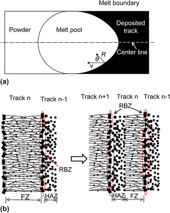
where v is the velocity of the moving laser spot, and θ is the angle between the normal to the solidification front and the laser scanning direction, as shown in Fig. 7(a).
(a) Solidification behavior of the melt pool in the case of SLM and (b) schematic illustration of the formation of three different zones in the SLM-built sample.

The G over R controls the solidification mode of the melt. From high to low, a planar, cellular, columnar dendritic, and equiaxed structure is consecutively obtained. The multiplication of G and R, which equals the cooling rate, determines the phase composition and size of the structure. The thermal gradients and growth rates change across the melt pool with the movement of the laser beam. G and R are at their peak at the centerline of the melt pool and decrease when going toward the boundary of the pool. Reference Thijs, Kempen, Kruth and Van Humbeeck17 Therefore, the solidification behavior, cooling rate, and resulting microstructure size vary due to the change in G and R.
The formation mechanism of different microstructures is schematically illustrated in Fig. 7(b). When track N deposits, the growth rate is rather low and even reaches zero at the boundary of the melt pool. Under these conditions, a low cooling rate and reduced undercooling are achieved, which enables the formation of coarsened precipitates, like the appearance of Al m Fe phase in the RBZ. Whitaker and McCartney revealed the precipitation of Al m Fe particles during laser welding of AA8009 alloy, and the cooling rate in the melt was estimated to be 1800 K/s. Reference Whitaker and McCartney29 Hariprasad et al. also reported a coarser micrometer phase at cooling rates around 2500 K/s in atomized melt deposition (AMD) process. Reference Hariprasad, Sastry, Jerina and Lederich6 Besides, the needle-like equilibrium Al13Fe4 phase is not observed in the as-built sample. Hence, it is reasonable to predict that the cooling rate at the melt border is at an order of 103 K/s. It is also worth noting that the Al m Fe phase in RBZ may not damage the mechanical properties due to its small size and favorable rectangular-shaped form. Moving from the RBZ to the FZ, G and R both increase. The cooling rate then increases significantly in the FZ, which contributes the formation of the supersaturated α-Al networks. As depicted in Fig. 6(a), α-Al nucleates on the primary Al m Fe phase and grows with a cellular morphology into the center of the melt pool. No significant change in the structure morphology is found in the FZ because G and R increase in a similar way, and G/R keeps nearly constant reported in the previous literature. Reference Thijs, Kempen, Kruth and Van Humbeeck17,Reference Guan, Zhou, Li and Zheng37 The intercellular phase particles could form as a result of solute rejection from the growing α-Al. Due to the high growth velocity of α-Al, the limited alloy melt in the intercellular regions can restrict the further growth of the phase particles. In addition, it is evident from Fig. 6(b) that the α-Al cell spacing becomes smaller when going toward the center of the pool. This indicates that the cooling rate, which determines the fineness of the microstructure, increases from the edge to the centerline of the melt pool. As track N + 1 deposits, similar solidification behavior can be obtained for track N + 1. However, part of track N is reheated to some extent again and the structures of α-Al and Al12(Fe,V)3Si form in the HAZ of track N.
C. Microhardness
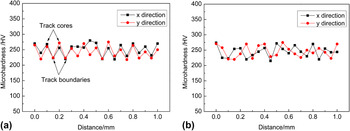
SLM components are fabricated through the overlapping of multiple tracks and layers. This additive process produces boundaries between adjacent tracks and neighboring layers, as depicted in Fig. 4. These boundaries, corresponding to the RBZs, are usually considered as the weak areas in terms of mechanical performance and may cause inhomogeneity on the mechanical properties of SLM parts. Reference Wen, Li, Wei, Yan, Zhang and Shi38 To evaluate the homogeneity of mechanical properties, microhardness measurements were carried out in x, y directions on the transverse and vertical sections of the samples.
Figure 8 shows the typical microhardness profiles. It can be observed that although the hardness curves present some fluctuation in x, y directions on both sections, the hardness variations are relative small. The hardness at the track cores is a little higher than that at the boundaries. This hardness difference can be presumably attributed to the presence of the larger rectangle-like phase in the RBZ. In addition, thanks to the rapid solidification and ultrafine microstructure in the as-prepared specimen, the average microhardness reaches 246 HV0.1, which is much higher than the values of the AA8009 material prepared by other conventional methods. Reference Yaneva, Kalkanlı, Petrov, Petrov, Houbaert and Kassabov30,Reference He, Qiao, Wang, Yang, Xu, Chen and Chen39
Microhardness profiles of SLM-built samples on the (a) transverse section and (b) vertical section.

IV. CONCLUSION
The current study described the characterization of AA8009 (Al–8.5Fe–1.3V–1.7–Si by wt%) alloy parts fabricated by SLM. The following conclusions can be drawn.
-
(1) Nearly full dense components (relative density >99%) with a few build defects have been obtained under the given processing parameters.
-
(2) The chemical composition of the SLM part is similar to that of the precursor powder despite a slight aluminum loss and a low oxygen pickup.
-
(3) Three distinguished zones are observed in the sample: the laser FZ, the RBZ, and the HAZ. Ultrafine continuous cellular α-Al networks growing toward the center of the melt pool are observed in the FZ. Ultrafine intercellular phase is observed in the cellular α-Al. The HAZ exhibits fine rounded Al12(Fe,V)3Si particles (10–70 nm) distributed homogeneously in the α-Al matrix, while the rectangle-like Al m Fe-type phase (m = 4.0–4.4) with 100–500 nm in size is preferably formed in the RBZ.
-
(4) The prepared fully dense AA8009 part presents no large microhardness fluctuation along the lateral and vertical directions and has a mean value of 246 HV0.1. The hardness at the track cores is a little higher than that at the track boundaries.
ACKNOWLEDGMENT
The authors gratefully acknowledge the financial support by the National High-Tech Program (863) of PR China (Project no. 21100002013101006).