1. Introduction
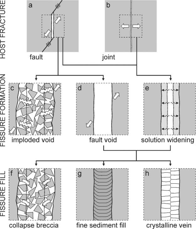
This paper is concerned with the origin and infill of large fissures or voids, decimetres to metres in aperture, that can form along or around faults in the upper few kilometres of the crust. These fissures form in two ways, which are not mutually exclusive (Fig. 1). Firstly, displacement along a fault can produce voids because the slip is on an irregular fault plane or varies along the fault plane (Fig. 1a) (e.g. Hulin, Reference Hulin1929; Newhouse, Reference Newhouse1940). These dilational sites can either implode instantaneously (Fig. 1c) (e.g. Phillips, Reference Phillips1972; Sibson, Reference Sibson1987) or, if the fault walls are strong enough, remain open as gaping fissures (Fig. 1d) (e.g. Park & MacDiarmid, Reference Park and MacDiarmid1975; Ferrill & Morris, Reference Ferrill and Morris2003). Secondly, solution along faults or joints can create fissures in limestones or other susceptible lithologies (Fig. 1e). Solution fissures can enlarge and coalesce into palaeocave systems, which are the subject of a large literature (e.g. Loucks, Reference Loucks1999). Because most of the structures in this paper are planar, the term ‘fissure’ is used here in preference to the less specific term ‘void’, but with no implication that the fissure was necessarily open to the contemporary land surface.
Mechanisms for forming (a–e) and filling (f–h) fault-related fissures. See text for explanation.

Large fissures produced by any combination of slip or solution processes can fill in a variety of ways (Fig. 1f–h), again not mutually exclusive. The walls or roof of the fissure can disaggregate to produce a chaotic breccia (Fig. 1f), more or less exotic sediment can settle into, or be injected into, the fissure to form a bedded fill (Fig. 1g), or minerals can crystallize from solution to produce a vein (Fig. 1h). Vein fills are the best described in the literature, because they often host economic minerals (Evans, Reference Evans1993; Oliver & Bons, Reference Oliver and Bons2001). Collapse-breccia fills are receiving increasing attention (Koša et al. Reference Koša, Hunt, Fitchen, Bockel-Rebelle, Roberts, Ahr, Harris, Morgan and Somerville2003; Woodcock, Omma & Dickson, Reference Woodcock, Omma and Dickson2006). Finer sediment fills are usually described from fissures open to the contemporary land surface, typically in karst terrains (Ford & Williams, Reference Ford and Williams1989; Wall & Jenkyns, Reference Wall and Jenkyns2004). It may be difficult to diagnose the formation mechanism of a fissure after any of these infill processes.
Here we report well-exposed examples of infilled limestone-hosted fissures, which we interpret as having formed mainly by fault-induced volume changes rather than by solution. First, we document the evidence that these fissures remained open after formation rather than imploding instantaneously. Then we explain the field relationships that suggest that the infill of the fissures occurred during, rather than after, active faulting. The examples provide a case study for comparison with other areas. Fissures along faults are generally important in enhancing permeability to the flow of fluids, which might include, for instance, hydrocarbons, mineralizing solutions, potable water or industrial effluent.
2. Geological setting of the Gower faults
The study area lies on the south coast of the Gower (or Gŵyr) Peninsula in South Wales (Fig. 2). The peninsula comprises Devonian and Carboniferous rocks, moderately deformed during the Variscan Orogeny in late Carboniferous time. The fissure fills all occur in the Dinantian (Lower Carboniferous) limestone-dominated part of the succession. The limestone units are typically thinly to thickly bedded bioclastic or oolitic grainstones and packstones. Some units have thin mudstone interbeds. The Variscan deformation comprises three main components (Figs 2, 3): (a) upright open folds, now plunging gently to the E or ESE; (b) thrust faults striking E to ESE; (c) steep cross-faults, typically striking between NNW and NNE. The field evidence from a number of previous studies suggests that these structures formed in an overlapping time sequence as follows.
(1) The folds formed in response to approximately NNE-directed Variscan shortening (George, Reference George1940). Minor ductile shear zones in Dinantian limestones are thought to have formed during this early folding (Srivastava, Lisle & Vandyke, Reference Srivastava, Lisle and Vandyke1995). Conjugate shear zones suggest a thrust regime (σ3 vertical) with the maximum stress direction σ1 between NNE and N (Fig. 3). Stylolite seams in limestones developed perpendicular to the shortening direction (Roberts, Reference Roberts1979).
(2) Thrusts then formed (Fig. 3), striking parallel to folds. The thrusts mostly conform to the regional top-to-the-N vergence, though the Port Eynon thrust (Fig. 2) is a NNE-dipping backthrust. Measured minor thrusts record transport directions within 20° of north (Roberts, Reference Roberts1979).
(3) The cross-faults then developed (Fig. 3), some with strike-slip or oblique-slip slickenfibre lineations (George, Reference George1940; Roberts, Reference Roberts1979). In eastern Gower, where the faults occur in conjugate sets, they indicate a broadly N–S maximum stress, σ1. The contrasts in fold style across some of these faults suggest that folds continued to grow during faulting (George, Reference George1940). Minor brittle–ductile shear zones provide additional evidence of the switch to a wrench regime (σ2 vertical), with a maximum stress direction σ1 that is NNE in eastern Gower (Srivastava, Lisle & Vandyke, Reference Srivastava, Lisle and Vandyke1995), and N further west (Roberts, Reference Roberts1979). Conjugate joint systems indicating a N–S σ1 are thought also to date from this wrench phase (Roberts, Reference Roberts1979).
(4) The wide vein-, breccia- or sediment-filled fissures (Fig. 3), which are the main subject of this paper, develop at a late stage in the kinematic history, as indicated by cross-cutting relationships (Roberts, Reference Roberts1979). The fissures mostly strike between 170° and 220° (Fig. 2), and apparently follow cross-faults (George, Reference George1940; Roberts, Reference Roberts1979). The extent to which slip on the cross-faults was still continuing during fissure formation is a focus of the present paper.
Geological map of Gower, with locations of studied fault fissures. Compiled from the British Geological Survey 1:50 000 maps (British Geological Survey, 1977, 2002), with fault names from George (Reference George1940).

Schematic block diagram of the main structural elements of the Gower Peninsula. See text for commentary.

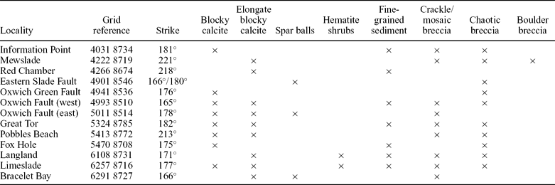
Numerous fissure fills are exposed along the cross-faults on the south Gower coast. The eleven localities referred to in this paper (Fig. 2, Table 1) are the most instructive of those safely accessible. These zones are mostly sub-vertical, with strikes varying from 165° to 221°. The fault zones containing the fissures have widths from 2 to 25 m, though the aperture of any open void was less than this.
Location, characteristics and fill components of the fault fissure examples cited in the text

3. Lithological components of the Gower cross-fault zones
Eight main lithological components are distinguished within the studied fault zones. Apart from the boulder breccia lithology, each of the components is present in a number of different fault zones (Table 1). The eight components will be described in this section, and the extent to which they evidence former voids will be assessed. Then the organization and relative timing of these lithologies within the fault zones will be described in Section 4.
3.a. Crackle and mosaic breccia
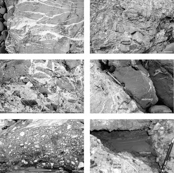
The least evolved of the various fault rocks are crackle and mosaic breccias (Fig. 4a), terms which have recently been redefined and quantified (Mort & Woodcock, Reference Mort and Woodcock2008; Woodcock & Mort, Reference Woodcock and Mort2008). In crackle breccia, the limestone protolith is pervaded by a network of fine fractures, but the resulting fragments are hardly displaced. In mosaic breccia, the fragments are separated and rotated, but not so much that they lose their fitted-fabric texture. Both breccia types normally have calcite cement between the clasts. Crackle and mosaic breccias record the early stages of brittle fragmentation in the studied fault zones. They imply some limited dilation within the zones, but no open void space wider than the aperture of individual inter-clast fractures.
The main types of fault rock or clastic fissure fill: (a) crackle and mosaic breccia, Oxwich Fault west; (b) calcite cemented chaotic breccia, Eastern Slade Fault; (c) matrix-rich chaotic breccia, Oxwich Fault west; (d) boulder breccia, Mewslade; (e) laminated fine sediment fissure fill, Limeslade; (f) laminated fine sediment fill to intraclast void, Mewslade.

3.b. Chaotic breccia
Chaotic breccia (Fig. 4b, c) comprises predominantly coarse (> 2 mm) fragments that have been displaced and rotated enough to lose any fit to their former neighbours. Clast size is typically in the range 10–100 mm. Commonly, as in the figured examples, several contrasting clast types may be present, the result of derivation from more than one protolith. Chaotic breccia can have a calcite cement (Fig. 4b) or a fine sediment matrix (Fig. 4c). It occupies fault-parallel zones with widths from 0.1 to 5 m. Chaotic breccia can form either by the normal range of fault-related brittle fragmentation processes (e.g. Sibson, Reference Sibson1986) or by later ‘sedimentary’ infill of an open fissure along a fault (Woodcock, Omma & Dickson, Reference Woodcock, Omma and Dickson2006). The distinction of these two possibilities from the breccia lithology alone is rarely possible, and even the structural context of the breccia within the fault zone may prove inconclusive. The width of ‘sedimentary’ fissure infill would indicate the aperture of the host void.
3.c. Boulder breccia
At one locality, Mewslade, a 30 m wide fault zone contains a breccia with conspicuously large clast sizes, typically greater than 20 cm and ranging up to metres in longest dimension (Fig. 4d). The larger clasts have a slab-like shape, and are clearly fragments of the thick-bedded limestones through which the fault zone cuts. These fragments are now detached and rotated, but with little preferred orientation (Section 4.d). The resulting breccia has a very open texture, with any fine-grained matrix insufficient to fill the voids between the bedding slabs. Calcite cement and fine-grained red sediment fill the remaining void space. This open texture implies substantial dilation within the fault zone during breccia formation, and a locally transtensional setting. Progressive inward collapse of the fault walls is envisaged during successive slip increments. The aperture of any fault fissures at any one time is uncertain, but would have been only a fraction of the fault zone width.
3.d. Fine sediment
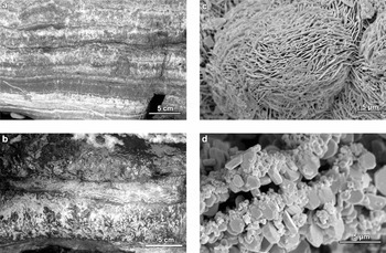
Fine (< 2 mm) sediment is commonly found as laminated infill to former void space in the fault zones. The sediment is typically reddish or orange-brown due to its hematite or limonite content, and is most commonly of fine sand or silt grade but sometimes finer. The most diagnostic geometry is for steeply dipping fissures to contain sub-horizontal, catenary-laminated sediment (Fig. 4e). These fissures are typically tens of centimetres wide, but exceptionally (at Red Chamber) reach a width of several metres. Similar fill can also occupy void space between breccia clasts (Fig. 4f). In these two settings, it is clear that sediment was deposited lamina by lamina upwards from the floor of each void. A third apparent setting of ferruginous sediment is interlaminated with crystalline calcite or dolomite (Fig. 5a). However, in most such examples, the lamination parallels steeply dipping fissure walls and cannot record gravitational settling of sediment. Microscopic evidence, discussed in the next section, suggests that most such ‘sediment’ layers are actually hematite precipitates on fissure walls. However, transitional geometries from crystalline to sedimentary lamination suggest that precipitated hematite was easily detached from fissure walls to form a major component of the bedded fine sediments. Fine hematitic sediment also forms the matrix to many of the chaotic breccia deposits (Fig. 4c). The matrix sediment is massive or weakly laminated and typically reddish-brown, but can be orange-brown. This colour variation is probably due to the presence of a proportion of limonite. This compositional factor has not been fully investigated, and the mention of hematite in this paper should be taken to include the possibility of significant limonite content also.
Microcrystalline hematite growths, all from Limeslade: (a) interlaminated hematite and calcite (lamination is vertically dipping); (b) branching hematite shrubs interspersed with calcite (lamination is vertically dipping); (c) SEM image of spheres of hematite platelets; (d) SEM image of layers of hematite platelets originally interlaminated with carbonate.

Thin-sections show that the fine sediments contain either quartz or dolomite grains as well as hematite. Dolomite rhombs, like the hematite, were probably formed as precipitates on fissure walls. The quartz grains, found in fills at Mewslade, Red Chamber, and Oxwich Fault and Great Tor, have no obvious source within the fault zones or host rock, and might indicate a connection of some fissures with the contemporary land surface. However, the general interpretation of the sediment fill as Triassic material infiltrated from the surface (Strahan, Reference Strahan1907) is unsupported. No Triassic fossils have been found in either the Gower fissures or indeed the one supposed patch of unconformably overlying ‘Triassic’ sediment on the peninsula (British Geological Survey, 2002). An attempt to extract microfossils in carbonate-free residues from the quartz-rich localities in the present study proved negative.
The bedded fine sediment fills are unequivocal evidence of open voids along the Gower faults with aperture of tens of centimetres or, rarely, several metres.
3.e. Micro-crystalline hematite
Hematite is an abundant component of the fissure fills, not only as fine sediment, but as primary precipitates. Samples of this material from Limeslade were analysed using X-ray diffraction, magnetic susceptibility tests and EDS analysis, and proved to be almost pure hematite. In thin-section the hematite appears to form singly or in aggregates of grains, each grain about 100 to 200 μm across, but sometimes the hematite has grown in branching shrubs up to 5 cm long, easily visible in the field (Fig. 5b). Scanning electron microscope observations of the microstructure, however, show that all these forms are composed of much smaller elements, typically platelets about 10 to 20 μm in diameter. The ‘grains’ visible in thin-section are spherical aggregates of radiating platelets (Fig. 5c), and fine lamination in hematite resolves as layers of platelets, originally interlaminated with carbonate minerals (Fig. 5d).
The evidence is that hematite was able to precipitate in abundance from fluids passing through the Gower fault zones. This source of hematite is sufficient to explain its secondary occurrence in fine sediment in the fissure fills, without invoking an exotic supply from the contemporary land surface. The large branching hematite shrubs evidently grew into fluid-filled voids at least 5 cm wide. The shrubs resemble the problematical Frutexites, formed by ferro-manganese hydroxides in deep-water stromatolites (Bohm & Brachert, Reference Bohm and Brachert1993) and hot-water travertines (Chafetz et al. Reference Chafetz, Akdim, Julia and Reid1998). Debated origins include bacterially induced precipitation, replacement of organic structures and inorganic chemical processes, a debate which is beyond the remit of the present paper.
3.f. Blocky calcite
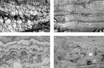
Blocky calcite occurs as masses of equant crystals, each typically 1 to 5 cm in size, with no preferred orientation that is obvious in the field (Fig. 6a). The blocky calcite is typically white, but an orange weathering variety is also common. Despite its equant habit, blocky calcite has commonly grown inwards from the edge of a fissure or irregular void into its centre, with euhedral crystal terminations showing that growth occurred into a fluid-filled space. Calcite masses up to several metres across indicate the aperture of some of the void space involved.
Calcite fissure fills: (a) blocky calcite, Mewslade; (b) elongate blocky calcite, Oxwich Fault east; (c) elongate blocky calcite, Limeslade; (d) spar balls, Oxwich Fault east.

Equant, rather than elongate, crystal growth tends to occur when there is ongoing nucleation of new crystals during growth. Such nucleation is associated with high supersaturation of the host fluid (Oliver & Bons, Reference Oliver and Bons2001). Supersaturation can arise by mechanisms such as arrest of a rapidly rising mass of fluid (Bons, Reference Bons2001) or a rapid drop in fluid pressure during hydraulic fracture (Phillips, Reference Phillips1972).
3.g. Elongate blocky calcite
A conspicuous feature of some of the calcite in the Gower fissures is a growth banding broadly parallel to the fissure wall (Fig. 6b, c). In coarser examples of this texture (Fig. 6b), the banding picks out successive well-formed growth faces of individual calcite crystals. Each crystal is elongated in the dominant growth direction, perpendicular to the fissure wall. The width of individual crystals varies from a few millimetres (Fig. 6c) to as much as 50 mm (Fig. 6b). Length-to-width ratios of crystals can be over 20 in the fine-grained examples. The maximum observed cross-fissure width of a growth-banded calcite fill is about 6 m (West Oxwich Fault), though individual crystals do not extend fully across the half-width of such a fissure. Some fills show an approximate symmetry in the banding pattern on either side of their mid-line, showing that they grew inwards synchronously in response to changing properties of a shared fluid in the centre of the void.
The calcite growth banding is picked out by hematite, which varies in nature from faint diffuse red staining of calcite to concentrated discrete films and layers of hematite crystallites, originally black and weathering reddish-brown. In places, what appears to be hematitic sediment fills gaps between calcite crystals. However, because most fissure walls are steep, gravitational settling onto them is unlikely, unless sediment was arrested above a calcite crystal growing up from below the plane of section.
Elongate blocky textures are generally interpreted in terms of competitive crystal growth normal to the substrate (Oliver & Bons, Reference Oliver and Bons2001). Such competition implies a lower nucleation rate of new seed crystals than for the equant blocky calcite, and therefore a lower degree of supersaturation of the depositing fluid. However, new calcite seeds could still grow in some situations. Where a hematite film is thick, for whatever reason, it often inhibited the growth of large calcite crystals and required the nucleation of new calcite seeds (Fig. 6b, arrowed horizon). These small randomly oriented calcite crystals reduce in number and increase in size outward, as competitive growth favours well-oriented grains (Dickson, Reference Dickson1993; Oliver & Bons, Reference Oliver and Bons2001).
The well-defined growth faces visible on the larger crystals show that they grew into a wide fluid-filled void space rather than by an incremental crack–seal mechanism. If voids were continually sealed and refractured, some reactivation surfaces would be expected to cut across large crystals, rather than precisely follow their growth faces. No such evidence is seen. It is difficult to escape the conclusion that some of the open fissures along the Gower faults were metres wide.
3.h. Spar balls
The tendency of elongate blocky calcite to grow normal to the surface on which it seeds means that crystals can form aggregates that radiate from angular corners of wall rock or from clasts in a breccia. The most puzzling manifestation of this radiating structure is in spar balls or cockade breccias (Fig. 6d). Here, breccia fragments appear completely surrounded by radiating calcite, the associated growth banding running concentrically to the spar ball. The mechanism by which seed clasts can become completely supported by cement is uncertain, and beyond the remit of the present study. Possible formation mechanisms involve successive rotation of each ball, to allow growth of the calcite on all surfaces of the ball (Genna et al. Reference Genna, Jébrak, Marcoux and Milési1996). Whether such rotation occurs by rolling or by suspension in an upward-flowing fluid, the mechanism implies an open void.
3.i. Polyphase fills
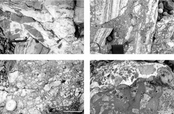
The next section will present map-scale evidence for polyphase opening and filling events in the Gower fault zones. Such a history can also be deduced from individual lithologies (Fig. 7). An example is where fragments of the fine sediment fill are incorporated in a mosaic breccia or chaotic breccia, cemented by calcite (Fig. 7a). The inverse relationship is also common, with clasts of blocky calcite incorporated into a chaotic breccia with sediment matrix (Fig. 7b, c). Where the original calcite was elongate and growth banded, the evidence is particularly clear that it grew into an open fissure, and was subsequently fragmented and mixed with sediment (Fig. 7b). A further variant is where one void-filling breccia, such as the matrix-rich chaotic breccia in the lower half of Figure 7d, is refragmented and incorporated as clasts in another breccia, here cemented by calcite. Such examples all suggest that a void-filling event was succeeded by further brittle failure, most probably due to ongoing faulting.
Polyphase fissure fills: (a) breccia of red sediment clasts in calcite cement, Information Point; (b) breccia of blocky calcite in red sediment matrix, Oxwich Fault west; (c) breccia of banded elongate calcite in red sediment matrix, Oxwich Fault west; (d) breccia of limestone in red sediment matrix, rebrecciated then cemented by calcite, Oxwich Fault east.

4. Fault zone architecture
The lithological components outlined in the previous section are arranged in a variety of ways within the Gower fault zones, and there is no one simple displacement and fill history for these zones. This section therefore describes four examples that span the range of fault zone architecture. Two common themes emerge from the detailed descriptions. First, all the zones show evidence for substantial fissures, some that might have only been transient, but most that stayed open after their formation. Second, most zones show evidence for repeated episodes of fissure formation and fill, with geometries that strongly suggest tectonic dilation due to faulting rather than solution widening.
There is some ambiguity in the kinematic interpretation of each zone. The descriptions below give the simplest interpretation in each case. The tentative sequence of fills is numbered on the fault zone maps (Figs 8, 9, 10) and keyed to the text descriptions.


4.a. Oxwich Fault east
The eastern strand of the Oxwich fault zone hosts a 10–15 m fill of breccia and vein calcite (Fig. 8a). The earliest products are probably the mosaic breccias along the eastern edge of the zone (1), a matching remnant of mosaic breccia now 10 m to the west, and crackle breccia at the western margin of the zone (2), all presumably formed during slip on the fault. The breccias were cemented, and then a fissure several metres wide opened through them. Elongate blocky calcite (3) grew inwards off the mosaic breccias into this fissure (Fig. 6b), although the eastward growth zone has later been mostly brecciated. This fragmentation happened in a weakly cross-cutting zone containing chaotic breccia with a sediment matrix (4). The presence of this matrix, together with clasts of red sediment as well as limestone and calcite, precludes an origin simply as an attritional fault breccia derived from local wall rock. The breccia is probably a sedimentary or collapse breccia sourced partly from higher levels of the fault zone. In this case, the fissure was 2–4 m wide. A zone of spar balls (Fig. 6d) within the north end of breccia zone requires a later open fissure tens of centimetres wide. The final phase of dilation produced space for a 30 cm calcite vein (5) with residual central voids filled by fine sediment.
4.b. Limeslade
The fault zone at Limeslade is only 2–3 m wide, but shows some complexity (Fig. 8b). An early brecciation event along the fault produced the crackle breccia and detached wall-rock blocks at the eastern margin of the zone (1). A fissure, tens of centimetres wide, opened during or after this event. Elongate finely growth-banded calcite (Fig. 6c) grew normal to the irregular eastern wall (2). This calcite veining was further faulted to truncate the growth banding and produce voids that were filled with red sediment (3), now commonly contorted. A fissure filled with this sediment (Fig. 4e) is also preserved against the northern part of the western wall. A fissure nearly a metre wide then opened, and elongate calcite grew inwards from both walls (4). Incomplete fill or further dilation then allowed room for growth of 5 cm long hematite shrubs interspersed with calcite (5). Only the western side of this hematite fill is preserved, with the eastern side later brecciated and further cemented by calcite (6). Finally, a new 15 cm wide fissure formed (7) and was filled by hematite shrubs and calcite growing in from both walls (Fig. 5b).
4.c. Oxwich Fault west
The western branch of the Oxwich Fault shows a 10–20 m wide NNW-striking zone of crackle breccia and elongate calcite fill, partly cut by a narrower NE-striking fault zone containing mosaic breccias (Fig. 9). The earliest events occurred in a complex volume north of the intersection of the two fault zones (Fig. 9, lower right). Early displacement on the NNW-striking fault yielded slivers of limestone only partly attached to the fault walls (1) and bordered by voids. Elongate blocky calcite grew into the voids, normal to walls and also to the slivers, producing radiating ‘cockade’ geometries around sliver terminations (2). Crystalline hematite records growth bands in the calcite, and fine red sediment fills in gaps between some large crystals. Only local sectors of the calcite in this zone appear oriented, but this lack of alignment may be because calcite grew upwards from a floor to the void not far below exposure level. Rebrecciation of the western part of the calcite fissure fill resulted in clasts of banded calcite in a matrix of red sediment (3), and a similar brecciation occurs locally at the eastern edge of the fissure fill (4) (Fig. 7c).
The NE-striking fault zone then cuts the southern end of the early fissure fill. Calcite-veined fault strands define a zone of mosaic breccia with limestone clasts set in a calcite cement (5). The NE-striking fault is in turn cut by the main NNW strands, which hosted a 5–7 m wide zone (6) of limestone crackle breccia (Fig. 4a). The main fissure opened along a 5–7 m wide zone through these crackle breccias, and was filled in by growth-banded elongate calcite growing fairly symmetrically from each wall (7). The growth banding is truncated along part of the western margin (8) by a late fault. This fault may continue northward into a splay that hosts a 30 cm wide zone of breccia (Fig. 4b) and spar balls (9).
The western Oxwich Fault therefore shows evidence for at least five separate episodes of faulting, with two intervening times when persistent fissures were filled by elongate calcite growth.
4.d. Mewslade
The fault zone at Mewslade strikes northeast and is about 30–40 m wide (Fig. 10a). Along its southeastern margin are lithologies that match those in other fault zones: crackle breccias (2) and a 3 m wide fissure filled by elongate calcite growth (1). However, both these components are truncated by the main fault zone fill, which comprises chaotic boulder breccia (3) (Fig. 4c). The breccia fragments are slabs of bedded limestone that match surrounding wall rock and, in places, are almost structurally continuous with its gently NE-dipping bedding. However, in most of the breccia, the clasts are fragmented and strongly rotated. The irregularity of stacking of one clast on the next suggests that the fragments are not and were not part of a systematic fold. A stereogram of bedding poles (Fig. 10b) confirms that bedding is only weakly organized about a NE-trending axis. The voids between bedded fragments were up to tens of centimetres in aperture, and are filled by blocky calcite (Fig. 6a) or red sediment (Fig. 4f).
As previously discussed (Section 3.c), the boulder breccia probably records inward collapse of the fault walls during successive slip increments on the fault zone. The aperture of resulting fault fissures at any one time is uncertain, but would have been only a fraction of the fault zone width. Although Mewslade is apparently the only example of this form of fissure fill on the Gower peninsula, examples may occur along strike to the west in Pembrokeshire (Dixon, Reference Dixon1921; Walsh et al. Reference Walsh, Battiau-Queney, Howells, Ollier and Rowberry2008), and have been described from Carboniferous limestones in northwest England (Woodcock, Omma & Dickson, Reference Woodcock, Omma and Dickson2006).
5. Discussion: evidence for fault-related fissure formation
The evidence from the Gower fault zones leads to two main propositions: firstly, that open fluid-filled fissures (planar voids) up to several metres wide developed along these fault zones, and secondly, that the fissures were formed by volume changes during fault displacement rather than by later solution widening.
The most convincing indicators of metre-scale open fissures are the veins of elongate calcite with well-defined growth faces. Narrower, decimetre-scale fissures are indicated also by blocky calcite veins, spar balls, hematite shrubs and fine sedimentary fill. By contrast, crackle and mosaic breccias probably do not represent the fill of open fissures, and at most record limited-transport implosion into dilational sites on the faults. The interpretation of the chaotic breccias is more equivocal, with syn-displacement implosion or post-displacement accumulation in an open fissure being possible origins. The first possibility is favoured for cemented breccias involving local wall rocks. The second possibility is more likely for matrix-rich breccias with clasts of more exotic lithologies.
The main evidence for fissure formation by fault displacement rather than by solution is the very common rebrecciation of void-filling components, typically in multiple events. Fissures obviously formed and filled a number of times during the history of any one fault zone. Contributory evidence is the rarity of solution-sculpted surfaces, either as walls to the fissures or on derived fragments in breccias. Although fissure walls are rarely well displayed, some do show strike-slip slickenside or slickencryst striations, consistent with the walls having been slip surfaces within the fault zones.
By contrast with the Gower fissures, limestone-hosted caves that developed due to karstic solution processes have different shapes and distribution patterns. Instructive ancient examples are developed in Upper Cretaceous limestones at Gargano, Italy (Fig. 11). These caves were formed, then filled with red terra rossa and speleothems before Miocene limestones were deposited on the Cretaceous land surface (JADD, pers. obs.). Caves may nucleate in joints and faults (Fig. 11c) but are unconfined by these structures and characteristically spread into adjacent rock (Fig. 11a, c) (Palmer, Reference Palmer1991). By contrast, the Gower fissures are strictly confined within the damage zone to the faults. Breccia-filled fissures at Gargano have speleothem coating the walls of the fissure (Fig. 11b), indicating that they developed as caves within the vadose zone. By contrast, no vadose speleothems were identified in any of the Gower fissure fills, nor are vadose indicators such as meniscus or pendant fabrics (James & Choquette, Reference James and Choquette1984) present in the calcite cements. The elongate blocky calcites found in the Gower fissures display competitive growth fabrics that develop centripetally from the margins to the centre of cavities, indicating that precipitation occurred into fully saturated (phreatic) spaces.
Vertical wire-sawn surfaces through bedded Upper Cretaceous limestones from Pizzicolla Quarry, Gargano, Italy. The top-Cretaceous surface is karstic and covered by terra rossa soils, then Miocene limestones. (a) Caves with rounded shape, characteristic of phreatic tubes filled with red-brown sediment derived from terra rossa soils and white dripstone layers. (b) Enlarged fracture coated with dripstone and filled with breccia having red sediment matrix. (c) Lower cave developed along normal fault plane with a throw of about 1 m, but with margin dissolved out into undeformed limestone. Stalactites were recovered from this cave. Upper cave is an oval phreatic tube.

Whether formed by karstic or tectonic processes, the Gower fissures are within the aperture range that could be self-supporting in the uppermost crust. Loucks (Reference Loucks1999) compiled data on limestone caves in the USA that showed median apertures of 2–3 m, and a 1% chance of apertures wider than 12 m. Apertures on the scale of metres can persist down to at least 3 km. The largest probable aperture of a Gower fissure was about 5–7 m, on the western strand of the Oxwich Fault. The depth of formation of the Gower fissures is constrained only by the thickness of missing Carboniferous stratigraphy. The Namurian and Westphalian total about 3 km, with the Dinantian adding up to 0.7 km, depending on depth in the limestone stratigraphy (British Geological Survey, 1977, 2002). These totals could have been increased by folding and thrust faulting or reduced by syntectonic erosion. The strike-slip nature of the fissured Gower cross-faults suggest that stratal thickening had promoted a wrench regime (σ2 vertical) from the preceding thrust regime (σ3 vertical), but their late stage in the regional tectonic history allows that erosion may have removed some of the thickened section.
6. Conclusions
(1) N-striking strike-slip fault zones in the Dinantian limestones of the Gower contain a variety of fault rocks, together with void fills that record metric-scale open fissures along the faults.
(2) The components of the fault zones include cemented crackle and mosaic breccias, chaotic breccias with either carbonate cement or sediment matrix, chaotic boulder breccias, bedded fine sediment, microcrystalline hematite, blocky and elongate blocky calcite veins, and spar balls.
(3) The textures of the calcite and hematite growths unequivocally record growth into open fluid-filled phreatic fissures, metres wide in some cases.
(4) Polyphase histories of void forming and filling show that fault displacement overlapped in time with fissure filling.
(5) The lack of void geometries and speleothem related to karstic processes further suggests that fissures formed by geometric mismatch across faults during their slip, rather than by solution.
Acknowledgements
Detailed study of the Gower fissure fills formed an undergraduate research project by Vicky Wright, partly funded by Gonville and Caius College, University of Cambridge. The authors thank Richard Harrison for help with hematite analysis. The Countryside Council for Wales is thanked for permission to sample at the coastal conservation sites. Tony Dickson thanks Rogland Research and Cambridge Carbonates for the opportunity to visit Pizzicolla Quarry.