I. INTRODUCTION
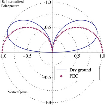
The near-field/far-field (NF/FF) transformation is a well-known technique in substitution of the direct measurement of the radiation pattern of an antenna. Many papers deal with this transformation in the case of a free-space environment [Reference Brown and Jull1, Reference Ludwig2]. On the contrary, very few results are available in the literature concerning antenna over a perfect electric conductor (PEC) [Reference Camacho-Perez and Moreno-Villalobos3] and still less over a real soil [Reference Schmidt and Eibert4]. However, the knowledge of the “in situ” radiating characteristic of an antenna is crucial. As an example, Fig. 1 shows the electric field radiation pattern of an electric vertical Hertzian dipole at 3 GHz located at the surface of a PEC compared with that obtained with the same dipole located at the surface of a real dry ground. It clearly appears, in that simple case, that the use of free-space characteristics can give rise to substantial errors in the evaluation of the “in situ” performances of an electromagnetic device using such an antenna.
Radiation pattern of a vertical Hertzian dipole placed at the surface of a PEC and at the surface of a dry ground (at 3 GHz).

This paper proposes a new NF/FF transformation able to predict the radiation pattern of an antenna placed over a real ground. It is based on the cylindrical-wave expansion of the electric field measured in the near zone and in free-space conditions. The location of the antenna over a real soil is taken into account afterwards, mathematically, by introducing a height factor as well as the reflection coefficients of the ground.
After a description of the method, first results are given considering elementary vertical and horizontal electric dipoles. The validation is performed by confrontation with the analytical formulation of the electric field radiated by a vertical or horizontal Hertzian dipole and given by Norton [Reference Norton5].
II. DESCRIPTION OF THE NF/FF TRANSFORMATION
The original method proposed in this paper derives from an NF/FF transformation based on a modal expansion of the electric field and initially expanded for a free-space configuration [Reference Brown and Jull1, Reference Ludwig2]. In the first section, we will recall the main points of development of this method and in the second section we will expose the steps of improvement allowing to set-up the antenna in a real configuration.
A) Basis: source in free-space
We start with a source in free-space and placed at the center of a cylindrical coordinate system (ρ, φ, z). We define a closed cylindrical surface S, of radius ρ 0, located in the NF zone of the source and enclosing it. Let E z(ρ 0, z) and E φ(ρ 0, z) be the components of the tangential electric field  on the surface S. We suppose that the contribution of the tangential components of the electric field on the upper and lower closing disks of the cylinder is negligible. The calculation of the spectra
 and
 of the E z(ρ 0, z) and E φ(ρ 0, z) components is appropriate to determine the electric field radiated in the far zone [Reference Brown and Jull1]. Let E θ(r, θ, φ) and E φ(r, θ, φ) be the spherical components of the FF. k z is the spectral variable associated with z and n is the angular mode of the variable φ. The cylindrical wave spectrum is defined by its transverse electric (TE) and transverse magnetic (TM) modal coefficients, respectively, a n(ρ 0, k z) and b n(ρ 0, k z). Their expressions are given as follows:
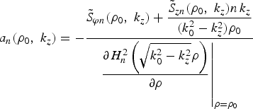
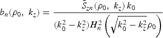
k 0 is the free-space propagation constant and H n2 is the Hankel function of second kind and of order n. By asymptotic expansion, using the saddle-point method, the components E θ(r, θ, φ) and E φ(r, θ, φ) of the FF are expressed as:


We proceed with the numerical computation of these two components by truncation of the infinite series. Indeed, the behavior of the H n2 functions with increasing values of |n| makes the high-order terms of a n(ρ 0, k z) and b n(ρ 0, k z) non-significant. The value of the rank for which the summations are stopped depends on the radius ρ 0. In a same way, as the FF zone is characterized by non-evanescent waves, the spectra of the electric field components are truncated for values of k z outside the range [−k 0, k 0].
B) Improvement: source above a real ground
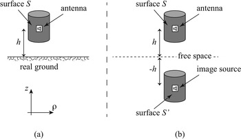
The antenna is now placed at a height h above a real plane ground of relative dielectric permittivity ɛ r and electric conductivity σ (see Fig. 2(a)).
Antenna over the ground (a) and equivalent source in free-space (b).

The application of the image principle transforms this real configuration into a pseudo free-space configuration by introducing a new source, image of the real antenna, located at a depth (−h) (see Fig. 2(b)).
We denote a n′(ρ 0, k z) and b n′(ρ 0, k z) the image modal coefficients of the tangential electric field  radiated by the image source on the surface S′ (image of the surface S). Starting with the geometric image of the real antenna, we set a property of even parity, with respect to z, on the tangential field radiated on the surface S. Hence a n′(ρ 0, k z) and b n′(ρ 0, k z) should be proportional to a n(ρ 0, −k z) and b n(ρ 0, −k z). Then, we obtain the electromagnetic image of the real antenna by weighting a n(ρ 0, −k z) and b n(ρ 0, −k z) by the spectral reflection coefficients of the ground. Finally, the coefficients a n′(ρ 0, k z), and b n′(ρ 0, k z) are related to the direct modal coefficients a n(ρ 0, k z) and b n(ρ 0, k z) of the tangential electric field
 radiated by the real antenna on the surface S by


The quantities R TE(k z) and R TM(k z) are, respectively, the spectral reflection coefficient for cylindrical TE and TM wave modes. They are functions of angular variables, θ 1 and θ 2, which represent, respectively, the incidence and refraction angles at the interface between the two half-spaces.
R TE(θ 1, θ 2) and R TM(θ 1, θ 2) are given by the following expressions:


with k z = k 0cosθ 1 and k 0sinθ 1 = k gsinθ 2.
Quantities ɛ g, μ g, and k g are, respectively, the complex dielectric permittivity, the magnetic permeability, and the complex propagation constant of the ground.
Consequently, we have to build the total cylindrical-wave spectra, in TE and TM modes, of the total tangential electric field radiated by the combination of the real antenna and its image source. For each mode, these spectra are the summation of the corresponding direct and image cylindrical-wave spectra. We denote a nT(ρ 0, k z) and b nT(ρ 0, k z) the total TE and TM modal coefficients. They are given by


The heights of the real antenna and the image source (respectively, h and −h) induce a phase-shift term  in the expression of these modal coefficients.
At the end, the method allows to deduce, by asymptotic expansion, using the saddle-point method, the FF radiating pattern of the antenna located above a real ground.
III. NUMERICAL VALIDATION
The numerical validation is realized for vertical or horizontal elementary dipoles located at a height h above two kinds of soil: sea water (ɛ r = 80 and σ = 5 S/m) and dry land (ɛ r = 15 and σ = 5 × 10⁻³ S/m). The working frequency is f = 3 GHz. We denote λ as the corresponding wavelength. The free-space NF data  are computed at ρ 0 = λ/2. The height of the cylindrical surface is fixed to 20λ.
For information, the time consumption for such a configuration (using Mathematica 8 on an iMac OS X – 2.8 GHz – Intel Core i7–16 Go RAM – 1067 MHz DDR3) is approximately 3 min and the major part concerns the computation of the spectra of the electrical field. It means that once the spectra in free space are calculated, the computation for any configuration of ground and height of antenna is quasi-instantaneous (<0.5 s).
The radiation patterns obtained with our original method are compared with those computed from the analytical formulations proposed by Norton [Reference Norton5]. These formulations allow to compute at any point above a plane ground of finite conductivity the FF radiated by a source that may be a combination of vertical and horizontal dipoles.
A) Vertical dipole
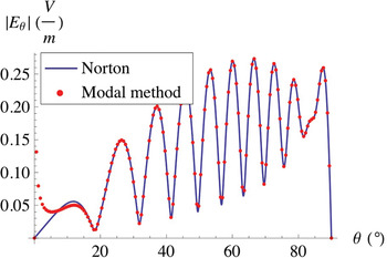
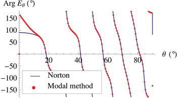
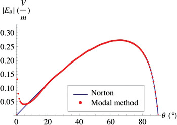
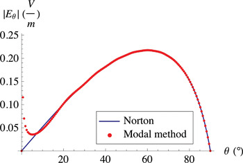
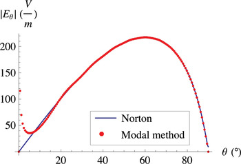
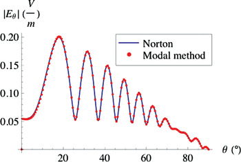
The magnitudes of the electric field radiated, at a large distance r = 10 km (105λ), by a vertical dipole located at a height h = 5λ above sea water and dry land are plotted in Figs 3 and 4, respectively. We notice, in those two cases, a good agreement between the formulation of Norton and the result of our modified modal method. Nevertheless, a slight discrepancy appears at low values of angle θ. This error issues from the truncation in height of the cylindrical surface is used to determine the NF.
Magnitude |E θ| of the electric field radiated at r = 10 km by a vertical dipole located at a height h = 5λ above sea water.

Magnitude |E θ| of the electric field radiated at r = 10 km by a vertical dipole located at a height h = 5λ above dry land.

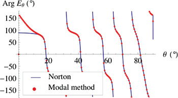
The same conclusions can be derived from Figs 5 and 6 that represent the phase of the FF in the same configurations.
Phase of the electric field E θ radiated at r = 10 km by a vertical dipole located at a height h = 5λ above sea water.

Phase of the electric field E θ radiated at r = 10 km by a vertical dipole located at a height h = 5λ above dry land.

Figs 7 and 8 concern the vertical dipole placed on sea water and on a dry land, respectively (h = 0). The prediction of the FF magnitude is always in good agreement with Norton's formula.
Magnitude |E θ| of the electric field radiated at r = 10 km by a vertical dipole placed on sea water.

Magnitude |E θ| of the electric field radiated at r = 10 km by a vertical dipole located on dry land.

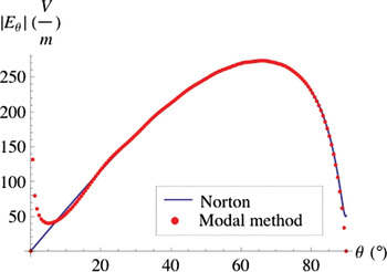
Dealing with smaller distance of observation, the magnitude of the electric field radiated at r = 10 m (100λ) by the vertical dipole placed on sea water and on dry land is plotted in Figs 9 and 10, respectively. At such a distance, Norton's formula shows a slight modification of the field grazing angle. The non-zero value at θ = 90° is due to surface wave. Our NF/FF transformation cannot predict, intrinsically, such a contribution of the total field since the NF initial data are supposed to be acquired in a free-space configuration. As shown here, this limitation has a weak effect on the values of the field obtained at higher elevation angles (θ < 90°). Moreover, when the distance of observation increases, this limitation vanishes since the surface wave becomes non-significant.
Magnitude |E θ| of the electric field radiated at r = 10 m by a vertical dipole placed on sea water.

Magnitude |E θ| of the electric field radiated at r = 10 m by a vertical dipole placed on dry land.

B) Horizontal dipole
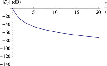
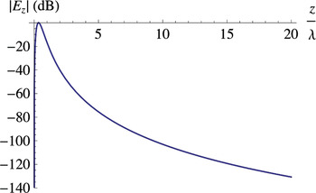
The cylindrical surface S, described in Section II.A., to sample the NF data is well suited in the case of a vertical dipole because the field is null at its zenith. On the contrary, for a horizontal dipole, the antenna radiates toward the top and the bottom of the surface S, whereas our method assumes that the field is null or negligible in these directions. To illustrate this problem, we have plotted in Figs 11 and 12, with respect to the altitude z, the magnitude of the components E φ(ρ 0, z) and E z(ρ 0, z) of the electric field radiated on the surface S by the horizontal dipole in free-space.
Magnitude |E φ| (in dB) of the electric field radiated at ρ = ρ 0 by a horizontal dipole in free-space.

Magnitude |E z| (in dB) of the electric field radiated at ρ = ρ 0 by a horizontal dipole in free-space.

It appears in Fig. 11 that a surface S with a height of few wavelengths (≅20λ) is not convenient to neglect the E φ(ρ 0, z) component at the upper edge of the sampling line. By contrast, we can see, on Fig. 12, that the E z(ρ 0, z) component is largely reduced at the top of the surface S (at z = 20λ).
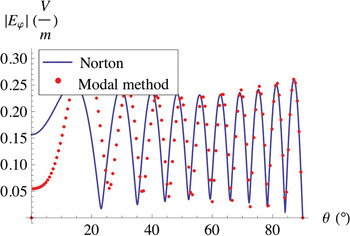
We can already deduce that a significant error will be engendered during the computation of the TE modal coefficients a n(ρ 0, k z), which are involved in the definition of the E φ(r, θ, φ) component. On the contrary, the evaluation of the TM modal coefficient b n(ρ 0, k z) is less affected and then the E θ(r, θ, φ) component too.
This behavior is illustrated in Figs 13 and 14, in which the magnitudes of the two components E φ(r, θ, φ) and E θ(r, θ, φ) of the electric FF are plotted for r = 10 km.
Magnitude |E φ| of the electric field radiated at r = 10 km by a horizontal dipole located at height h = 5λ above dry land.

Magnitude |E θ| of the electric field radiated at r = 10 km by a horizontal dipole located at height h = 5λ above dry land.

IV. CONCLUSION
The NF/FF transformation presented in this paper allows, starting with the measurement of the NF in free-space configuration (in an anechoïc chamber, e.g.), to compute the FF radiated by an antenna above a real ground. In the spectral domain, the image principle is applied for TM and TE polarizations. Then, the FF is retrieved using full spectrum (direct and image). The results obtained with this new NF/FF transformation are often close to the theoretical ones. Two limitations have been pointed out: the noticeable presence of surface wave and the significant radiation toward the zenith. Nevertheless, surface waves could be neglected at large distances or when the antenna is raised over the ground. If the antenna radiates toward the zenith, it should be more appropriate to define a spherical surface in the near zone and to apply a spherical expansion of the electric field spectra. Finally, the NF/FF transformation presented in this paper is an efficient way to predict the radiating characteristic of an antenna in its operational context using measurements performed in controlled environment.
 Nicolas Payet received his Master degree in electrical engineering from Pierre and Marie Curie University (UPMC), Paris, France, in 2009. He is currently working toward the Ph.D. degree in UPMC. His researches are focused on the characterization of HF antenna from near-field measurement.
 Muriel Darces was born in 1971 in Paris, France. She received the Ph.D. degree from the Pierre and Marie Curie University (UPMC) of Paris, France, in 1997. Her present status is an assistant professor in Electronic and Electromagnetism at the Pierre and Marie Curie University. Her research interests are currently focused on the characterization of HF antenna from near-field measurement and the study of the specific propagation mode by surface wave in HF applications.
 Marc Hélier was born in Paris, France, in June 1958. He received the Diplôme d'Ingénieur from the École Supérieure d'Électricité (Supélec), Gif-sur-Yvette, France, in 1981, and the Diplôme de Docteur-Ingénieur from the University of Paris-Sud, Orsay, France, in 1983. From 1985 to 2001, he was an Assistant Professor at Supélec, Gif-sur-Yvette, France, at the Laboratoire des Signaux et Systèmes, CNRS-Supélec, where he was involved in studies on theoretical and practical aspects of wire and printed antennas, RCS calculation and measurement, and application of probability and statistics to electromagnetic compatibility. From 2001 to now, he is a full-time Professor at the Pierre and Marie Curie University-Paris 6, in Paris, France. His current research interests include electromagnetic compatibility for automotive and defense applications, array antennas, design of HF antennas, and mitigation of sea and ionospheric clutter in High Frequency Surface Wave Radar applications.
 Jean-Louis Montmagnon received his Ph.D. in 1981 from the Physics department of Université Pierre et Marie Curie- Paris-France (UPMC). He is working at the UPMC since 1974. He is the author of articles on atomic physics and, since 2004, his current researches include microwave circuits and determination of far-field antenna patterns from near-field measurements. He is also interested in HF antennas that can radiate a surface wave.
 Florent Jangal received his Ph.D. in 2007 and joined the Onera's Low Frequency Radar unit the same year. He is involved in several projects dealing with defense and security application of High Frequency Surface Wave Radars. He is currently working on improvement of surface wave excitation and evaluation of MIMO concept for High Frequency Surface Wave Radar.