Introduction
Millimeter wave (mm-wave) technologies are among the most promising technologies for wireless systems beyond 5G and 6G thanks to their ability to take advantage of abundant unused spectrum resources [Reference Roberts, Zhang, Osman and Alkhateeb1, Reference Ahmad, Mahmood and Alsawaf2]. Millimeter waves have the advantage of high bandwidth but suffer from poor propagation in real environments due to large signal loss and easy blockage [Reference Abed and Ayoob3–Reference Qeryaqos and Ayoob5]. Compared to frequencies below 6 GHz, mm wave frequencies are easier to block through higher Directivity. IRSs (Intelligent Reflecting Surfaces) have been an inexpensive and cost-effective solution to this problem. IRS stands for a smart surface that is capable of intelligently reflecting radio waves through phase control of waves while interacting with its surface [Reference Wu and Zhang6]. Because IRS is used in mm-wave communications, it is a perfect technology for networks that will be 5G and beyond [Reference Li, Guo, Tao, Liu and Yu7]. The RIS (Reconfigurable Intelligent Surface) technology has attracted lots of attention of late, and the current paper was focused on areas such as precoding design [Reference Zhang and Dai8, Reference Wang, Fang, Yuan, Chen and Li9], channel estimation [Reference Ma, Shen, An and Hanzo10, Reference Hu, Dai, Han and Wang11], and architectural design [Reference Liu, Zhang, Dai, Xu and Yang12], with major interest being in narrowband applications. Consider RIS technique has already been employed with excellent success to various communications systems for improving the user’s reception quality of the received signal [Reference Wang, Fang, Yuan, Chen and Li9]. A greater weighted sum rate was achieved with a block coordinate descent algorithm to optimize the parameters of base stations and RIS separately and thus enhance system performance [Reference Pan, Ren, Wang, Xu, Elkashlan, Nallanathan and Hanzo13]. Substantial research has been conducted to examine the prospective uses of RIS technology in broadband communication systems, particularly in mm-wave frequency bands [Reference He, Xu, Shen, Xie, Zhao and Di Renzo14–Reference Wang, Yang, Makki and Shamim18]. The authors demonstrated the effectiveness of using RIS-aided hybrid relay networks in mm-wave communication systems, particularly when combined with advanced machine learning techniques [Reference Zhao, Liu, Liu, Wang and Huang19]. The use of conventional beamforming methods in large IRS mm-wave deployments results in undesirable scattering of beams across a variety of frequency and angular spaces. This phenomenon is known as beam splitting, and it represents a greater challenge in mm-wave communications than beam squint [Reference Chen, Chen and Jiang16, Reference Dai, Tan, Chen and Poor20–Reference Park, Kim, Kim, Dai, Wong and Chae23]. In the study by Chen et al. [Reference Chen, Chen and Jiang16], the authors used channel covariance matrix and long-range angle information to develop a technique aimed at improving data transmission rate in environments affected by beam splitting. Although deployment of distributed IRSs will reduce the problem of beam splitting to a large extent, it renders a high loss in received signal strength since elements constituting the surface are quite small. In addition, all the methods proposed in study by Chen et al. [Reference Chen, Chen and Jiang16] rely on precoding techniques that are invariant across frequencies. In paper by Li et al. [Reference Li, Shao, Sun, Tao and Zhang24], the authors presented scientific inputs to the immense potential of remote sensing systems in enhancing mm-wave communication and sensing systems by optimizing the key parameters such as beam scanning, beam splitting, and performance evaluation techniques accurately. The study [Reference Yan, Hao, Sun, Huang and Wu25] presented two new designs of a simultaneous transmit and receive RIS (STAR-RIS) for applicationin terahertz (THz) communication systems. These two designs have been suggestedto mitigate the beam splitting effects, which is a major challenge in high-frequency communication systems.
The proposed approach addresses the beam-split effect and ensures beam alignment across all frequencies, focusing on a wideband-specific design that considers frequency dispersion in mm-wave channels. Unlike previous studies that treat IRS and precoding separately, leading to suboptimal performance, this approach jointly designs IRS and precoding for improved performance. The system optimizes signal routing using IRS to mitigate path loss effectively. Moreover, it focuses on computational efficiency for large systems with a high number of IRS elements and sub-frequencies, which has not been satisfactorily addressed before.
The proposed solution addresses this problem through low-complexity algorithms that work efficiently with large-scale systems.
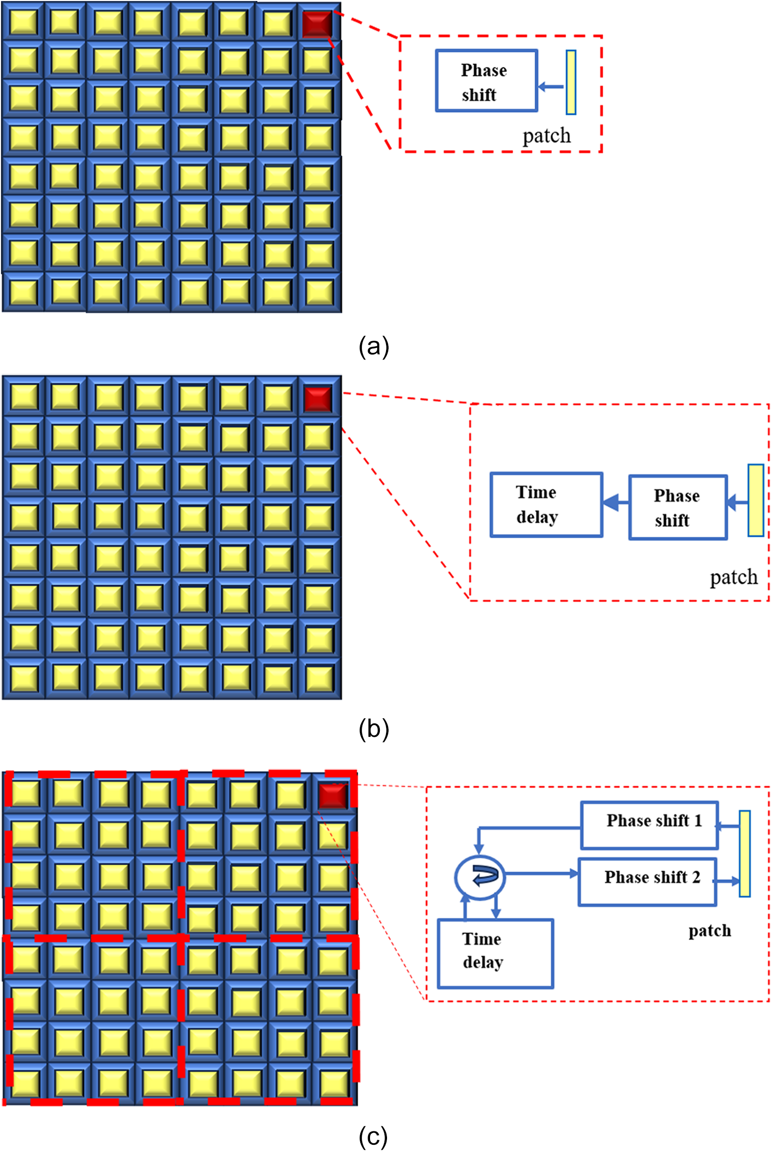
This paper contributes to mitigating the effect of beam split in IRS. A sublayered IRS architecture with fewer time delay (TD) units is proposed. The subarray element is composed of a cascaded connection of two-phase shifters and a shared time delay module. The elements receive and process the signal sequentially, with the signal passing through first phase shifter, the TD unit, and then the second phase shifter. This setup permits a transition from traditional narrowband precoding, which relies solely on phase, to wideband precoding based on a combination of TD and phase shift, leading to an enhanced tradeoff between data rate, device cost, and power dissipation.
A wideband frequency-dependent precoder design is presented based on the sub-connected architecture. This design aims to constructively generate overlapping signals to be assembled into different receiving elements by controlling the phases of the first layer of the subarray. The beam must be directed towards the carrier frequency to the receiving end by the second layer. For each sub-carrier, the common time delay unit aligns it so that the produced beams precisely match the desired physical direction.
The remainder of this paper is structured as: Section 2 introduces a comprehensive model of the system and signal. Section 3 discusses the effect of beam splitting on the IRS, while Section 4 presents the proposed IRS architecture along with its design analysis. The outcome and simulation will be explained in Section 5, and Section 6 summarizes the paper.
Notations: Bold letters represent mathematical quantities, where uppercase letters indicate matrices and lowercase letters indicate vectors.
 ${A^T}$: The matrix is created by interchanging the rows and columns of matrix
 $A$.
 ${A^H}$: The matrix is created by applying the conjugate operation to the elements in the matrix
 ${A^T}$.
 $\left| a \right|$: The vector length
 $a$.
 $\mathbb{E}\left[ Z \right]$: The average expected value of the random variable Z.
 $U\left( {a,b} \right)$: Probability Distribution in which each value between b and a has equal likelihood.
 $ \otimes $: Kronecker multiplication is a special multiplication of two matrices.
 $\odot$: Hadamard multiplication, Another unique matrix multiplication operation between two matrices,
diag( $a$): a diagonal matrix with the vector elements on the main diagonal
System and signal model
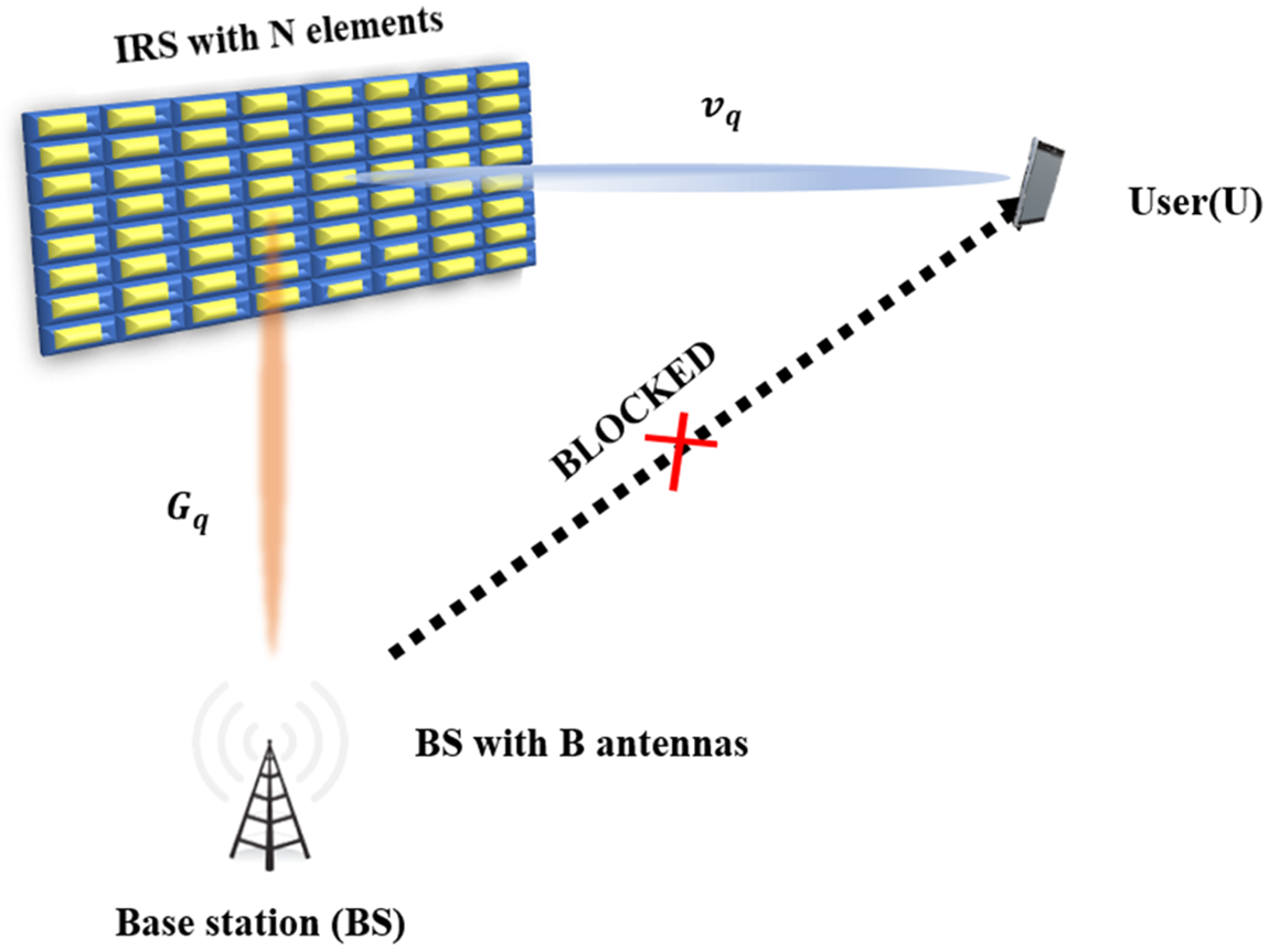
This paper investigates mm-wave communication with an IRS, as indicated in Fig. 1. Specifically, it examines a system in which a BS equipped with a uniform linear array (ULA) of antennas ( $B$) employs an IRS to transmit signals to a single user. While the model can be generalized to the multi-user scenario, a single-user model is adopted for simplicity. The IRS is a uniform planar array (UPA) and consists of N IRS elements which are equal to
 ${N_1}{N_2}$ where
 ${N_1}$and
 ${N_1}$ represent the IRS elements in the horizontal and vertical direction, respectively. The sub-carriers (Q) in orthogonal frequency division multiplexing (OFDM) technology are utilized to modulate the user signals and mitigate wideband channel dispersion. The IRS is positioned in the x–y plane, with the BS at (0,0), the IRS at (0, 25 m), and the user at (25 m, 25 m).
The IRS-assisted mm-wave technique.

The received signal at qth subcarrier is given [Reference Chen, Chen and Jiang16]:
 \begin{align}
{y_q} &= (v_q^T{{\Theta }}{G_q} + {h_q}){x_q} + {n_q} \nonumber\\
{y_q} &= v_q^T\Theta {G_q}{x_q} + {n_q}\end{align}
 ${h_q}:{\text{ }}$the direct channel from BS to user,which is blocked,
 ${v_q}$: the channel from IRS to user,
 $v_q^T = \left[ {{v_{q,1}},} \right]$
 \begin{equation}{{\Theta }} = diag\left( \theta \right) = diag\left( {{e^{j{\theta _1}}},{e^{j{\theta _2}}},{\text{ }} \ldots \ldots .,{e^{j{\theta _N}}}} \right)\end{equation}
The IRS phase shift matrix ( ${{\Theta }}$) is diagonal,which each diagonal entry
 ${e^{j{\theta _N}}}$ corresponds to a phase shift introduced by the
 $n$th IRS element [Reference Alsawaf and Ayoob26]. Each element in IRS adjusts the phase of the incoming signal to maximize the constructive alignment of signals at the user. This is key for beamforming or mitigating beam-split effects.
 ${{\Theta }}$: The IRS reflection coefficient, it was considered that the reflection amplitude at the IRS is constant [Reference Li, Guo, Tao, Liu and Yu7, Reference Torcolacci, Guerra, Zhang, Guidi, Yang, Eldar and Dardari27],
 ${G_q}$
 $ \in {\text{ }}{\mathbb{C}^{N \times B}}$: the channel from BS to IRS,
 ${x_q} = w{r_q} \in {\text{ }}{\mathbb{C}^{B \times 1}}$ is the transmitted signal at the BS,
 $w \in {\mathbb{C}^{B \times 1}}$ is the precoding vector, at the q th subcarrier,
 ${r_q}$
 $ \in {\text{ }}\mathbb{C}$ denoted the information of transmitting, which fulfilled
 $\mathbb{E}\left[ {{{\left| r \right|}^2}} \right] = 1$,
 ${n_q}$: presents the Additive White Gaussian Noise (AWGN) with mean = 0,and variance
 ${\sigma ^2}{\text{ }}$ [Reference Xiu, Zhao, Sun, Renzo, Gui, Zhang and Wei28, Reference Qeryaqos and Ayoob29].
The IRS has a line of sight directly . Thus, the channel of BS-IRS is expressed as [Reference Ning, Chen, Chen, Du and Fang30–Reference Mei and Zhang32]:
 \begin{equation}{G_q}{ = _1}{e^{ - j2\pi {f_q}{t_1}}}k{\text{ }}{b^H}\end{equation}
 ${G_q}$ discribed how the signal propagates from the BS to the IRS, accounting for path loss
 ${t_1}{\text{ }} \in {\mathbb{R}^ + }$, phase delays
 ${e^{ - j2\pi {f_q}{t_1}}}$, and array response vectors at both ends,
 ${g_1} \in \mathbb{C}$ represented the BS-IRS path gain. The frequency of subcarrier
 ${q^{th}}$ is determined according to the following equation [16, Reference Li, Sun and Tao33]:
 \begin{equation}{f_q} = {f_c} + \frac{{{f_s}}}{Q}\left( {q - 1 - \frac{{Q - 1}}{2}} \right)\end{equation}
 ${f_c}$: the carrier frequency,
 ${\text{ }}{f_s}$: the bandwidth,
 $d = \frac{\lambda }{2} = \frac{c}{{2{f_c}{\text{ }}}}$ denoted to the distance between the base station antennas; it also represents the distance between the IRS elements, c denoted speed of light and
 $q = 1,2, \ldots ,Q.$
 $\emptyset $: Symbolized the transmission angle of the BS.
 ${\alpha _1}$ and
 ${\beta _1}$ represented the elevation and azimuth angles of the direction from which the signal arrives at the IRS. These angles are constrained by the following conditions:
 $\beta \in U\left( { - \pi ,\pi } \right)$,
 $\alpha \in U\left( {0,\frac{\pi }{2}} \right)$ and
 $\emptyset \in \left( { - \frac{\pi }{2},\frac{\pi }{2}} \right)$. The BS-IRS path gain is expressed [Reference Ning, Chen, Chen, Du and Fang30]:
 \begin{equation}{g_1} = \frac{c}{{4\pi {f_q}{d_1}}}{e^{\frac{{ - \tau {d_1}}}{2}}} \approx \frac{c}{{4\pi {f_q}{d_1}}}\end{equation}
The term  ${e^{\frac{{ - \tau {d_1}}}{2}}}$ can often be neglected at mm-wave since molecular absorption is minimal in this frequency range.
 ${\text{ }}{d_1}$ represents the distance between the IRS and the Base Station (BS), while
 ${\text{ }}\tau $ representing the effect of the molecular absorption.
k is the IRS steering vector with UPA that is defined as [Reference Ling, Han, Jin and Matthaiou34, Reference Pei, Yin, Tan, Cao, Li, Wang, Zhang and Björnson35]:
 \begin{align}k &= \frac{1}{{\sqrt {{N_1}{N_2}} }}{\left[ {1, \ldots .,{e^{\frac{{j2\pi {f_q}}}{c}\left( {{N_1} - 1} \right)dsin{\alpha _1}cos{\beta _1}}}} \right]^T} \nonumber\\
&\quad \otimes {\left[ {1, \ldots .,{e^{\frac{{j2\pi {f_q}}}{c}\left( {{N_2} - 1} \right)dsin{\alpha _1}sin{\beta _1}}}} \right]^T}\end{align}
The steering vector ( $k$) describes the phase shifts applied to each IRS element in order to steer the beam in specific spatial directions (
 $\alpha ,\beta $). The terms
 ${e^{\frac{{j2\pi {f_q}}}{c}\left( {{N_1} - 1} \right)dsin{\alpha _1}cos{\beta _1}}}$ and
 ${e^{\frac{{j2\pi {f_q}}}{c}\left( {{N_2} - 1} \right)dsin{\alpha _1}sin{\beta _1}}}$ represented the difference across elements,determined by the spatial direction (
 $\alpha ,\beta $),
 ${f_q}$ and number of elements (
 ${N_1},{N_2}$) and spacing (
 $d$).
 $b$ is The base station steering vector with ULA, which is defined as [Reference Tan and Dai36]:
 \begin{equation}b = \frac{1}{{\sqrt B }}{\left[ {1, \ldots .,{e^{\frac{{j2\pi {f_q}}}{c}\left( {B - 1} \right)dsin\emptyset }}} \right]^T}\end{equation}
 $B$: Number of transmit antenna at the BS,
 $\emptyset$: Azimuth angle . The steering (
 $b$) vector models the phases of signals across the transmit antennas at the BS, which are aligned to focus energy in the desired transmission direction
 $\emptyset $. It accounts for the spatial direction and frequency, making beamforming possible.
Similarity, the IRS-to-user channel is also specified [Reference Wei, Zhao, Zhao and Cai37]:
 \begin{equation}{v_q} = {g_2}{\text{ }}{e^{ - j2\pi {f_q}{t_2}}}k\end{equation}
The equation (8) models the IRS-U channel by considering path loss  ${g_2}$, phase delays, and the steering vector of IRS. It ensures that IRS aligns the signals reflected to the user (U) .
Where,  ${g_2} \in {\text{ }}\mathbb{C}$: the path gain channel (IRS-U),
 ${\beta _2}$ and
 ${\alpha _2}$ are the elevation and azimuth angles of the Angle of Depature (AoD),
 ${t_2} \in {\mathbb{R}^ + }$represented the path delay,
 ${g_2}$ is given by [Reference Li, Shao, Sun, Tao and Zhang24]:
 \begin{equation}{g_2} = \frac{c}{{4\pi {f_q}{d_2}}}{e^{\frac{{ - \tau {\text{ }}{d_2}}}{2}}} \approx \frac{c}{{4\pi {f_q}{d_2}}}\end{equation}
 ${d_2}$: The distance from IRS to user (U).
At the  ${q^{th}}$ subcarrier,the gain of array is described using the system model, according to Yan et al. [Reference Yan, Hao, Sun, Huang and Wu25]:
 \begin{equation}A = {\text{ }}\left| {v_q^T{{\Theta }}{G_q}w} \right| = \left| {{g_1}{g_2}{e^{ - j2\pi \left( {{t_1} + {t_2}} \right){f_q}}}} \right|.\left| {{k^T}{{\Theta }}k{b^H}w{\text{ }}} \right|\end{equation}
Equation (10) combined all the components – BS, RIS, and UE – to express the total array gain, describing the impact of beamforming and IRS optimization.
Beam split analysis
The impact of beam split and its resulting gain of array and loss analysis were performed on an IRS surface. From equation (10), at  ${q^{th}}$ subcarrier, the normalized gain of array of the IRS was given by:
 \begin{align}
{A_{IRS}} &= \left| {{k^T}{{\Theta }}k{b^H}{\text{ }}} \right|\nonumber\\
{A_{IRS}} &= \frac{1}{{{N_1}{N_2}}}\left| {\sum\nolimits_{{n_1} = 0}^{{N_1} - 1} \sum\nolimits_{{n_2} = 0}^{{N_2} - 1} {e^{j\pi m\left[ {{n_1}\left( {{a_1} + {a_2}} \right) + {n_2}\left( {{\vartheta _1} + {\vartheta _2}} \right)} \right]}}{\text{ }}} \right|.{e^{j{\theta _\ell }}}\end{align}
Where,  $\ell = {N_2}{n_1} + {n_2} + 1$,
 ${a_1} = sin{\alpha _1}cos{\beta _1}$,
 $\vartheta_1=\sin \alpha_1 \sin \beta_1$,
 ${a_2} = sin{\alpha _2}cos{\beta _2}$,
 $\vartheta_2=\sin \alpha_2 \sin \beta_2$,
 $m = \frac{{{f_q}}}{{{f_c}}}$ the relative frequency . The IRS beamforming vector was calculated using the transmitted signal’s carrier frequency as follow:
 \begin{equation}{\theta _\ell } = - \pi \left[ {{n_1}.\left( {{a_1} + {a_2}} \right) + {n_2}.\left( {{\vartheta _1} + {\vartheta _2}} \right)} \right]\end{equation}
Let  ${g_1}$ and
 ${g_2}$ remains constant, the normalized array gain
 $\left( {{A_{IRS}}} \right)$ in equation (11) is written more succinctly as:
 \begin{equation}{A_{IRS}} = \frac{1}{{{N_1}{N_2}}}\left| {\sum \nolimits_{{n_1} = 0}^{{N_1} - 1} \sum \nolimits_{{n_2} = 0}^{{N_2} - 1} {e^{j\pi \left( {m - 1} \right)\left[ {{n_1}\left( {{a_1} + {a_2}} \right) + {n_2}\left( {{\vartheta _1} + {\vartheta _2}} \right)} \right]}}{\text{ }}} \right|\end{equation}
 \begin{equation}{\text{ }}{A_{IRS}}\mathop = \limits^{\left( i \right)} {\mathbb{A}_{{N_1}}}\left( {\left( {m - 1} \right)\left( {{a_1} + {a_2}} \right)} \right){\mathbb{A}_{{N_2}}}\left( {\left( {m - 1} \right)\left( {{\vartheta _1} + {\vartheta _2}} \right)} \right)\end{equation}
Where (i) comes from  $\sum^{N-1}_{n=0}e^{jn\pi x} = \frac{\sin\frac{N\in x}{2}}{\sin \frac{N\pi}{2}}e^{\frac{-j\pi(N-1)x}{2}}$ and
 ${\mathbb{A}_N} = \frac{{sin\frac{{N\pi x}}{2}}}{{Nsin\frac{{\pi x}}{2}}}$ is the Dirichlet Sinc Function [Reference Tan and Dai36].
Although the beam-splitting effect, caused by the intersection of a high number of IRS elements and broad bandwidth in mm-wave communications, is a significant problem resulting in a decrease in array gain, it is a challenge that spoils the potential advantage of IRS technology. To counter this issue, a wideband precoding method which modifies phase and delay simultaneously is introduced.
Design of irs structure
In this paper, a sub-connected PTDP architecture for IRS was proposed, replacing the conventional architecture depicted in Fig. 2a, for device cost saving. Frequency-selective precoding supported by the use of time delay units for every element in the IRS architecture in Fig. 2(b) [Reference Liu, Zhang, Dai, Xu and Yang12, Reference Tan and Dai36] effectively solves the beam splitting problem.Time delay units are power consuming and costly to accomplish compared to phase shifing. The sub-connected delay-phase architecture used in the Ref [Reference Tan and Dai36]. for BSs can’t be extended directly to IRS, as destructive interference would occur due to the common TD unit. The considered structure, Fig. 2c utilizes two phase shifters per sub-array element that are linked by a shared TD unit via a circulator. A significant superposition of the signals is achieved by the main phase shifter layer of the subarray. Then, the time delay model shifts the signals timing, and the second phase shifter layer directs the resultant beam towards the required direction. The of proposed IRS structure is constructed with the help of two small antenna patches, each consisting of two layers of phase shifting. Compared to conventional time delay modules, the application of low-resolution phase shifters allows for significant power saving and hardware cost reduction. Furthermore, low-resolution components can be used by the integrated phase shifters to save power and reduce costs [Reference Huang, Alexandropoulos, Zappone, Debbah and Yuen38].
IRS architecture: (a) traditional IRS (B) IRS with TD and phase shift (c) proposed PTDP.

For the IRS-assisted mm-wave technology, it was assumed that the IRS is divided into  $S = {S_1}{S_2}$ sub-arrays, where every sub-array is linked to a TD unit. Each sub-array include
 ${\text{ }}P = {P_1}{P_2}$ elements, where P1 = N1/S1 and P2 = N2/S2. P1 and P2 values were converted into integers. Subarray parameters are set as
 ${\text{ }}{s_1} = {\text{ }}1,2,{\text{ }}\ldots,{\text{ }}{S_1}$, and
 ${s_2} = 1,{\text{ }}\ldots,{\text{ }}{S_2}$. The parameters of the elements in the individual subarray are taken as follows:
 ${\text{ }}{p_1} = 1,{\text{ }}\ldots,{\text{ }}{P_1}$, and
 ${p_2} = 1,{\text{ }}\ldots,{\text{ }}{P_2}$.
Following structural modifications and subarray division, channel equations (3) and (8) are rewritten as the BS-IRS channel model introduced by the following equation:
 \begin{equation}{G_q} = \frac{{{g_1}}}{{\sqrt {{N_1}{N_2}} }}{e^{ - j2\pi {f_q}{t_1}}}\underbrace {{e^{j\pi m({n_1}a + {n_2}\vartheta }}}_{steering\;matrix}\end{equation}
The channel of IRS-U is:
 \begin{equation}{v_q} = \frac{{{g_2}}}{{\sqrt {{N_1}{N_2}} }}{\text{ }}{e^{ - j2\pi {f_q}{t_2}}}{e^{j\pi m\left( {{n_1}a + {n_2}\vartheta } \right)}}{\text{ }}\end{equation}
Where  $a = sin\alpha cos\beta $,
 $\vartheta = sin\alpha sin\beta ,$
 ${n_1} = {s_1}{P_1} + {p_1}$,
 ${n_2} = {s_2}{P_2} + {p_2}$
As seen in the equations (15) and (16), the channels  ${G_q}$ and
 ${v_q}$ are divided into subarrays.
 $G_q^s$ denoted the channel of the IRS subarray. The TD is
 ${t_s}{\text{ }} \in {\mathbb{R}^ + }$,
 ${{\Theta }}_1^s$ the first layer phase shift,
 ${{\Theta }}_2^s$ the second layer phase shift associated with sth subarray, and
 $s = {s_2}{S_1} + {s_1} + 1$. The vector of TD
 $\left( {{{\textrm T}_q}} \right)$ of the elemnts of IRS is given by Dal et al. [Reference Dai, Tan, Chen and Poor20]:
 \begin{equation}{{\textrm T}_q} = {e^{ - j2\pi {f_q}t}},{\text{ }}t = \left[ {{t_1},{t_2}, \ldots .,{t_s},{t_S}} \right]\end{equation}
Hence, the signal through the first phase-shifting layer of the sth IRS subarray is written as
 \begin{equation}\mathcal{Y}_{1,q}^s = \sum \nolimits_{q = 1}^Q \Theta _1^s \odot G_q^s\end{equation}
After going through the second phase-shifting layer, the user receives the signal:
 \begin{equation}\mathcal{Y}_{2,q}^s = \sum \nolimits_{q = 1}^Q \left( {v_q^s \odot \Theta _2^s{\textrm T}_q^s\mathcal{Y}_{1,q}^s} \right)\end{equation}
Introducing phase shifts at two different stages allows for better control of the direction and timing of the reflected signals. A TD vector ( ${\textrm T}_q^s$) is applied to ensure that across the subcarriers, alignment in the time domain improves to mitigate the beam split effects. Equations (18) and (19) are applied to obtain the gain of the
 ${q^{th}}$ subarray of the IRS at the qth subcarrier:
 \begin{equation}{A_s} = \left| {\sum \nolimits_{q = 1}^Q \left( {v_q^s \odot \left[ {\Theta _2^s{\textrm T}_q^s.\sum \nolimits_{q = 1}^Q \left( {\Theta _1^s \odot G_q^s} \right)} \right]} \right){\text{ }}} \right|\end{equation}
Equation (20) shows that if time delays and phase shifts are added as proposed design parameters, it leads to achieving high array gains across different subcarriers of the proposed PTDP design, which in turn leads to mitigating the beam splitting effect.
PTDP-based IRS performance was quantified in terms of observing array gain. For solving beam splitting, a wideband precoding scheme was designed. The array gain for the  ${q^{th}}$ subcarrier was determined via equation (20):
 \begin{align}
& A = \bigg| \sum \nolimits_{{s_1} = 1}^{{S_1}} \sum \nolimits_{{s_2} = 1}^{{S_2}} \bigg\{ \sum \nolimits_{q = 1}^Q \bigg( v_q^s \odot \bigg[ \Theta _2^s{\textrm T}_q^s. \sum \nolimits_{q = 1}^Q \\ \nonumber
&\qquad \qquad \qquad \qquad \qquad \qquad \qquad\left( {\Theta _1^s \odot G_q^s} \right) \bigg] \bigg) \bigg\}{\text{ }} \bigg|\end{align}
The optimization problem for maximizing the array gain over all subcarriers is:
 \begin{equation}\frac{{\max }}{{{\Theta _1},{\Theta _2},\,t}}\frac{1}{Q}\sum\nolimits_{q = 1}^Q A \end{equation}
Wideband precoding performance gains at the qth subcarrier for PTDP-based are conditioned on (23) to (25).
 \begin{align}{t_s} &= \frac{1}{{2{f_c}}}\left[ \left( {\left( {{s_1} - 1} \right){P_1} - \frac{{\left( {{P_1} - 1} \right)}}{2}} \right)\left( {{a_1} + {a_2}} \right)\right. \nonumber\\
&\quad \left.+ \left( {\left( {{s_2} - 1} \right){P_2} - \frac{{\left( {{P_2} - 1} \right)}}{2}} \right)\left( {{\vartheta _1} + {\vartheta _2}} \right) \right]\end{align}
 \begin{equation}\Theta _1^s = {e^{ - j\pi \left( {{p_1}{a_1} + {p_2}{\vartheta _1}} \right)}}\end{equation}
 \begin{equation}\Theta _2^s = {e^{ - j\pi \left( {{p_1}{a_2} + {p_2}{\vartheta _2}} \right)}}\end{equation}
The equation (23) shows that the optimal time delay depends on the size of the sub-array (parameters  ${P_1}$and
 ${P_2}$) and the angular parameters
 $a$ and
 $\vartheta $ related to the signal direction. Properly introducing time delays compensates for frequency-dependent beam misalignment. As equation (18) is a scalar value, the maximization of equation (22) is equivalent to the maximization of equations (18) and (19) individually.
The array gain of the proposed PTDP was subsequently defined, having been determined through the resolution of the equation (21) [Reference Dai, Tan, Chen and Poor20]:
 \begin{align}A &= \frac{{{S_1}{S_2}{P_1}{P_2}}}{{{N_1}{N_2}}}|{\text{ }}{\mathbb{A}_{{P_1}}}\left( {\left( {m - 1} \right){a_1}} \right){\mathbb{A}_{{P_1}}}\left( {\left( {m - 1} \right){a_2}} \right) \nonumber\\
&\quad .{\mathbb{A}_{{P_1}}}\left( {\left( {m - 1} \right){\vartheta _1}} \right){\mathbb{A}_{{P_1}}}\left( {\left( {m - 1} \right){\vartheta _2}} \right)\end{align}
The stages involved in PTDP beamforming are illustrated in Algorithm 1. Ideal Phase Shift differs from PTDP Phase Shift in that the ideal was calculated directly from the IRS element’s frequency and index. The second one, contains a delay component adjusted in order to offset sub-arrays and sub-array layers’ phase shifts. According to equation (12), the IRS’s optimal beamforming vector ought to be frequency-dependent [Reference Chen, Chen and Jiang16]:
 \begin{equation}{\theta _{opt,\ell }} = - \pi m\left[ {{n_1}.\left( {{a_1} + {a_2}} \right) + {n_2}.\left( {{\vartheta _1} + {\vartheta _2}} \right)} \right]\end{equation}
The proposed PTDP architecture for IRS has transformative practical implications in several scenarios, including:

1. High-Speed Wireless Networks: Beamforming and signal alignment can be improved for 5G/6G mm-wave communication to increase reliability and throughput.
2. Dense Urban Areas: Path loss and interference are minimized in dense areas, providing stable IRS assisted connections.
3. Autonomous Systems: Provides precise beam steering for real-time data transfer in autonomous vehicles and drones, providing low latency in communication.
4. Industrial IoT and Smart Manufacturing: It improves communication within IoT networks by enhancing the quality of the signal to facilitate automation in industries effectively.
There are essential differences between the proposed PTDP and Ref. [Reference Yan, Hao, Sun, Huang and Wu25]:
Difference in operating mode and functionality: In [Reference Yan, Hao, Sun, Huang and Wu25], the STAR-RIS system is used for joint reflection and transmission control, introducing additional challenges in the wideband beamforming design from the aspect of managing three-sided beam splitting. Our contribution is devoted to the conventional reflection-only IRS scenario in order to empower sophisticated precoding schemes for the mm-wave scenario.
Impact of side structure on system performance: As mentioned by the reviewer, our paper’s RIS structure is a special case of STAR-RIS in [Reference Yan, Hao, Sun, Huang and Wu25], but it ignores the geometrical and radiation implications of having two separate surfaces in STAR-RIS versus one surface in conventional RIS. This difference leads to varying mathematical formulations and optimization methods, and thus the two approaches are not equivalent in performance and computational complexity.
Research focus and explicit applications: The present research attempts to provide customized solutions for conventional IRS configurations in mm-wave communication systems with proficiency in Wideband Precoding techniques, whose mathematical formulations and analyses differ from what is used in STAR-RIS.
Therefore, structural similarity is not equal to similar modeling, analysis, and applications because the diversity of the research goals and theory makes up the different approach that suits a different set of real-world situations.
Simulation results
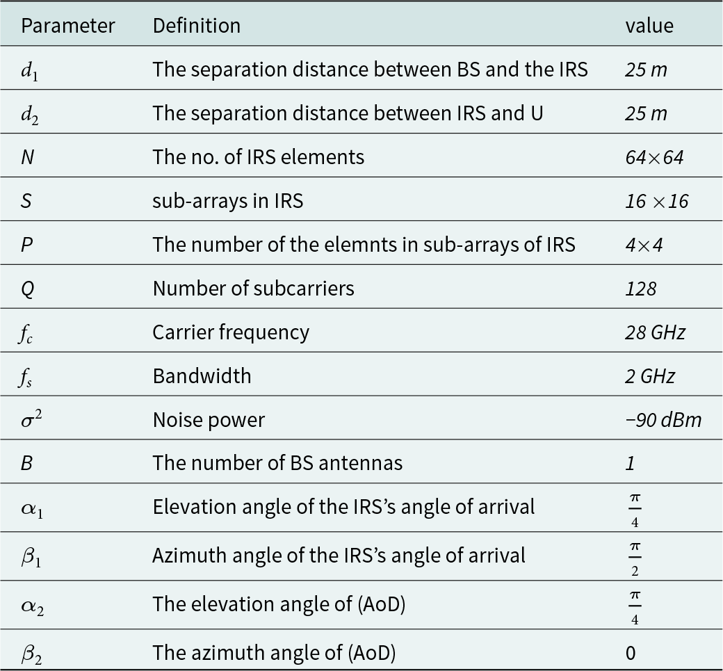
The simulation of an IRS-aided mm-wave communication system, presented in Sections 3 and 4 and illustrated graphically in Fig. 1, was conducted with the parameters listed in Table 1. It is assumed that the channel state information CSI is perfectly available [Reference Wang, Fang, Yuan, Chen and Li9], obtained using the techniques in [Reference Ma, Shen, An and Hanzo10, Reference Hu, Dai, Han and Wang11].
Applied parameters in the simulation

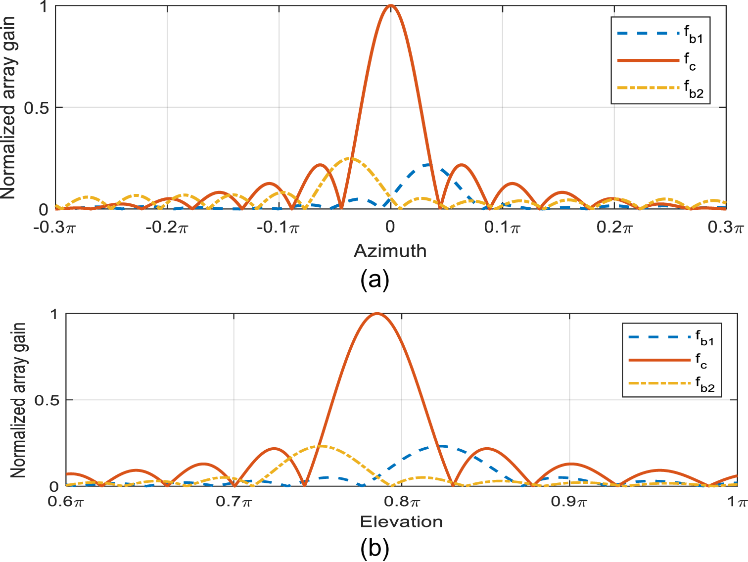
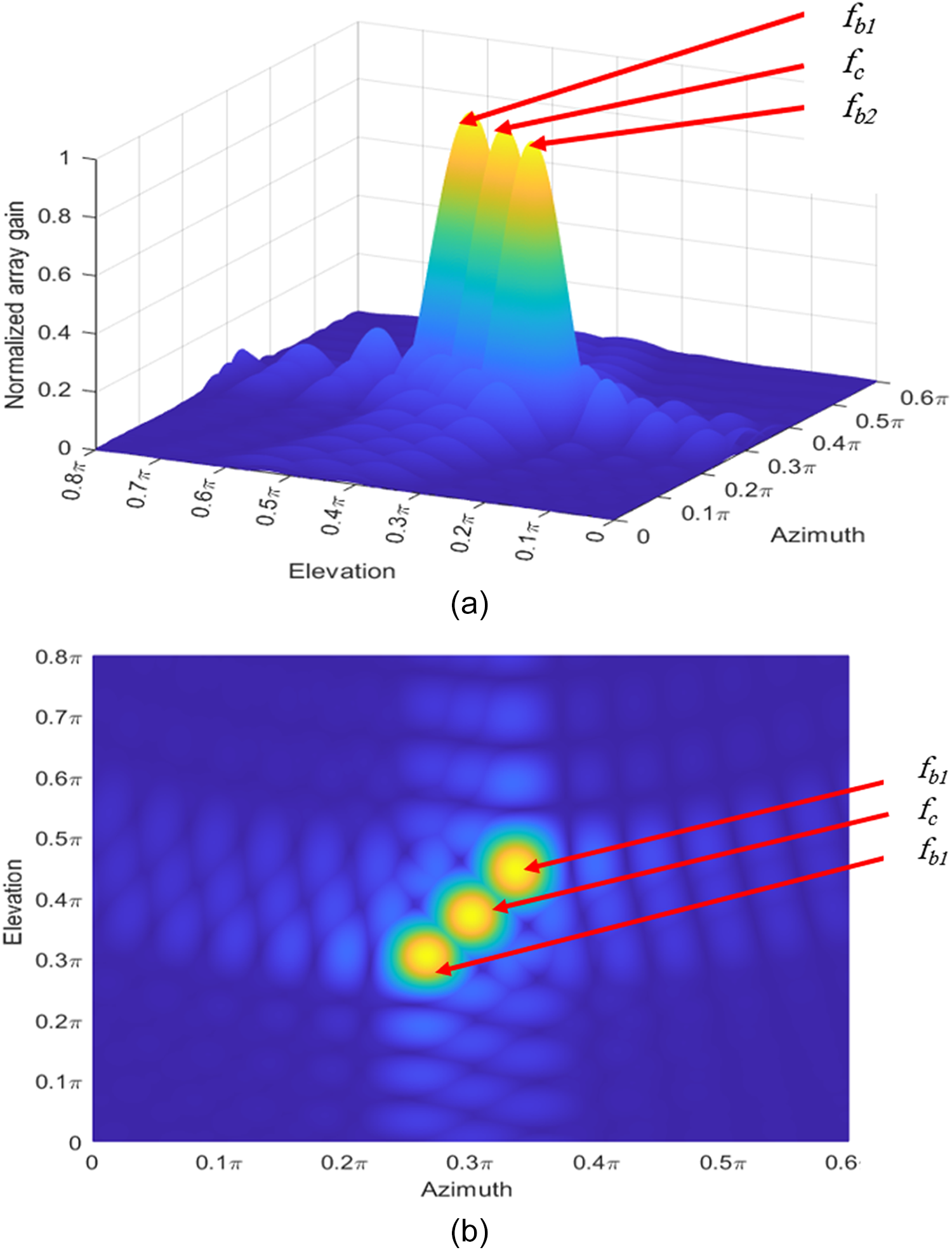
The elevation and azimuth angles were fixed, which present the certain physical directions that result in the maximum array gain. Figure 3a and b illustrates the independent relationships between azimuth angle, elevation angle, and array gain. A reference received beam at the center frequency  ${f_c}$ was used, and compared with the received beam at the other frequencies (
 ${f_{{b_1}}}$and
 ${f_{{b_2}}}$). The boundary of the band beams was found to be severely displaced from the desired direction. In addition, the 3D view in Fig. 4(a) clearly highlights the splitting of the three beams into different directions. Figure 4b shows that the three beams were successfully separated according to the variables of elevation and azimuth angles, as planned.
Array gain vs. (a) azimuth and (b) elevation angles.

Beam splitting at IRS. (a) 3-dimension view (b) an overview from above.

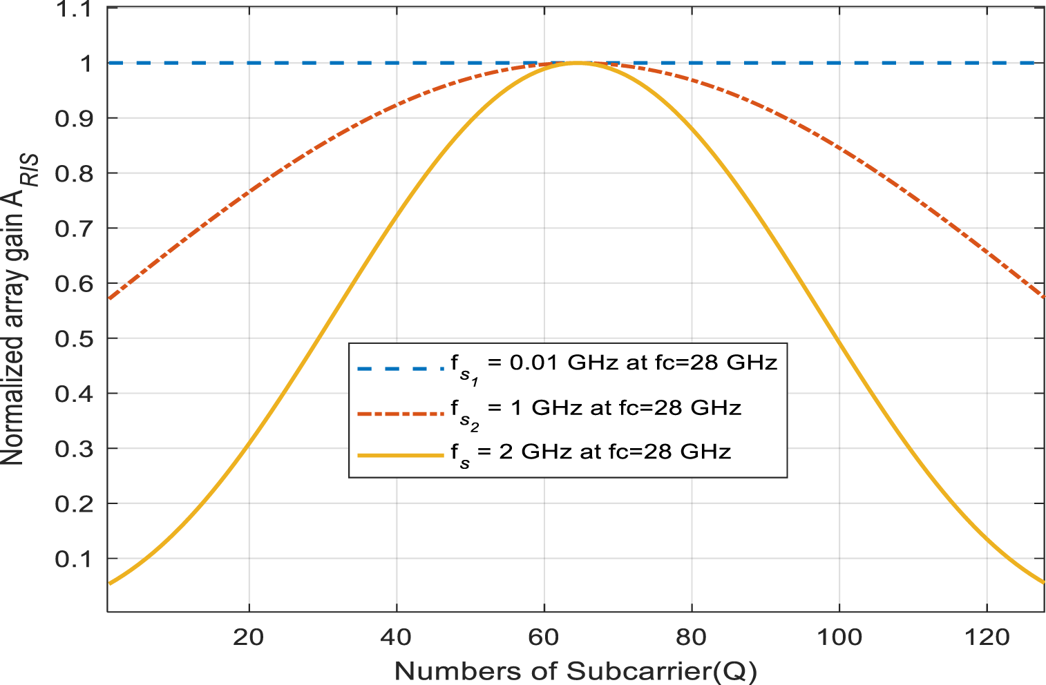
Figure 5 illustrates the relationship between array gain and subcarrier frequency. As more frequencies are used, the array gain is lost. Consequently, having a large bandwidth increase causes an extensive loss in gain, thus decreasing the advantage of employing IRS technology.
Array gain vs. the sub-carrier number for the bandwidths  ${f_{s1}} = 0.01{\text{ }}GHz,{\text{ }}{f_{s1}} = 1{\text{ }}GHz,{\text{ }}and{\text{ }}{f_{s1}} = 2{\text{ }}GHz.$.

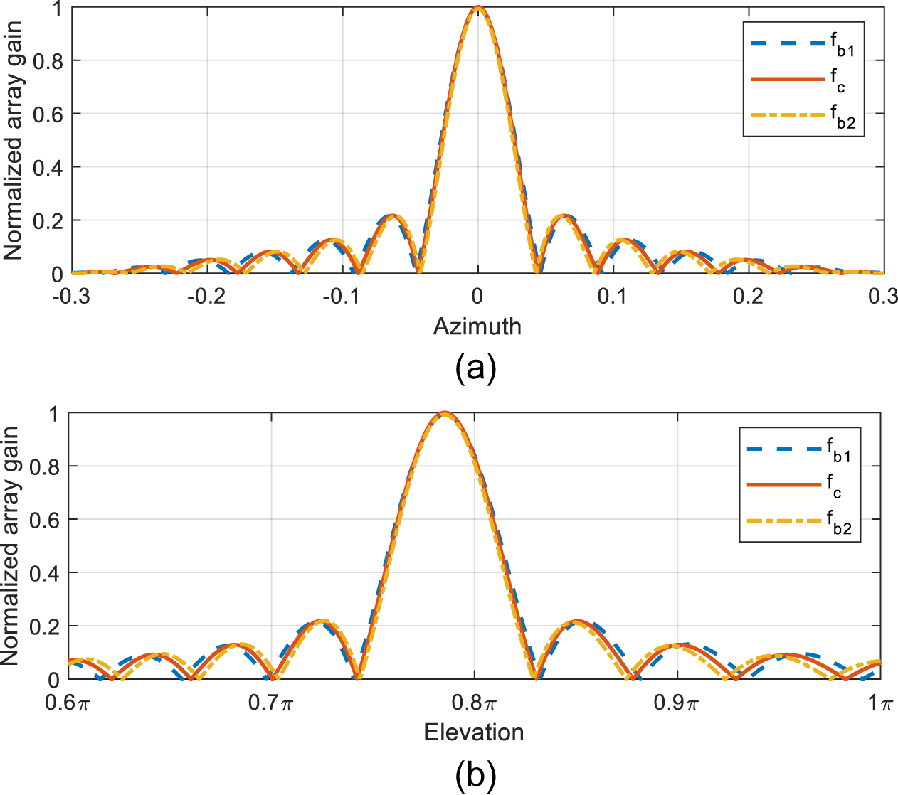
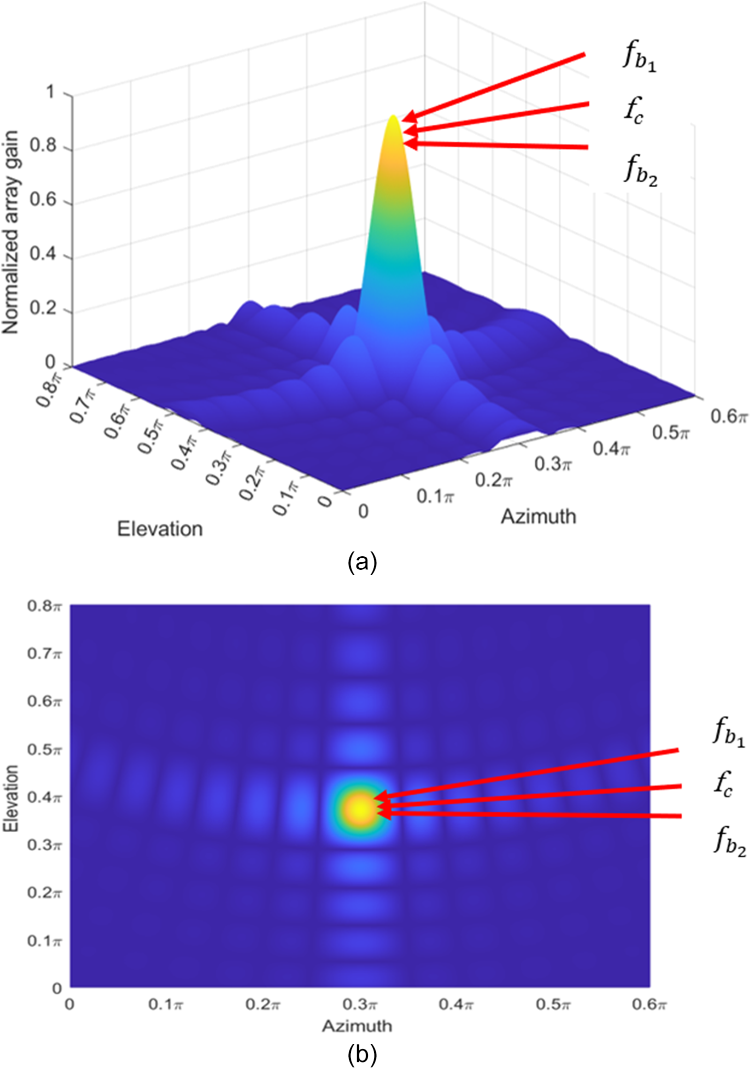
The suggested PTDP system can steer beams produced at different frequencies correctly, as evident from Figs. 6 and 7. The suggested method significantly improves beam alignment to target angles in comparison to the old system with massive gain reduction. This demonstrates that the phase shifters and TD units utilized in the proposed system operate effectively.
Array gain ( $A$) vs (a) azimuth angle and (b) elevation angle for proposed PTDP architecture.

Beams generated using PTDP method:(a) 3D view (b) a bird’s-eye perspective.

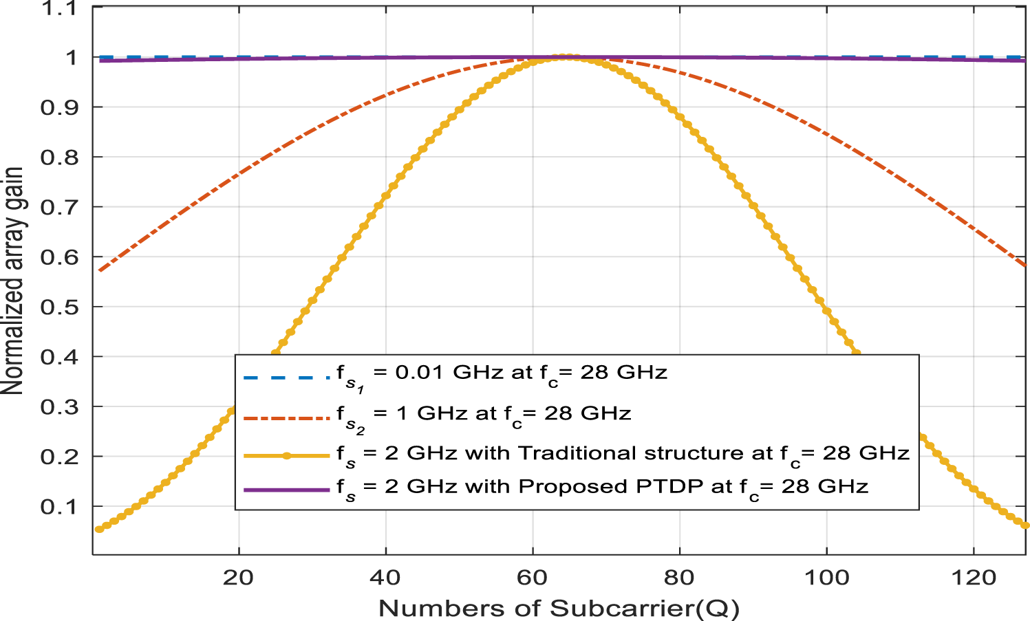
Figure 8 illustrates the normalized array gain versus multiple subcarriers. A comparison of Fig. 8 and Fig. 5 shows that the proposed PTDP and wideband precoding structure effectively eliminates the beam-splitting effect. Specifically, the normalized reduction in array gain is over 82 $\% $ at subcarrier
 $Q = 1$ when used with a narrowband frequency . The results in Fig. 8 show how effective the proposed PTDP design is in solving the beam-splitting issue in IRS systems. The comparison between the performance of the proposed system and the traditional beamforming system for various frequency bands reveals the proposed design provides much greater array gain, particularly in wideband scenarios. The new design improved the gain by 94.5% in comparison to the traditional approach.
The relationship between normalized array gain and number of sub-carriers using proposed PTDP structure.

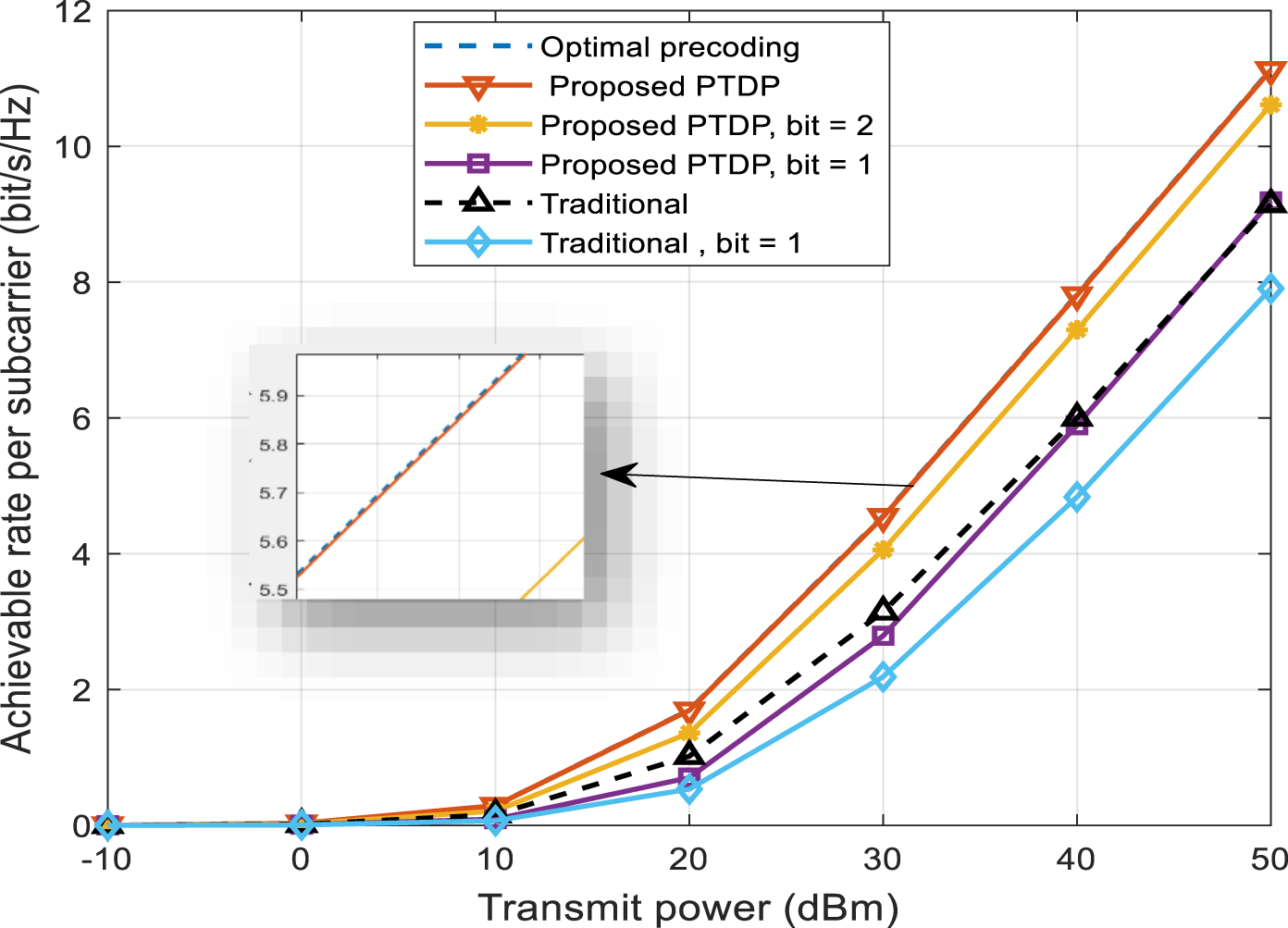
Figure 9 demonstrates the relation between the rate of each subcarrier and the BS’s transmitted power. When every element in the suggested system has a time delay, its frequency-based precoding architecture can reach the best performance. The architecture was based on conventional narrowband beamforming and focused on enhancing phase control performance, which was compared with the conventional design using continuous phase shifting and low-resolution phase shifting (1 and 2 bits) and with the conventional method. The proposed design in this work was also optimized to the best precoding. Conventional narrowband beamforming has been designed using basic phase shift. The proposed PTDP is designed on advanced phase shifting, and considerable performance gain is obtained using these shifts.The result concluded that the data rate is enhanced by 54% at a transmitted power of 30 dBm when the proposed design is employed compared to the conventional design.
Transmitted power vs achievable rate per subcarrier.

The achievable rate for each subcarrier is defined as [Reference Cheng, Huang, Peng, Debbah, Hanzo and Yuen39, Reference Wang, Xiao, Zou, Xie and Liu40]:
 \begin{equation}{R_{optimal}} = \frac{1}{Q} \sum \nolimits_{q = 1}^Q lo{g_2}\left( {1 + \frac{{|{G_q}{|^2}.SNR}}{{{\sigma ^2}}}} \right)\end{equation}
Where the Signal-to-Noise Ratio (SNR):
 \begin{equation}SNR = \frac{{{P_t}}}{{{\sigma ^2}}}\end{equation}
Where the total transmitted power denoted  ${P_t}$, and
 ${\sigma ^2} = - 90dBm$ [Reference Wang, Fang, Yuan, Chen and Li9, Reference Yang, Xie, Lyu, Ning, Zhang and Yuen41].
The continuous precoding achievable rate is expressed as:
 \begin{equation}{R_{con}} = \frac{1}{Q} \sum \nolimits_{q = 1}^Q lo{g_2}\left( {1 + \frac{{|{\Theta _1}{G_q}{\Theta _2}{|^2}SNR}}{{{\sigma ^2}}}} \right)\end{equation}
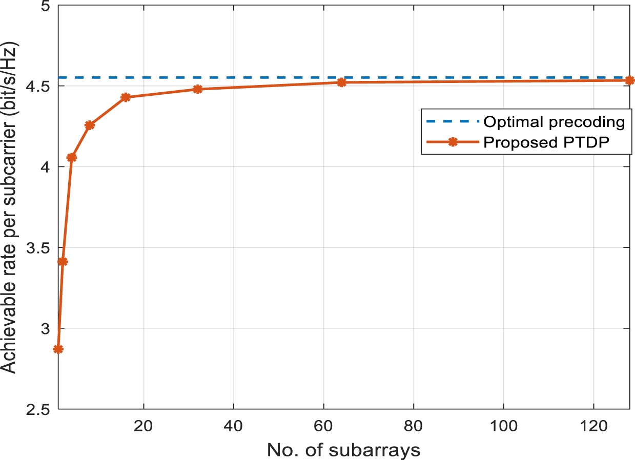
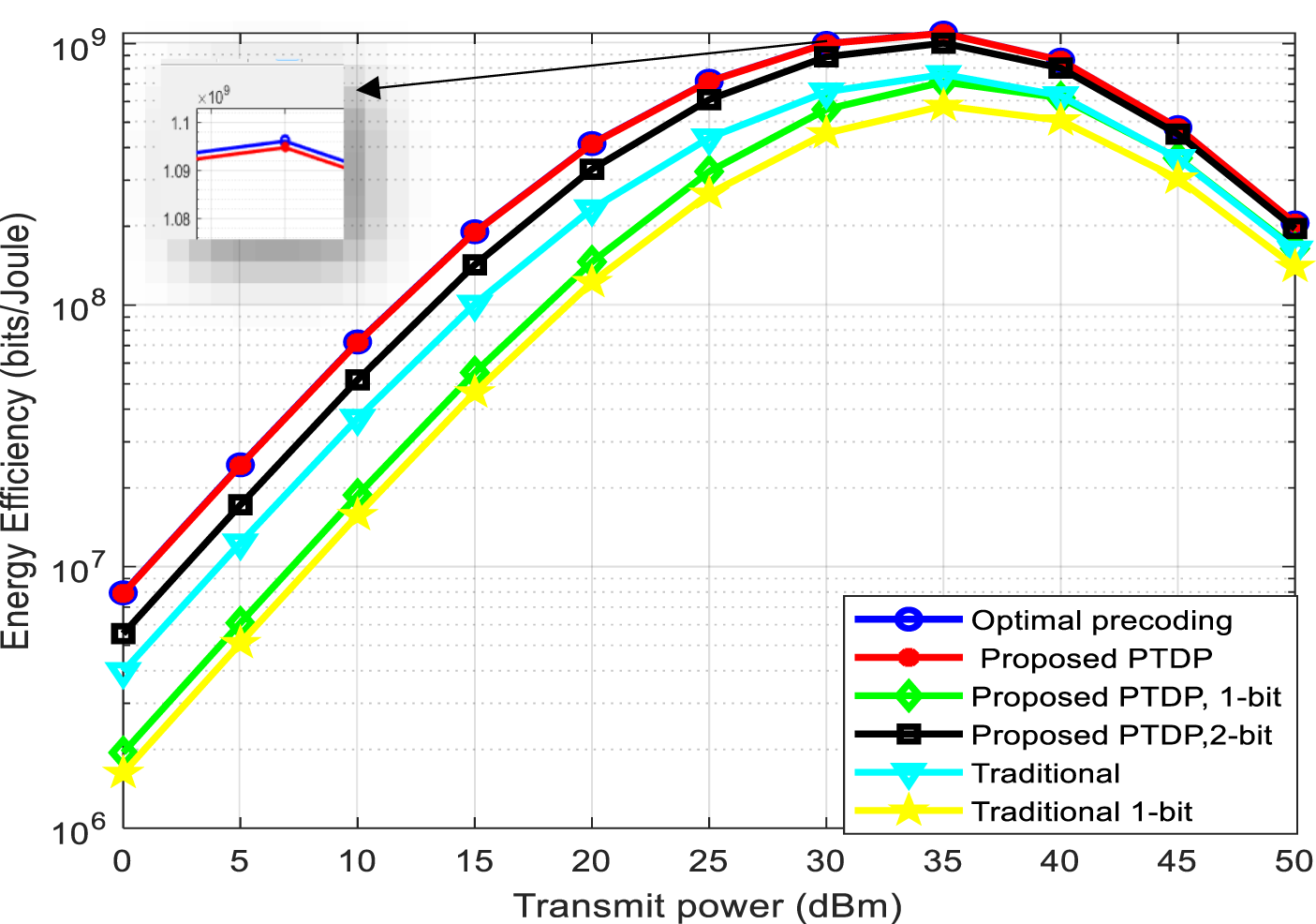
Figure 10 illustrates that with an increase in the number of subarrays, the rate per subcarrier also increases, and as it rises its value is also nearer to ideal precoding. Figure 11 explain the relation between Energy Efficiency and transmited power. Optimal Precoding represents the best possible performance in terms of energy efficiency at different levels of transmission power. The proposed method Proposed PTDP shows a performance close to the optimal but with some differences.
The number of subarrays vs. The achievable rate.

Energy efficiency (bits/joule) vs transmitted power(dbm).

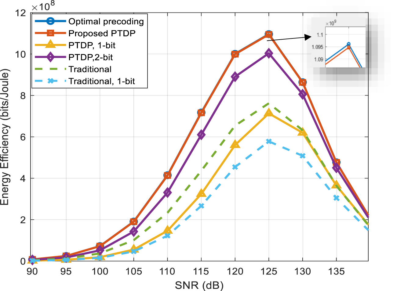
Proposed PTDP with 1-bit, 2-bi refers to the use of a limited-precision digital representation (1-bit, 2-bit) in signal processing. The more bits, the better the performance due to the increased precision of the representation. Traditional and Traditional 1-bi represent the traditional methods with and without using a limited-precision representation. They are usually less efficient than the proposed methods. As the transmited power increases, the energy efficiency of all methods improves due to the improved signal quality. The proposed methods (Proposed PTDP) outperform the traditional methods, especially when using a higher-precision representation (2-bit). Using a limited-precision representation (1-bit) reduces the energy efficiency compared to the higher-precision representation, but it may be beneficial in reducing the computational complexity and energy consumption. It is clear from this that the results show that the proposed methods, especially with increasing representation accuracy, provide better energy efficiency compared to conventional methods, and that increasing transmission power leads to an improvement in overall energy efficiency. Figure 12 shows the relationship between energy efficiency and SNR for different precoding schemes in wireless communication systems. Energy efficiency is measured in bits/joule, which indicates the number of bits that can be transmitted using one joule of energy. Optimal precoding shows the highest energy efficiency across all SNR values, indicating that it is the most energy efficient. The proposed PTDP scheme shows good performance and efficiency close to optimal precoding. The 1-bit and 2-bit PTDP schemes show lower energy efficiency compared to the proposed scheme, indicating that reducing the encoding accuracy negatively affects the efficiency.
Energy efficiency (bits/joule) vs SNR (db).

The traditional scheme shows the lowest energy efficiency, indicating that it is less energy efficient compared to the other schemes.
The energy efficiency was given in below [Reference Huang, Zappone, Alexandropoulos, Debbah and Yuen42]:
 \begin{equation}{\text{Energy Efficiency }}\left( {EE} \right) = \frac{{BW.R{\text{ }}}}{{Total{\text{ }}power}}\end{equation}
Where  $Total{\text{ }}power = {P_{static}} + {P_{IRS}} + {v^{ - 1}}{P_{transmit}}$ [Reference Huang, Zappone, Alexandropoulos, Debbah and Yuen42],
 ${P_{static}} = 4watt$,
 ${P_{IRS}} = {N_1}{N_2}{P_n}$, the element power consumption is
 ${P_n} = 1mw$,
 ${v^{ - 1}} = 1$ [Reference Li, Zhang, Zhu and Dai43], and
 ${P_{transmit}} = 0$ to 50 dBm.
Conclusion
Millimeter wave communication aided by IRS has been faced with the challenge of beam splitting, which results in received signal power loss. In order to combat this problem, phase shift and time delay-based signal precoding schemes have been explored. Building on the beam splitting effect analysis and gain loss analysis, the IRS structure composed of multiple connected layers is proposed. This setup enables the application of a frequency-based and error-tolerant precoding approach for communication channel estimation. The results demonstrate that this approach effectively mitigates the impact of beam splitting, enhancing the efficiency of IRS-assisted mm-wave technology. The proposed PTDP accomplished 94.5% gain improvement over the traditional architecture. In general, it is observed that energy efficiency improves with increasing SNR, but the rate of improvement varies between schemes. The optimal scheme shows the best performance, while the traditional scheme shows the lowest performance. This points out the importance of selecting appropriate precoding schemes to improve the energy efficiency of wireless communication systems.
Competing interest
The authors declare that they have no competing financial interests or personal relationships known to them that could have appeared to influence the work reported in this paper.

Hiba A. Alsawaf Mrs. Hiba earned her B.E. in electrical engineering/electronic and communications engineering from the University of Mosul, Iraq. The same university also awarded her a master’s degree in electronic and communication engineering and she is now working for a PhD in 6G communication. She has taught at Nineveh University’s College of Electronics Engineering for 14 years. She can be contacted at email: hiba.hmdoon@uoninevah.edu.iq

Saad A. Ayoob was born in Ninevah Province, Iraq, in 1972. He received his B.S. degree from the University of Mosul, Iraq, in 1996 and his M.S. degree and Ph.D. from the same University in 2005 and 2011 respectively, both in Communication Engineering. He is currently an Assistant Prof. in the Department of Electrical Engineering, University of Mosul. His research interests include networking, millimeter-wave, 5G, 6G, microstrip patch antenna, Reconfigurable intelligent surfaces (RIS), and communication systems. He can be contacted at email: sa_ah_ay@uomosul.edu.iq