I. INTRODUCTION
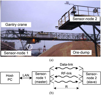
The increasing level of automation in industrial applications calls for a large variety of subsystems such as controllers, handlers, and measurement systems. For the actual problem at hand, the position of a mobile gantry rail crane, depicted in Fig. 1(a), has to be determined for stock inspection of an ore dump. This contribution is an extended version from [Reference Scheiblhofer, Scheiblhofer, Schrattenecker, Vogl and Stelzer1]. Compared with this it discusses the signal model in a more detailed way, offering a simple and effective way of indoor-system calibration. Furthermore, the impact of environmental influences, such as temperature and humidity and their effects on the performance of the system are explained. Therefore, we present a microwave-based ranging technique utilizing the dual-ramp frequency-modulated continuous-wave (DR-FMCW) principle [Reference Stelzer, Jahn and Scheiblhofer2], suitable for operation in harsh environmental conditions such as dust or rough weather. This method has several advantages compared to other available approaches. Optical systems [Reference Rhodes, Myllylä, Peiponen and Priezzhev3] suffer from the influence of diffused light sources and contamination of the focusing lens. Furthermore, focused beams of high-precision laser measurement systems require very accurate adjustment especially in long-range applications and have a limited readout range of several 100 m. Especially for long-range outdoor applications, the global positioning system (GPS) [Reference El-Rabbany4] is another popular approach.
(a) Photograph of the gantry crane system (courtesy of voestalpine AG), (b) system topology of the cooperative DR-FMCW measurement system.

The low-cost implementation of these standard GPS systems is opposed by the limited accuracy of several meters [Reference Drawil, Amar and Basir5], which is undesirable for the application above. A precision of a few centimeters is provided by the differential global positioning system (DGPS) setup, which uses correction data provided by ground-based reference stations at exactly known positions [Reference Tan and Huang6, Reference Adeel, Muaz, Latif and Mahmud7]. The major drawback of DGPS is the dependency on a service provider and the permanent costs for the reception of the correction data. To overcome these disadvantages a cooperative 5.8 GHz radar system is used which is capable of covering distances in the kilometer range with high accuracy. Compared with prior work at 77 GHz [Reference Feger, Pfeffer, Scheiblhofer, Schmid, Lang and Stelzer8] the proposed system in the 5.8 GHz industrial, scientific, and medical (ISM) band offers several advantages. Standard electronic components can be used and there is no need for a special RF-laminate for printed-circuit board design. This keeps the cost and complexity low. Also the possibility to use cables in the range of several meters for connecting the antennas to the system gives additional degrees of freedom to assemble this system in harsh environment. Furthermore, the lower frequency of 5.8 GHz reduces the path loss compared with 77 GHz, increases the maximum measurement range and lowers the effect of damping due to humidity in air.
II. MEASUREMENT PRINCIPLE
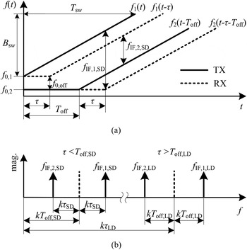
In industrial environments, with multiple reflective objects present, it is demanding for a conventional radar system to identify and track an object of interest. A way to handle this task is to equip the target object at distance R with an active radar transceiver forming a cooperative measurement system. The signal loss between the stations of such a configuration is proportional to R 2, corresponding to the Friis-equation, compared with R 4 for a conventional radar system where the radar-equation is valid. This results in a significantly higher signal-to-noise ratio (SNR) and consequently improves the accuracy, especially for long-distance measurements. One practical implementation uses high-precision temporal synchronization between the stations, realizing an active reflector approach, as presented in [Reference Roehr, Gulden and Vossiek9]. Here only the measurement data at one station has to be evaluated but the achievable accuracy highly depends on the quality of the synchronization, which has to be in the picosecond range. A different approach to distance estimation, which is applied in the presented system, combines the acquired data using a data-link between the stations as shown in Fig. 1(b). The DR-FMCW approach is based on the classical frequency-modulated continuous-wave (FMCW) radar principle [Reference Stove10] using linear frequency sweeps f i (t) with identical chirp-rates k = B sw/T sw at each ith station. The sweep bandwidth B sw is covered within the ramp-duration T sw, depicted in Fig. 2(a).
(a) Frequency chirps of the DR-FMCW cooperative radar, (b) magnitude spectra of the obtained IF for short distance and long distance measurement mode.

The starting frequencies f 0, i are not inherently equal. After a predefined coarse temporal pre-synchronization in the μs range station one immediately starts to transmit its chirp, which is received at station two after the additional time-of-flight (TOF) τ. The start of the sweep at the second station is delayed by the adjustable parameter T off. The transmit (TX) signal from each station is down-converted with the receive (RX) signal from the other station. With the identity f 0,1 − f 0,2 = f 0, off the intermediate frequency (IF) frequencies f IF , i
 $$f_{{\rm IF}\comma 1\comma \rm SD}=k\lpar {T_{\rm off}+\tau_{\rm SD} } \rpar +f_{0\comma \rm off}\comma \; $$
 $$f_{{\rm IF}\comma 2\comma {\rm SD}}=k\lpar {T_{\rm off} - \tau_{\rm SD} } \rpar +f_{0 \comma {\rm off}}\comma \; $$
 $$f_{{\rm IF}\comma 1\comma {\rm LD}}=k\lpar {T_{\rm off}+\tau_{\rm LD} } \rpar +f_{0\comma \rm off}\comma \; $$
 $$f_{{\rm IF}\comma 2\comma \rm LD}=k\lpar { - T_{\rm off}+\tau_{\rm LD} } \rpar - f_{0\comma \rm off}\comma \; $$
can be obtained. Note that by selection of T off the DR-FMCW system can be operated in two measurement modes, denoted as short distance (SD) mode, where τ SD < T off is valid, and a long distance (LD) mode for τ LD > T off. Figure 2(b) schematically shows the corresponding frequency spectra for both measurement modes. At the SD mode the IF signals are centered at kT off, in comparison with kτ LD in the LD mode. This obviously reduces the requirements on the system's sampling rate at high distances. Via the data-link the f IF , i results are exchanged between the stations and combined in the following signal processing step. This leads to
 $$f_{\rm IF\comma SD}=f_{\rm IF\comma 1\comma SD} - f_{\rm IF\comma 2\comma SD}=2k\tau _{\rm SD}\comma \; $$
 $$f_{\rm IF\comma LD}=f_{\rm IF\comma 1\comma LD}+f_{\rm IF\comma 2\comma LD}=2k\tau _{\rm LD}\comma \; $$
which is converted to a distance estimate by R = τc with c the propagation velocity of the electromagnetic wave. Note that the parameters T off and f 0, off are eliminated. The only criterion that has to be fulfilled from these parameters are that the single-station's IF frequencies f IF , i do not violate the Nyquist-criterion. Furthermore, as shown in [Reference Scheiblhofer, Schuster, Jahn, Feger and Stelzer11], the combined evaluation of the data sets strongly reduces the phase-noise impact. This is a significant advantage to the time-synchronized approach [Reference Roehr, Gulden and Vossiek9], where uncorrelated phase-noise especially at shorter ranges has a degrading effect on accuracy.
III. SENSOR-NODE AND SYSTEM TOPOLOGY
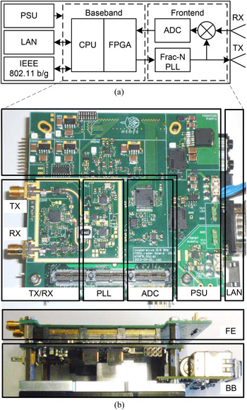
The main components of the presented system's sensor-nodes are the radar frontend (FE) and baseband board (BB), depicted in Fig. 3. The FE consists of a low noise 5.8 GHz voltage-controlled oscillator (VCO) controlled by an integrated fractional-N synthesizer, which itself is driven by an reference oscillator. A voltage-controlled crystal oscillator (VCXO) at a nominal frequency of f ref = 100 MHz with good phase-noise performance of −164 dBc/Hz at 100 kHz is used. For conformity with the ISM band regulation it is ensured that the equivalent isotropically radiated power (EIRP) including the additional gain of the used TX antenna is limited to 25 mW. The RX signal, received from the opposing unit is bandpass filtered, amplified, and fed to the mixer. A 14-bit analog-to-digital converter (ADC) providing a maximum SNR of 80 dB is used for digitizing the IF signal after low-pass filtering. In this application, the local oscillator (LO) signal is intended to be mixed with the time-delayed TX signal of the other station only. To reduce parasitic echoes caused by crosstalk of the TX signal a dual-antenna setup was realized, where TX and RX antennas are mounted with orthogonal polarization planes.
(a) Block diagram of a single sensor-node. (b) top and side-view photograph of the FE printed circuit board, stacked onto the baseband board. The overall dimensions are 100 × 105 × 40 mm3.

As BB processors an Intel® Atom™ CPU combined with an Arria® GX2 FPGA on a single socket are used. The CPU operates a Linux system under general public license and the on-board signal processing engine is based on Octave. A host-PC is used as man–machine interface and allows the configuration of the measurement setup, data evaluation, and displays the measurement results. The host-PC connects to the first node (master) via a Gb-Ethernet connection. This specific node additionally runs an access point for the remotely connected measurement stations (slaves). The data-link between these stations is realized by an IEEE 802.11 b/g link, which provides a transmission rate up to 54 MBit/s and flexible encryption options. Depending on the configuration the on-board signal processing engine either performs frequency estimation using Fourier-transform with additional chirp-z transform and parabola interpolation techniques or transmits compressed raw datasets via the radio link. As every sensor-node is remotely accessible from the host-PC it is possible to modify or exchange the files, including the system software as well as the signal-processing sources. This is an advantage concerning maintainability of the whole measurement setup providing the user with maximum flexibility of the software system. The system can be extended to multiple slave-stations, as every sensor-node is equipped with a unique address for explicit identification. This enables the system to perform measurements between selected pairs of sensor-nodes in a time-division approach, relaxing the requirements on slant range resolution. The block diagram of the measurement system is shown in Fig. 3(a).
IV. ENVIRONMENTAL EFFECTS ON RANGING ACCURACY
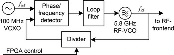
The presented measurement system is used in an outdoor environment. Here especially the impact of temperature on the phase-locked loop (PLL) circuit used for generation of the radio frequency (RF) signal has to be taken into account. A PLL itself is a feedback-system used to control the output frequency of an RF-VCO, as depicted in Fig. 4 [Reference Banerjee12]. The RF-frequency, generated by the VCO is scaled down by a programmable divider and fed to the phase–frequency detector (PFD). The second input is driven by the reference VCXO. The PFD compares both signals and generates a control signal to tune the RF-VCO until both inputs are equal in phase and frequency. The loopfilter in between PFD and RF-VCO performs the current-to-voltage conversion, filtering the tuning signal, and stabilizes the closed-loop PLL.
Schematic of a basic PLL-feedback system.

A) Influence of temperature on the measurement hardware
Apparently a deviation of the reference frequency f ref from its nominal value by a factor α directly influences the output frequency f RF according to
 $$\Delta f_{\rm ref}=\lpar \alpha - 1\rpar f_{\rm ref}\comma \; $$
 $$\Delta f_{\rm RF}=\lpar {\alpha - 1} \rpar f_{\rm RF} .$$
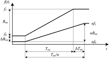
The start-frequency f 0, stop-frequency f 1, and sweep bandwidth B sw directly scale with the deviation factor α as well. As the reference clock furthermore is the temporal basis of the FMCW-ramp, it additionally influences the ramp-duration T sw. The chirp-rate k therefore is affected by both effects, the variation of B sw and T sw, as depicted in Fig. 5, where an exemplary deviation factor α < 1 reduces the bandwidth and increase the ramp-duration of the frequency chirp. The following formulas summarize the overall effect on the ramp-parameters:
 $$\Delta f_0=\lpar \alpha - 1\rpar f_0\comma \; $$
 $$\Delta f_1=\lpar \alpha - 1\rpar f_1\comma \; $$
 $$\Delta B_{\rm sw}=\lpar \alpha - 1\rpar B_{\rm sw}\comma \; $$
 $$\Delta T_{\rm sw}=\left({\displaystyle{1 \over \alpha } - 1} \right)T_{\rm sw}\comma \; $$
 $$\Delta k=\lpar \alpha ^2 - 1\rpar k.$$
Effect on a linear FMCW-ramp caused by deviation of reference frequency.

As a consequence any uncompensated offset of the reference frequency is a reason for bias in the distance measurement. To improve the accuracy of the ranging results these deviations can be considered in the signal model. From the classical phase terms of the FMCW TX signal [Reference Stove10]
 $$\varphi _{\rm TX} \lpar t\rpar =2\pi \left({\left({f_0+\displaystyle{k \over 2}t} \right)t} \right)+\varphi _0\comma \; $$
where φ 0 is the initial phase-offset, an extended signal model can be derived. Therefore (14) is extended by the time-offset T off , i and deviation factors α i , with station index i to
 $$\varphi_{{\rm TX}\comma{\rm i}} \lpar t\rpar =2\pi \left({\alpha_{\rm i} f_{{\rm 0}\comma {\rm i}} \lpar {t - T_{{\rm off}\comma i} } \rpar +\alpha_i^2 \displaystyle{k \over 2}\lpar {t - T_{{\rm off}\comma i} } \rpar^2 } \right) + \varphi_0 \comma{\rm i}.$$
Considering the TOF τ and different deviation factors for each station the down-converted phase of the IF signals of both stations can be calculated to
 $$\eqalign{\varphi _{{\rm IF}\comma 1} \big( t \big) &= 2\pi \Big(f_0 t \big( {\alpha_1 - \alpha_2 } \big) \cr &\quad + \displaystyle{{kt^2} \over 2} \big( \alpha_1^2 - \alpha_2^2 \big) {\,+\,kt\alpha_2^2 T_{{\rm off}\comma \rm S}+\alpha_2^2 kt\tau } \Big) } $$
and
 $$\eqalign{\varphi _{{\rm IF}\comma 2} \lpar t\rpar & = 2\pi \Big( \!\!- f_0 t\lpar {\alpha_1 - \alpha_2 } \rpar \cr&\quad -{\displaystyle{kt^2 } \over 2}\lpar {\alpha_1^2 - \alpha_2^2 } \rpar - kt\alpha_2^2 T_{{\rm off}\comma \rm S}+\alpha_1^2 kt\tau \Big) }. $$
The combined evaluation of these terms leads to the range-proportional frequency f IF and distance R
 $$f_{\rm IF} \lpar \alpha _{1\comma 2} \rpar =k\tau \lpar {\alpha_1^2+\alpha_2^2 } \rpar \comma \; $$
 $$R\lpar \alpha _{1\comma 2} \rpar =\displaystyle{{f_{\rm IF} c} \over {k\lpar {\alpha_1^2+\alpha_2^2 } \rpar }}\comma \; $$
where in the ideal case of α i = 1 the same results as in (5) are valid. Same as before f 0, off and T off are eliminated. The distance offset is only dependent on the α i factors, which modify the nominal chirp-rate k. The resulting offsets of the IF frequency and therefore the distance bias ΔR can be calculated as follows
 $$\Delta f_{\rm IF} \lpar \alpha _{1\comma 2} \rpar =k\tau \,\,\lpar {\alpha_1^2+\alpha_2^2 - 2} \rpar \comma \; $$
 $$\Delta R\lpar \alpha _{1\comma 2} \rpar =\displaystyle{{f_{\rm IF} c\lpar {2 - \alpha_1^2 - \alpha_2^2 } \rpar } \over {2k\lpar {\alpha_1^2+\alpha_2^2 } \rpar }}.$$
B) System calibration
In the real-world hardware-setup the issue of α ≠ 1, thus a deviation of the nominal reference frequency is typically caused by production tolerance of the reference quartz crystals. Typical quartz crystals for standard industrial applications exhibit a static frequency offset of ±20 ppm to ±50 ppm. Commonly, in case of unknown α, in-field calibration measurements have to be conducted. Both stations have to be installed on site and different distances have to be measured and compared with accurate reference measurements. With this method it is difficult to achieve a good calibration quality due to temperature and multipath effects.
Using the extended signal model (19) this outdoor calibrations can be substituted. Therefore the static frequency offset is determined off site using a frequency-counter in an indoor environment with well defined and reproducible ambient conditions. Furthermore every station can be characterized by its own without the need for a fully operative measurement setup. The obtained calibration values are stored directly on the sensor nodes. Note that the same approach can be applied to calibrate the sampling frequency of the ADC, especially if it is generated by a separate oscillator.
V. SIMULATION AND MEASUREMENT RESULTS
As part of the system characterization the theoretical robustness of the DR-FMCW approach against variation of T off and Δf 0 – as stated in (5) – was investigated based on laboratory measurements in comparison with simulation results.
A) Simulations
The cooperative radar simulator is based on the signal model (15), where phase-noise components introduced by the system's VCO are modeled by φ PN , i (t).
 $$\eqalign{\varphi_{{\rm TX}\comma {\rm PN}\comma i} \lpar t \rpar = & 2 \pi \left({\alpha_{\rm i}f_{{\rm 0}\comma {\rm i}} \lpar {t - T_{{\rm off}\comma {\rm i}} }\rpar + \alpha_i^2 \displaystyle{k \over 2}\lpar {t - T_{{\rm off}\comma {\rm i}} } \rpar^2 } \right) \cr & + \varphi _{{\rm 0}\comma {\rm i}}+\varphi_{{\rm PN}\comma {\rm i}} \lpar t \rpar.}$$
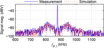
The starting frequencies f 0, i, the chirp-rates k, as well as the deviation factors α i are used as simulation parameters. The fixed additive white Gaussian noise level and the PLL-shaped phase-noise densities were determined by characterization of the FE's hardware components and integrated into the model according to the simulation approach presented in [Reference Scheiblhofer, Treml, Schuster, Feger and Stelzer13]. An exemplary comparison between the IF signal from a cooperative measurement at a single station and its synthetical, simulator-generated pendant is shown in Fig. 6.
An exemplary comparison of the IF spectrums of a measured signal with a signal gained by the radar simulator using identical settings.

B) Indoor measurements
In the laboratory environment the TX and RX ports of the sensor-nodes have been connected by microwave cables to establish a reproducible measurement scenario. The path loss was simulated by attenuators at the TX port to limit the IF signal power to −40 dBm, which is equivalent to the received power at a free-space distance of about 15 m.
1) EFFECT OF T OFF AND F 0, OFF
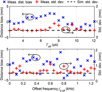
Parameter sweeps of T off and f 0, off have been performed to investigate the influence on the distance bias. To avoid confusion with reference frequency offsets in this step the reference oscillators have been tuned to their nominal values, so α i = 1 can be assumed. To maintain comparability the measured distance bias was calculated from a reference measurement at T off = 4 µs, which was also used as standard delay at the short-distance outdoor measurements afterwards. At the measurement investigating the influence of f 0, off the PLL of the second sensor-node was programmed to start the frequency sweep at f 0,2 = f 0,1 −f 0, off and stop at f 1,2 = f 1,1 − f 0, off, with identical settings of the ramp duration. This ensures that chirps of both stations are covering the same bandwidth. The results of both parameter sweeps are depicted in Fig. 7 and compared with Monte Carlo simulations with 2000 trials at each measurement point. The distance bias is below ±5 mm with approximately zero mean across the parameter sweep, as expected from the signal model. The standard deviation is in the sub-millimeter range and in very good agreement with the simulation results. This verifies that the signal model accurately describes the real-world hardware realization, especially with respect to sweep linearity.
Bias of distance and standard deviation due to different offset times T off and decreasing starting frequency f 0,2 of the second sensor-node determined by the setup in the laboratory. The measurement results are in good agreement with the simulated standard deviation.

2) EFFECT OF REFERENCE FREQUENCY OFFSET
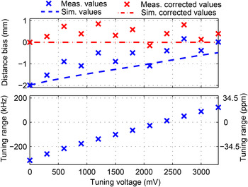
To show the effectiveness of the distance correction procedure described in Section V-B), the same indoor measurement setup was used with minor modifications. To simulate the static frequency offset the reference VCXO of station one is tuned by an external source. The resulting frequency deviation of the tuned station can be seen in the bottom part of Fig. 8. In the upper part of the same figure the measured and simulated ranging bias for different tuning voltages is depicted and compared with the results based on (19). As can be seen, by considering the individual deviation factors α i the bias can be reduced significantly. Assuming a ±40 ppm standard industrial crystal oscillator with an output frequency of f ref = 100 MHz, this would lead to a distance offset of about ±2 mm. Note that this offset scales linearly with range, thus at a distance of 1000 m the bias would increase to more than 100 mm. The frequency offset of the reference oscillators is therefore a significant source of inaccuracy, especially for the long-range application at hand.
Top: Measurement results and simulation of a wired test-setup with and without consideration of the correction factors α. Bottom: The deviation of station 1 with respect to 5.8 GHz by tuning of the reference oscillator to achieve different tuning slopes.

3) EFFECTS OF TEMPERATURE CHANGE
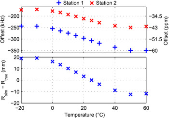
To investigate the influence of the external environmental temperature measurements in a climate cabinet were conducted. Both stations were exposed to temperatures between −20°C to +60°C, which covers and exceeds the overall temperature conditions at the industrial site. To ensure comparable results the tuning-input of the reference VCXO was set to ground potential and relative humidity within the cabinet was set to 30%. The results of the measurements are depicted in Fig. 9. It can be seen, that the actual frequency of both reference clocks differs from their nominal frequencies. Owing to the grounded tuning input pin the oscillator's output is pulled to the lowest possible frequency, resulting in a negative offset with reference to the desired 5.8 GHz. For the presented system the static frequency offset has significantly higher impact than the temperature drift, if both stations are exposed to similar ambient temperatures. It is therefore sufficient to use α i factors at a defined calibration temperature of T cal = 25°C for the compensation of the distance bias. The impact of the temperature-drift on the distance bias is also shown in the bottom part of Fig. 9. Over the whole temperature range the calculated error lies below ±20 mm.
Top: RF frequency offset at 5.8 GHz caused by change of environmental temperature, measured in a climate cabinet. Bottom: The resulting simulated distance error caused by the temperature drift at 1000 m.

4) EFFECTS OF TEMPERATURE, DRY AIR PRESSURE, AND HUMIDITY
Although often neglected it is essential to use the correct value of the propagation velocity of the electromagnetic wave in the corresponding medium in contrast to vacuum. Otherwise an additional range-dependent error would be introduced. The propagation velocity in air varies with the parameters like temperature, barometric pressure, and humidity. The effects of these parameters have minor influence in most short-ranged radar applications. Nevertheless, for applications in the kilometer range the variation of the environmental conditions can result in significant distance deviations up to several cm. The calibration was conducted at temperature T cal = 25°C and a standard absolute dry air pressure of p cal = 103.25 kPa at sea-level. This results in a propagation velocity of c = 299704442 m/s. This velocity can be calculated applying the refraction index n of the electromagnetic wave [Reference Jursa14]
 $$n=1+77.6 \cdot 10^{ - 5} \displaystyle{p \over T}+0.373\displaystyle{{p_{\rm wv} } \over {T^2 }}\comma \; $$
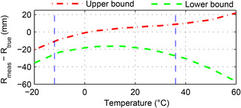
where T denotes the temperature in degrees Kelvin, p the pressure in kPa and p wv the partial pressure of water vapor in kPa. With c = c 0/n, where c 0 is the propagation velocity of the electromagnetic wave in vacuum, the corresponding velocity in air can be derived. For the simulation of the distance error, caused by a variation of c, pressure boundary values between 98.7 kPa and 103.8 kPa and relative humidity between 0 and 100% have been used. This data has been taken from [15] for the year 2013, in which the outdoor measurements have been carried out and for the region where the gantry crane is located. While the increasing propagation velocity at higher temperatures leads to undervalued distance measurements, the inverted characteristic of the temperature drift of the reference oscillators softens the resulting error. The sum of this effects at a distance of 1000 m is depicted in Fig. 10 where a upper and lower bound distance offset is given. The upper bound is defined by the maximum pressure and humidity whereas the lower bound is in scenarios with dry air and minimum pressure. It can be seen, that the expected distance error due to the investigated effects between the measured minimum of −12°C to the maximum of +36°C at the measurement location is below ±28 mm.
C) Gantry rail crane measurements
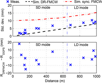
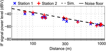
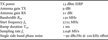
In the industrial scenario, one sensor-node (slave) has been mounted on a service platform at the far end of the operational gantry rail crane site. The other node (master) and the host-PC were installed at the moving crane beam as shown in Fig. 1(a). At each distance 500 measurements were acquired using a defined system setup summarized in Table 1. The maximum possible distance that can be covered in SD mode is 1024 m, assuming that T off perfectly centers the IF frequencies around a quarter of the sampling rate. To avoid the signals being corrupted by DC-leakage or violating the Nyquist-criterion the LD measurement mode was used at distances above 650 m. Reference range measurements were carried out with a DGPS receiver (Leica Geosystems™ CS10 with Leica™ Viva antenna). The accuracy of the used reference measurement setup is given with 5 mm [16]. A single calibration measurement was used to estimate the constant distance offset. As in Section V-B) 2000 Monte Carlo trials at distance steps of 50 m were carried out to compare the ranging results with simulations. At each individual distance point the signal amplitude varied accordingly. The measurement results in Fig. 11 show that the standard deviation of the DR-FMCW system never exceeds 12 mm over the whole distance range. The distance error, determined by the deviation between the DGPS and DR-FMCW is in the range of ±20 mm. This result underlines the effectiveness of the applied indoor calibration process of the sensor-nodes. The measurement results are in good agreement with the simulated standard deviations. For comparison purposes the radar simulator was used to determine the theoretical achievable standard deviations of the synchronized measurement approach without data exchange, assuming an optimal time-synchronization of the given stations. Owing to the phase-noise correlation and averaging effects [Reference Scheiblhofer, Treml, Schuster, Feger and Stelzer13] the DR-FMCW system results in a significantly better performance than the perfectly synchronized approach, especially at low distances. Analyzing the measured signal power levels depicted in Fig. 12, the maximum operational range is calculated up to 5000 m, with an SNR margin of approximately 10 dB.
Minimum and maximum distance bias at R = 1000 m. The propagation velocity depends on temperature, pressure, and humidity of air. The upper bound is determined by maximum pressure and humidity, whereas the lower bound by dry air and minimum pressure. The vertical lines are marking the lowest and the highest measured temperatures of −12°C to +36°C in the year 2013 for the measurement location.

Top: measured and simulated standard deviation of the DR-FMCW system in the gantry rail crane application compared with the perfectly synchronized approach. Bottom: range deviation compared with a DGPS receiver.

Measured and calculated signal power level of the DR-FMCW measurement system in the gantry rail crane application with the systems noise floor.

System- and measurement parameters

VI. CONCLUSION
In this paper, we presented the successful implementation of the DR-FMCW radar system capable to operate in harsh industrial environment. The application at hand incorporates roughly time-synchronized and fully remotely controlled sensor-nodes to determine the position of a gantry crane at an ore dump with high accuracy. Laboratory measurements were carried out to prove the robustness of the developed hardware against synchronization and offset-frequency imperfections. Additionally an effective and easy way for indoor-calibration of reference frequency offsets has been depicted, and the impact of different environmental conditions have been shown. The system provides a standard deviation lower than 12 mm for range estimation at distances up to 1000 m. Considering the industrial environment scenario this points out the excellent performance of the used measurement principle. The estimation results were verified with a commercially available DGPS system and are in good agreement with the outcomes from simulations. With this DR-FMCW concept it is possible to extend the system's range to multiple kilometers.
ACKNOWLEDGEMENTS
The authors acknowledge the voestalpine AG for providing support and access to the gantry crane system as well as the DK Vermessungsservice ZT-GmbH for assistance at the crane measurements and providing reference measurement data. This work has been supported by the Linz Center of Mechatronics (LCM) in the framework of the Austrian COMET-K2 program.
 Werner Scheiblhofer was born in Linz, Austria in 1982. He received his Dipl.-Ing. (M.Sc.) degree in Mechatronics from the Johannes Kepler University, Linz, Austria in 2009. In the same year, he joined the Institute for Communications Engineering and RF-Systems, Johannes Kepler University as Research Assistant. His research topics are radar system design and concepts for industrial radar sensors.
 Stefan Scheiblhofer was born in Linz, Austria, in 1979. He received his Dipl.-Ing. (M.Sc.) degree in Mechatronics and Ph.D. in Mechatronics from Johannes Kepler University, Linz, Austria, in 2003 and 2007, respectively. Until 2010 he was with the Christian Doppler Laboratory for Integrated Radar Sensors, Institute for Communications and Information Engineering, Johannes Kepler University. His primary research interests concern advanced radar system concepts, development of radar signal processing algorithms, statistical signal processing, RF design, and its application to automotive radar applications. Currently he is with Hainzl industrial systems in Linz.
 Jochen O. Schrattenecker was born in Wels, Austria, in 1985. He received his Dipl.-Ing. (M.Sc.) degree in Mechatronics from Johannes Kepler University, Linz, Austria in 2011, and is currently working toward the Ph.D. degree at Johannes Kepler University. In 2011, he joined the Institute for Communications Engineering and RF-Systems, Johannes Kepler University, as a Research Assistant. His research topics are radar signal processing, as well as radar system design for industrial sensors.
 Simon Vogl is heading a systems design office developing embedded system solutions in industry and health fields. He has spent several years as a researcher in the fields of Pervasive Computing and Multimedia systems, closing the gap between sensors, embedded systems, and user interfaces.
 Andreas Stelzer received his Diploma Engineer degree in Electrical Engineering from the Technical University of Vienna, Vienna, Austria, in 1994, and Ph.D. in mechatronics (with honors sub auspiciis praesidentis rei publicae) from the Johannes Kepler University Linz, Austria, in 2000. In 2003, he became an Associate Professor with the Institute for Communications Engineering and RF Systems, Johannes Kepler University Linz. Since 2008, he has been a key researcher for the Austrian Center of Competence in Mechatronics (ACCM), where he is responsible for numerous industrial projects. Since 2007, he has been Head of the Christian Doppler Research Laboratory for Integrated Radar Sensors, and since 2011 he is full Professor at the Johannes Kepler University Linz, heading the Department for RF-Systems. He has authored or coauthored over 320 journal and conference papers. His research is focused on microwave sensor systems for industrial and automotive applications, radar concepts, SiGe-based circuit design, microwave packaging in eWLB, RF and microwave subsystems, surface acoustic wave (SAW) sensor systems and applications, as well as digital signal processing for sensor signal evaluation. Dr. Stelzer is a member of the Austrian ÖVE. He has served as an associate editor for the IEEE MICROWAVE AND WIRELESS COMPONENTS LETTERS. Currently, he serves as Co-Chair for MTT-27 Wireless-Enabled Automotive and Vehicular Applications. He was the recipient of several awards including the 2008 IEEE Microwave Theory and Techniques Society (IEEE MTT-S) Outstanding Young Engineer Award and the 2011 IEEE Microwave Prize, 2012 European Conference on Antennas and Propagation (EuCAP) Best Measurement Paper Prize, the 2012 Asia Pacific Conference on Antennas and Propagation (APCAP) Best Paper Award, the 2011 German Microwave Conference (GeMiC) Best Paper Award, the EEEfCOM Innovation Award, and the European Microwave Association (EuMA) Radar Prize of the European Radar Conference (EuRAD) 2003. He is a member of the IEEE MTT, IM, and CAS Societies and is serving as IEEE Distinguished Microwave Lecturer since 2014.