I. INTRODUCTION
Both experimental and theoretical studiesReference Vandyoussefi, Kerr and Kurz1–Reference Wang and Wei5 have been carried out on peritectic solidification since many technologically important materials have been observed in peritectic systems. Recently, many studies on peritectic solidification have been carried out, and complex microstructures have been obtained, such as the dendritic/cellular growth of primary phase in the matrix of peritectic phase, coupled growth,Reference Trivedi and Park6, Reference Boettinger7 and banded structure.Reference Li, Ng and Jones8–Reference Ma, Li, Ng and Jones10 In the presence of steep temperature gradients, if the dendrite is held in the mushy zone for some time, the migration of secondary dendrite arms occurs.Reference Liu, Li, Su, Peng, Guo and Fu11
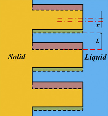
The migration of secondary dendrite arm along the primary stem toward the dendrite tips has been observed in many alloys.Reference Liu, Li, Su, Peng, Guo and Fu11–Reference Allen and Hunt17 As shown in Fig. 1, the opposite sides of the liquid pool between adjacent secondary dendrite arms are located at different temperatures and therefore have different solute compositions due to local thermodynamic equilibrium at the solid/melt interface. Hence, according to the temperature gradient zone melting (TGZM) theory,Reference Pfann18 continuous-coupled remelting (at the hot side) and solidification (at the cold side) of the liquid pool (with a length of L) occur between two adjacent secondary arms. The solid lines and dashed lines represent the positions of the secondary dendrite arms before and after the remelting/solidification process, respectively. The distance the secondary dendrite arm migrates upward is x. During peritectic solidification, the feature of the migration of secondary dendrite arm is that the remelting interface of primary phase and the solidification (growth) interface of peritectic phase are located at different temperatures.Reference Liu, Li, Su, Peng, Guo and Fu11 This migration proceeds via diffusion through the liquid phase, which is between the primary and peritectic phases during the whole process.
The schematic illustration of migration of secondary dendrite arms toward dendrite tips.

Analytical solutions describing the migration of secondary dendrite arm has been proposed in peritectic alloys including Al–Ni and Sn–Ni alloys,Reference Liu, Li, Su, Peng, Guo and Fu11 however, these solutions are based on the assumption that both the primary phase and the peritectic phase are solid solution phases. Therefore, our previous solutions cannot be simply applied to peritectic systems in which the primary and peritectic phases are stoichiometric intermetallic compounds with nil solubility. Therefore, the solutions that can be used to describe the migration of secondary dendrite arm in this kind of peritectic system are expected.
In the present work, Sn–Mn peritectic alloys in which the primary phase and the peritectic phase are intermetallic compounds with nil solubility were chosen for investigation. First, the migration of secondary dendrite arm observed in this Sn–Mn peritectic alloy was analyzed, and analytical solutions that can be applied to peritectic systems in which the primary and peritectic phases are stoichiometric intermetallic compounds with nil solubility are proposed; then, the effect of growth rate on this migration of secondary dendrite arm was also examined.
II. EXPERIMENTAL PROCEDURES
A. Sample production process
The Sn–40 at.% Mn alloy was induction melted from pure Mn and Sn with commercial purity. As-cast rods of 3 mm in diameter and 110 mm in length were machined from the ingot by a spark machining. Experiments were carried out in a Bridgman-type furnace consisting of a resistance furnace, a water cooled liquid metal bath filled with liquid Ga–In–Sn alloy, and an adiabatic zone that is located between the heater and the cooler.Reference Fan, Li, Su, Chen, Guo and Fu19 For each experiment, the furnace was heated to 950 °C to melt the alloy, and then was held there for 30 min to homogenize the melt. Solidification of Sn–40 at.% Mn peritectic alloy was carried out at different growth rates (1, 3, 5, 10, 30, 50, and 100 μm/s) under a constant temperature gradient (40 K/mm). When the growth distance reached 30 mm, the samples were quenched into liquid Ga–In–Sn alloy quickly to preserve the solid/liquid interface. Scanning electron microscopy (SEM) was used to characterize the microstructure of the specimens after polishing and etching by a solution of 10 g FeCl3–20 mL HCl–180 mL H2O. The chemical composition analysis of the phases in the samples was carried out by using energy dispersive x-ray analysis (EDX).
B. Measurement of temperature gradient
The samples were placed into 99.99 pct pure alumina crucibles of 4/5.5 mm diameter (inside/outside diameter) and 150 mm length. The temperature gradient was measured by PtRh30–PtRh6 thermocouples that were placed near the outside surface of the alumina crucible. One thermocouple was placed 5 mm from the bottom of the sample where the solid/liquid interface was near. The other was placed at 15 mm from the bottom of the sample where the liquid region was. The temperature gradient close to the solid/liquid interface was measured to be 40 K/mm. The temperature gradient can be changed by changing the temperature of the specimen. To keep the temperature gradient constant during directional solidification, the temperature of the cooler and the hotter part of the furnace were kept constant by an automatic temperature controlling system.
III. RESULTS AND DISCUSSIONS
A. Microstructure of the directionally solidified Sn–40 at.% Mn alloy
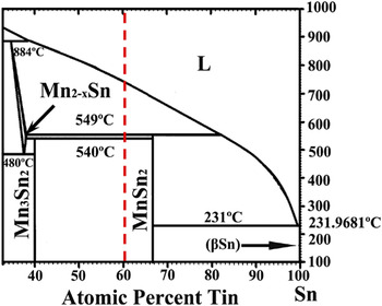
Figure 2 shows the equilibrium phase diagram of Sn–Mn binary alloy, and the concentration in the present work is shown as the dashed line. Under equilibrium solidification, Sn–40 at.% Mn alloy undergoes reactions as followsReference Liang, Du, Zhao, Liao, Tang, Zeng, Zhang and Xu20, Reference Stange, Fjellvåg, Furuseth and Hauback21:
(i) T L = 745 °C: L → Mn2−xSn
(ii) T P = 549 °C: L+ Mn2−xSn → MnSn2
The relevant part of Sn–Mn binary phase diagram [Reference Liang, Du, Zhao, Liao, Tang, Zeng, Zhang and Xu20].

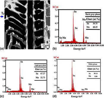
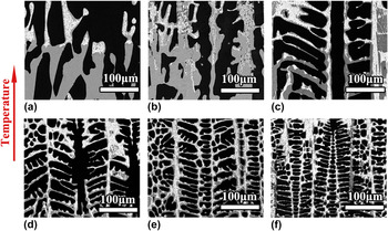
The Mn2−xSn phase changes into Mn3Sn2 phase when the temperature is below 540 °C. Backscattered electron microstructures of the directionally solidified Sn–40 at.% Mn peritectic alloy in the vicinity of peritectic reaction temperature T P at the growth rate of 10 μm/s is shown in Fig. 3. According to the EDX results of the solubility of components in each phase, the dark grey, bright grey, and white phases were identified as the primary Mn3Sn2 phase, peritectic MnSn2 phase, and (MnSn2 + Sn) eutectic phase, respectively. The solubility of Mn2−xSn, Mn3Sn2, and MnSn2 phases are very small. Figure 4 shows the morphological evolution of the peritectic interface in the directionally solidified Sn–40 at.% Mn peritectic alloy at different growth rates. It can be seen from Fig. 4 that with the increase of growth rate, developed secondary dendrites forms, and the migration of secondary dendrite arm can also be observed.
The chemical composition analysis of Sn–40 at.% Mn peritectic alloy by using SEM. EDX: (a) BSE image of the directionally solidified Sn–40 at.% Mn peritectic alloy at the peritectic interface (v = 10 μm/s, G = 40 K/mm); (b) the dark grey phase (A); (c) the bright grey phase (B); (d) the white phase (C).

Morphological evolution of the peritectic interface in the directionally solidified Sn–40 at.% Mn peritectic alloy: (a) v = 1 μm/s, (b) v = 5 μm/s, (c) v = 10 μm/s, (d) v = 30 μm/s, (e) v = 50 μm/s, (f) v = 100 μm/s.

B. Migration of secondary dendrite arm in Sn–Mn peritectic alloy
The migration of secondary dendrite arm has been observed in Al–Ni and Sn–Ni hyper-peritectic alloys. As shown in Figs. 4(b)–4(f), its novel feature is that the primary phase is not in contact with the peritectic phase during solidification, and solute atoms are transported through the liquid pool between adjacent secondary dendrite arms. Under equilibrium solidification, no liquid phase exists below T P in Sn–40 at.% Mn hypo-peritectic alloy, however, because the primary phase cannot be consumed completely during peritectic reaction, the liquid phase also exist at temperatures below T P and the migration of secondary dendrite arm can be observed.
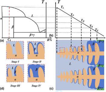
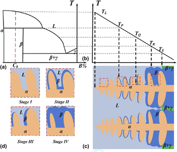
In the present analysis, as shown in Fig. 5, the migration of secondary dendrite arm can be divided into four stages. For a peritectic alloy with an initial composition of C 0 with the peritectic reaction L + α → β, the four stages are: stage I, from T L to T P; stage II, from T P to T Q; stage III, from T Q to T R; and stage IV, from T R to T E, where T L is the liquidus temperature, T P is the peritectic temperature, T Q is the temperature separating stage II and stage III, and T R is the temperature at which the interdendritic liquid is consumed completely.
Schematic illustration of the primary- and peritectic phase growth in peritectic solidification under a temperature gradient during dendritic solidification. (a) A typical phase diagram of a binary peritectic system, (b) temperature distribution across the solidification front, (c) schematic drawing of dendrite array, and (d) four enlarged illustrations showing the four stages, i.e., stage I–IV.

Figure 5(d) shows the enlarged illustrations of stages I–IV. In stage I, dendrites of primary phase precipitate from the melt. When peritectic reaction occurs, a peritectic layer forms and covers the dendrites of primary phase. Due to the coupling remelting/solidification at the hot/cold side of the liquid pool between two adjacent secondary dendrite arms, peritectic phase at the back edge of secondary dendrite arm of primary phase dissolves while peritectic phase at the front edge of secondary dendrite arm of primary phase solidifies. If the peritectic phase at the back edge of secondary dendrite arm of the primary phase disappears, then stage II is ended. In stage III, the back edge of secondary dendrite arm of primary phase continues to dissolve while the peritectic phase at the front edge of secondary dendrite arm of primary phase solidifies simultaneously. This is the experimental observation in the present work. In stage IV, the interdendritic liquid phase is consumed completely. In this stage, the diffusion through peritectic phase leads to further remelting of the primary phase and the solidification of peritectic phase.
In our previous work, the analytical solutions describing these stages have been proposed.Reference Liu, Li, Su, Peng, Guo and Fu11 However, these solutions are based on the assumption that the solubility of primary and peritectic phases are not nil. Therefore, it is not appropriate to apply these solutions directly in peritectic systems in which primary and peritectic phases are stoichiometric intermetallic compounds with nil solubility. The following assumptions are made to describe the four stages in peritectic systems in which the primary and peritectic phases are stoichiometric intermetallic compounds with nil solubility:
(i) Local equilibrium is established very rapidly at the solid/liquid interface.
(ii) Mn3Sn2/MnSn2 liquidus are assumed to be constant straight lines and the composition distribution in the liquid pool parallel to the temperature gradient follows the liquidus.
(iii) The temperature gradient (G) across the mushy zone is assumed to be constant, i.e., dT/dx = G.
(iv) As the diffusion coefficient in a liquid phase is greater than that in a solid phase by 3–4 orders of magnitude, solid-state diffusion is ignored.
(v) For the sake of simplification, the densities of phases involved are assumed to be the same.
(vi) The radii of secondary dendrite arms are assumed to be the same and the melting/solidification processes induced by the Gibbs–Thomson effect are ignored for simplification.
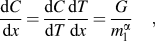
As shown in Fig. 5(d), two secondary dendrite arms and an interdendritic liquid layer are taken into consideration in stage I. The temperature gradient is upward. The temperatures of the hot/cold sides of the liquid pool are T 1/T 2 (T 1 > T 2). By referring to assumptions 1–3, a composition gradient is established across the interdendritic liquid layer, which can be given by
 $${{{\rm{d}}C} \over {{\rm{d}}x}} = {{{\rm{d}}C} \over {{\rm{d}}T}}{{{\rm{d}}T} \over {{\rm{d}}x}} = {G \over {m_{\rm{l}}^{\rm{\alpha }} }}\quad,$$
where  $m_{\rm{l}}^{\rm{\alpha }}$ is the liquidus slope of primary α phase.
With a concentration gradient established within the interdendritic liquid layer, solute atoms migrate from T 2 to T 1 through the liquid phase, leading to depletion of solute atoms at T 2 and enrichment of solute atoms at T 1. As a result, continuous remelting of the primary α phase into liquid at T 1 and solidification of the liquid phase into α at T 2 occur. By applying the Fick’s first law of diffusion and a mass balance for a small displacement  ${\rm{d}}r^{\rm{\alpha }}$ at the α/liquid interface:
 $$- D{{{\rm{d}}C} \over {{\rm{d}}x}} = {{{\rm{d}}r^{\rm{\alpha }} } \over {{\rm{d}}t}}\left( {C_{\rm{\alpha }} - C_{\rm{l}}^{{\rm{\alpha }},T_1 } } \right)\quad,$$
where  $C_{\rm{\alpha }}$ is the solute concentration of α phase at the α/liquid interface at T 1,
 $C_{\rm{l}}^{{\rm{\alpha }},T_1 }$ is the solute concentration of liquid phase at the α/liquid interface at T 1, D is the liquid diffusion coefficient, and t is the time. The remelting rate of secondary dendrite arm at T 1 can be given by
 $$v_{{\rm{remelt}}} = \left. {{{{\rm{d}}r} \over {{\rm{d}}t}}} \right|_{T_1 } = {{DG} \over {m_{\rm{l}}^{\rm{\alpha }} (C_{\rm{l}}^{{\rm{\alpha }},T_1 } - C_{\rm{\alpha }} )}}\quad.$$
Similarly, the solidification rate of liquid at T 2 can be given by
 $$v_{{\rm{solid}}} = \left. {{{{\rm{d}}r} \over {{\rm{d}}t}}} \right|_{T_2 } = - {{DG} \over {m_{\rm{l}}^{\rm{\alpha }} (C_{\rm{l}}^{{\rm{\alpha }},T_2 } - C_{\rm{\alpha }} )}}\quad.$$
From Eq. (3a),
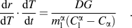 $${{{\rm{d}}r} \over {{\rm{d}}T}} \cdot {{{\rm{d}}T} \over {{\rm{d}}t}} = {{DG} \over {m_{\rm{l}}^{\rm{\alpha }} (C_{\rm{l}}^{\rm{\alpha }} - C_{\rm{\alpha }} )}}\quad.$$
In directional solidification, dT/dt = G·v, thus it can be obtained
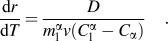 $${{{\rm{d}}r} \over {{\rm{d}}T}} = {D \over {m_{\rm{l}}^{\rm{\alpha }} v(C_{\rm{l}}^{\rm{\alpha }} - C_{\rm{\alpha }} )}}\quad.$$
In stage I,  $C_{\rm{l}}^{\rm{\alpha }} = C_{\rm{P}} + (T - T_{\rm{P}} )/m_{\rm{l}}^{\rm{\alpha }}$, thus the following relationship can be obtained:
 $${{{\rm{d}}r} \over {{\rm{d}}T}} = {D \over {v(C_{\rm{P}} m_{\rm{l}}^{\rm{\alpha }} + T - T_{\rm{P}} - m_{\rm{l}}^{\rm{\alpha }} C_{\rm{\alpha }} )}}\quad.$$
Similarly, in stage II
 $$v_{{\rm{remelt}}} = {{{\rm{d}}r} \over {{\rm{d}}t}} = {{DG} \over {m_{\rm{l}}^{\rm{\beta }} (C_{\rm{l}}^{{\rm{\beta }},T_1 } - C_{\rm{\beta }} )}}\quad,$$
 $$v_{{\rm{solid}}} = {{{\rm{d}}r} \over {{\rm{d}}t}} = - {{DG} \over {m_{\rm{l}}^{\rm{\beta }} (C_{\rm{l}}^{{\rm{\beta }},T_2 } - C_{\rm{\beta }} )}}\quad,$$
 $${{{\rm{d}}r} \over {{\rm{d}}T}} = {D \over {v(C_{\rm{P}} m_{\rm{l}}^{\rm{\beta }} + T - T_{\rm{P}} - m_{\rm{l}}^{\rm{\beta }} C_{\rm{\beta }} )}}\quad,$$
where T 3 and T 4 are the temperatures of the solid/melt interfaces where the peritectic phase remelts and solidifies, respectively.
In stage III,
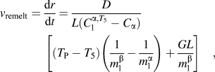 $$v_{{\rm{remelt}}} = {{{\rm{d}}r} \over {{\rm{d}}t}} = {D \over {L(C_{\rm{l}}^{{\rm{\alpha }},T_5 } - C_{\rm{\alpha }} )}}\left[ {\left( {T_{\rm{P}} - T_5 } \right)\left( {{1 \over {m_{\rm{l}}^{\rm{\beta }} }} - {1 \over {m_{\rm{l}}^{\rm{\alpha }} }}} \right) + {{GL} \over {m_{\rm{l}}^{\rm{\beta }} }}} \right]\quad,$$
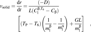 $$v_{{\rm{solid}}} = {{{\rm{d}}r} \over {{\rm{d}}t}} = {{( - D)} \over {L(C_{\rm{l}}^{{\rm{\beta }},T_6 } - C_{\rm{\beta }} )}}\left[ {(T_{\rm{P}} - T_6 )\left( {{1 \over {m_{\rm{l}}^{\rm{\beta }} }} - {1 \over {m_{\rm{l}}^{\rm{\alpha }} }}} \right) + {{GL} \over {m_{\rm{l}}^{\rm{\beta }} }}} \right]\quad,$$
 $$C_{\rm{l}}^{{\rm{\beta }},T_6 } - C_{\rm{l}}^{{\rm{\alpha }},T_5 } = (T_P - T_5 )\left( {{1 \over {m_{\rm{l}}^{\rm{\beta }} }} - {1 \over {m_{\rm{l}}^{\rm{\alpha }} }}} \right) + {{G \cdot L} \over {m_{\rm{l}}^{\rm{\alpha }} }}\quad.$$
Or equally,
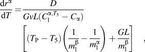 $${{{\rm{d}}r^{\rm{\alpha }} } \over {{\rm{d}}T}} = {D \over {GvL(C_{\rm{l}}^{{\rm{\alpha }},T_5 } - C_{\rm{\alpha }} )}}\left[ {\left( {T_{\rm{P}} - T_5 } \right)\left( {{1 \over {m_{\rm{l}}^{\rm{\beta }} }} - {1 \over {m_{\rm{l}}^{\rm{\alpha }} }}} \right) + {{GL} \over {m_{\rm{l}}^{\rm{\beta }} }}} \right]\quad,$$
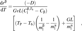 $${{{\rm{d}}r^{\rm{\beta }} } \over {{\rm{d}}T}} = {{( - D)} \over {GvL(C_{\rm{l}}^{{\rm{\beta }},T_6 } - C_{\rm{\beta }} )}}\left[ {(T_{\rm{P}} - T_6 )\left( {{1 \over {m_{\rm{l}}^{\rm{\beta }} }} - {1 \over {m_{\rm{l}}^{\rm{\alpha }} }}} \right) + {{GL} \over {m_{\rm{l}}^{\rm{\alpha }} }}} \right]\quad,$$
where T 5 and T 6 are the temperatures of the solid/melt interfaces where the primary phase remelts and the peritectic phase solidifies, respectively.
C. Effect of growth rate on migration of secondary dendrite arm
It can be observed from Fig. 4 that the migration of secondary dendrite arm is most significant at intermediate growth rates. This can be attributed to three reasons. First, the migration of secondary dendrite arm is associated with developed secondary dendrite morphology. If the growth rate is too low, as shown in Fig. 4(a), secondary dendrite branches cannot form, and the migration of secondary dendrite arm cannot be observed. Second, at very low growth rate, the solidification path of the Sn–Mn peritectic alloy is more close to the equilibrium condition, and little liquid left at temperatures below T P. Thus, the liquid pool that is necessary for transporting solute atoms does not exist. Third, when the growth rate is too high, the depression on the remelting/solidification process by continuous cooling is more significant and the migration of secondary dendrite arm is also restricted.
With regard to the third reason, as compared with the solidification due to continuous cooling, the remelting/solidification process by TGZM is dominant when vL/D < 1.Reference Liu, Li, Su, Peng, Guo and Fu11, Reference Allen and Hunt17 Where v is the growth rate, L is the width of the liquid pool, and D is the diffusion coefficient in the liquid. In the present work, the growth rate v is generally below 10−4 m/s and the width of the liquid pool L is of the order of 10−5–10−6 m. The diffusion coefficient in the liquid phase D is of the order of 10−9 m2/s. Then vL/D is of the order of 10−2, which is much <1. In this case, the remelting/solidification process by TGZM is dominant in our experiment, and the migration of secondary dendrite arm can be observed even at a growth rate of 100 μm/s [shown in Fig. 4(f)].
IV. CONCLUSIONS
In a Bridgman-type furnace, Sn–40 at.% Mn peritectic alloy has been directionally solidified at different growth rates (1–100 μm/s) under steep temperature gradient (40 K/mm), and the migration of secondary dendrite arm by TGZM has been investigated in this alloy.
(1) The migration of secondary dendrite arm that has been discovered recently in other peritectic alloys is observed during dendritic solidification of Sn–Mn peritectic alloys for the first time. Both the primary phase and the peritectic phase are intermetallic compounds with nil solubility in Sn–Mn peritectic alloy.
(2) Analytical solutions describing the migration of secondary dendrite arm in peritectic systems in which both the primary phase and the peritectic phase are intermetallic compounds with nil solubility have been proposed.
(3) The migration of secondary dendrite arm is most significant at intermediate growth rates when developed secondary dendrite arms form and the depression on TGZM by continuous cooling is not significant.
ACKNOWLEDGMENTS
This project was supported by the National Natural Science Foundation of China (Grant Nos. 51071062, 51271068, and 51274077), Open Project of State Key Laboratory of Mold and Die Technology of Huazhong University of Science and Technology (Grant No. 2011-P03). The Fundamental Research Funds for the Central Universities (Grant No. HIT. NSRIF. 2013002), and Project 973 (Grant No. 2011CB610406).