Introduction
The dual-reflector antenna is commonly recognized for its shorter focal length when compared to single reflectors. However, interference from the feed and sub-reflector can diminish the performance of such systems [Reference Kishk and Shafai1–Reference Moreira and Prata3]. The sub-reflector in this configuration must be sufficiently small to prevent disproportionate aperture blocking in axially symmetric reflectors [Reference Olver, Clarricoats, Kishk and Shafai2–Reference Kumar, Srinivasan, Lakshmeesha and Pal4]. Conversely, the main parabolic reflector diameter should be relatively large (typically exceeding 50 λ for classical reflectors). This presents a dilemma in design, as two contradictory conditions are imposed on the feed of dual-reflector systems. First, the radiation pattern should be as directive as possible to minimize spillover loss from the sub-reflector. Second, the feed dimension should be kept compact to minimize the blocking of rays from the sub-reflector to the main parabolic reflector. This necessitates a great feed aperture for the first condition and a small feed aperture for the second [Reference Kishk and Shafai1–Reference Moreira and Prata3].
Decreasing the main parabolic reflector diameter to 20 λ or less intensifies interactions between reflectors due to the negligible distance between the feed and the sub-reflector. This close proximity brings both reflectors into close alignment, making traditional analysis methods like physical optics (PO) and geometrical optics (GO) inadequate for achieving accurate results. Consequently, losses including illumination, spillover, and blockage are magnified, resulting in diminished antenna efficiency [Reference Olver, Clarricoats, Kishk and Shafai2–Reference Kim8].
To mitigate these challenges, previous research has proposed modifications to classic reflector antenna systems [Reference Olver, Clarricoats, Kishk and Shafai2–Reference Kim8]. For instance, in paper [Reference Olver, Clarricoats, Kishk and Shafai2], classic dual-reflector antennas are categorized into four configurations, with aperture efficiency improved through uniform-phase distribution at the primary focus of the feed antenna. In paper [Reference Franco5], a displaced axis dual-reflector antenna with a 4.6 m diameter main parabolic reflector and a gain of 33 dBic at 6 GHz is reported. Introducing a low-loss keeper for the displaced axis dual-reflector antenna is discussed in paper [Reference Tulum and Turk7], resulting in a 2-dBi gain improvement by altering the radiation beam path from the feed. Additionally, Kumar et al. [Reference Kumar, Ratnakar Deokule, Kumar, Sriharsha and Kumar9] investigate phase errors for displaced axis dual-reflector antennas, highlighting the achievement of minimum phase error and maximum gain with a ring phase center. The reflector antennas [Reference Liu, Du, Zhou and Xie10–Reference Zaman and Matin14], horn antennas [Reference Wang, Lin, Yang, Xu and Ge15–Reference Wu, Wang and Guo23], and other related antennas are discussed in papers [Reference Nasrabadi and Rezaei24–Reference Kumar and Praveen Kumar26], while antennas with circularly polarized radiation are listed in papers [Reference Arnaud, Chantalat, Monediere, Rodes and Thevenot27–Reference Haghparast, Rezaei and Zilouchian31].
In this study, we propose a modified structure to reduce losses and enhance efficiency. Initial analysis of antenna characteristics is conducted using GRASP software, based on GO and PO principles. The initial sizes of the main parabolic reflector and the sub-reflector are estimated, considering mechanical performance limitations. Subsequently, a feed horn antenna is designed to achieve the desired aperture distribution. A numerical method for small dual-reflector antennas is then employed to calculate the focal and phase center points. The complete dual-reflector antenna model is constructed using HFSS software, and coaxial line to SMA connectors are utilized for excitation. Additionally, two cylindrical metallic bars are employed in the cylindrical waveguide transition to enhance isolation between ports.
Analyses and design
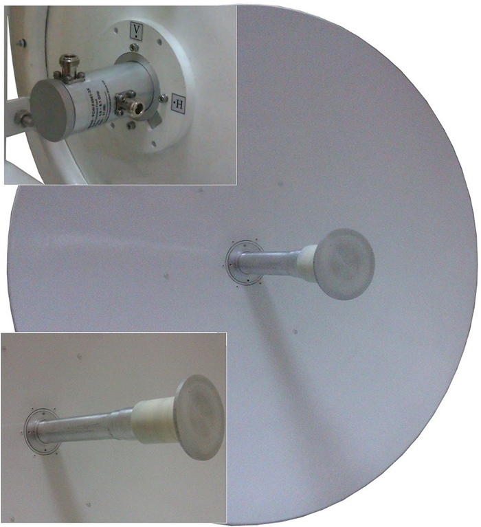
As is conventionally understood, traditional paraboloid reflectors are capable of transforming the spherical wave-front aperture from the feed into a planar wave-front surface dish. This conversion facilitates the generation of high gain and directive beams from the initial radiation pattern emitted by the feed. Compared to single reflector systems, dual-reflector antennas boast a shorter focal length and a lower profile. A photograph of the manufactured suggested antenna is shown in Fig. 1. To mitigate diffraction at the paraboloid aperture and reduce spillover, it is essential to ensure the initial beam is sharp. Typically, to achieve a low side lobe level, the ratio of the two reflectors in a classic dual reflector should be less than 0.1. Within the proposed bandwidth (BW) range, an F/D ratio of 0.37 with a main parabolic reflector diameter of 0.9 m proves to be a suitable choice. With this main parabolic reflector size, the primary optimization objective is to achieve a directivity of over 32 dB. Additionally, the side lobe level should be approximately −20 dB, and the |S11| parameter should be less than −15 dB within the operational band.
Photograph of the fabricated dual-reflector antenna structure.

Meanwhile, determining the position of the feed phase center is a critical aspect of the design process. Its electromagnetic problem is specified numerically by utilizing HFSS software. For the initial value of this location, the physical interaction of the feed with the main parabolic reflector is neglected. Another key consideration in designing this antenna is selecting the optimal feed for the structure. In the proposed waveguide, the TE11 radiation mode is the only mode propagating.
Horn antenna
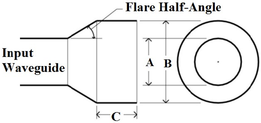
The dual-reflector scheme is equipped with a conical horn antenna covering the frequency range of 4–8 GHz. Designing the feed antenna for the dual-reflector system entails considering critical limitations such as edge-taper and half-subtended angle. For this purpose, a half-subtended angle of 15° and an edge-taper of 10 dB are determined. Accordingly, the aperture radius is fixed at 20 mm. Also, the horn length is established at 100 mm. Figure 2 illustrates a cut view of the conical horn antenna along with its sizes.
The cross-sectional view of the proposed conical waveguide of the proposed feed.

The feed is excited by a dual port coaxial line. Due to the symmetrical structure of the conical horn antenna, the proposed antenna exhibits insensitivity to polarization. It can support any linear polarity, whether vertically or horizontally linear polarization. Circular polarization is achieved by exciting two orthogonal ports with linear fields and the same magnitude simultaneously [Reference Gupta, Pandya, Sood and Jyoti18, Reference Zhang, Qi and Qiu19, Reference Arnaud, Chantalat, Monediere, Rodes and Thevenot27, Reference Haghparast, Rezaei and Zilouchian31]. Careful design of the diameter and length of coax pins is essential. The positioning of the first orthogonal ports plays a crucial role in achieving impedance matching.
Meanwhile, ensuring a high level of isolation between ports is essential. Low isolation between ports in the antenna system may lead to a remarkable increase in antenna temperature in the receiver sub-system or large power coupling into the other port when one port is used as the transmitter [Reference Kumar, Kumar, Kumar and Srinivasan6]. Therefore, achieving high isolation between ports is another significant challenge. Two cylindrical-shaped bars are added to the inside of the waveguide to enhance isolation between ports. These bars play a vital role in attaining the required isolation.
The propagation mode in section B can be determined by varying its diameter. In circular waveguides, the primary propagated mode is typically TE11. However, as the diameter increases, additional modes such as TM11 may also be propagated. In the dual-reflector system, increasing the diameter of the waveguide in section B leads to an increase in blockage losses. Additionally, in large-diameter horns, the possibility of high cross-polarization arises.
Therefore, only the TE11 mode should propagate in the circular waveguide at sections A and B. However, to achieve a directive beam from the feed, the diameter of section B should be slightly increased. In other words, the flare angle should be kept very low to prevent the excitation of the second mode in section B. The schematic of the feed conical horn is illustrated in Fig. 2.
Dielectric cylindrical-shaped keeper
The subsequent stage in antenna design involves the utilization of struts or keepers to support the sub-reflector. The primary objective of the design keeper is to eliminate the need for struts connected to the sub-reflector. The drawbacks associated with struts are well recognized. In symmetrical dual-reflector systems, struts can destroy the side lobe level and cross-polarization level of the secondary radiation patterns [Reference Kumar, Srinivasan, Lakshmeesha and Pal4]. In paper [Reference Kim8], the shaped keeper to improve gain in axially displaced ellipse (ADE) structure is considered with the best reflector illumination. But the mentioned designed keeper has a complicated structure to manufacture. Also, it should be carefully connected to a sub-reflector and then adjusted.
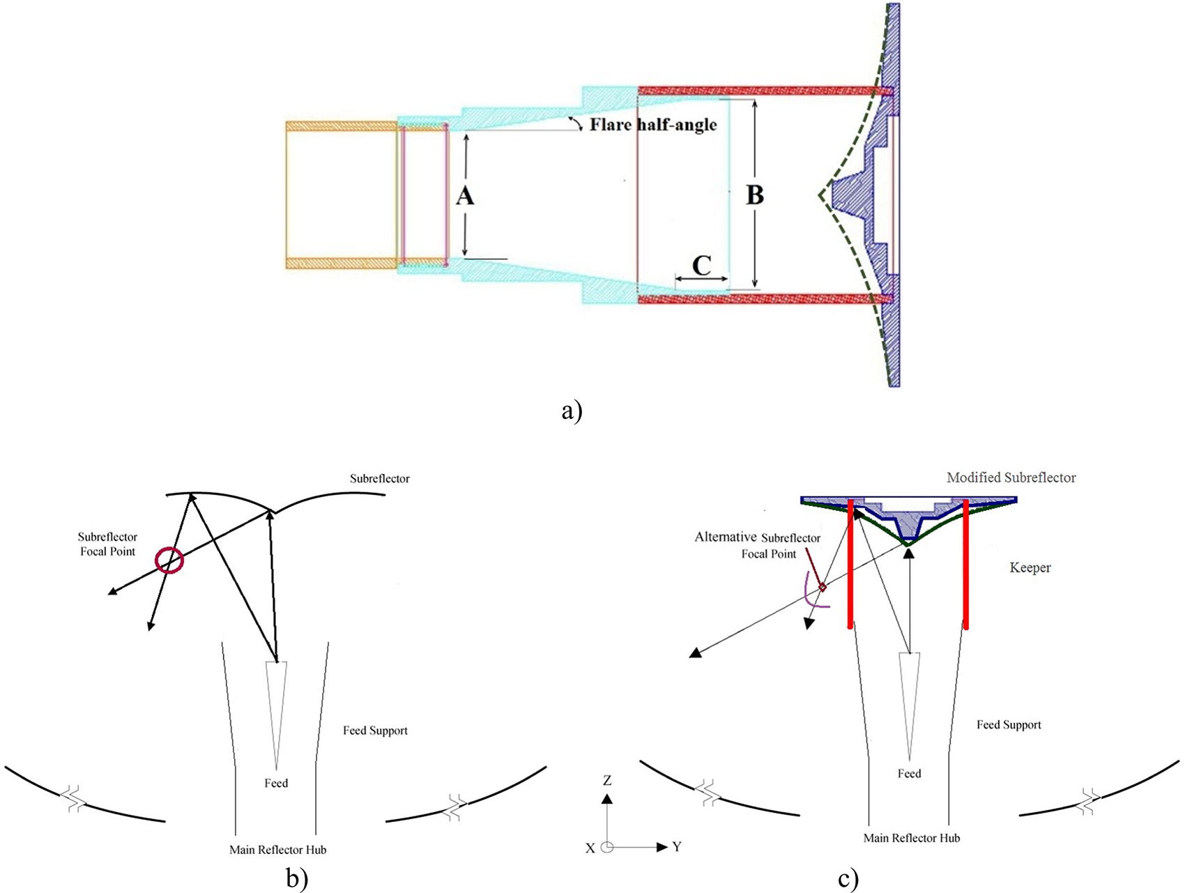
In this work, to enhance the performance of the ADE reflector antenna, a modified design is studied. A cheap dielectric cylindrical-shaped keeper with a simple structure was chosen. Then, the sub-reflector structure was readjusted with the initial dimensions of the ADE sub-reflector. The use of an appropriate dielectric material in the keeper can also aid in reducing cross-polarization levels [Reference Kishk and Shafai1]. The keeper has a thickness of 2 mm, and the dielectric permittivity of the pp copolymer material is ε r = 3.3, with a tan δ = 0.0004 at 5.5 GHz. Figure 3(a) illustrates a schematic view of the proposed horn and modified sub-reflector with the keeper. The cylindrical keeper is depicted by the red line. Figure 3(a) details are as follows: A = 40 mm, B = 63 mm, C = 13.6 mm, and flare half angle = 5°
(a) Feed and sub-reflector keeper specifications. Incident rays to be orthogonal to the sub-reflector focal point, (b) without cylindrical keeper, (c) with keeper.

.
Modified sub-reflector
Uniform distributions of amplitude and phase should be supplied to attain extreme gain by a reflector structure. Thus, phase error loss of the reflector should be minimized. In dual-reflector systems, the apex of the sub-reflector guides the radiation near the edge of the main dish. Thus, the center of the area of the main dish is illuminated by the minimum reflected power from sub dish edge. Thus, blockage loss from the feed horn will be diminished. In an ADE reflector, the sub-reflector has a caustic phase center where the loop caustic is situated over a circle [Reference Demirci, Sonmez, Tokan and Tokan12].
The comparative variation of the loop caustic location of the dual-reflector structure for classic ADE and the proposed structure are depicted in Fig. 3 (b) and (c). The schematics include a radial section and two incident rays are depicted at one half of the dual-reflector system. In Fig. 3 (c), two rays from the center and outer connected point of the keeper are reflected by it where the position of the rays is considered as incident rays to the outer and inner edge of the main reflector respectively. As a result, the illumination of the main reflector is more uniform than the ADE reflector with the classic keeper. Consequently, the high aperture efficiency (effective area to physical area ratio) from proposed structure is attained.
In other words, the sub-reflector is designed based on the ADE, depicted by a green dashed line. Subsequently, in the optimization process, a cylindrical keeper is introduced to enhance performance. Due to the interaction between the keepers and the sub-reflector, with the fixed shape of the keeper, partial sections of the initial ellipse-shaped sub-reflector are removed. By cutting the sub-reflector, the highly uniform illumination of the main reflector is achieved. The final sub-reflector configuration is achieved through optimization using HFSS software, as illustrated in Fig. 3. Lastly, the sub-reflector is constructed from aluminum, and its mechanical fabrication is carried out using CNC machining.
Measurement and discussion
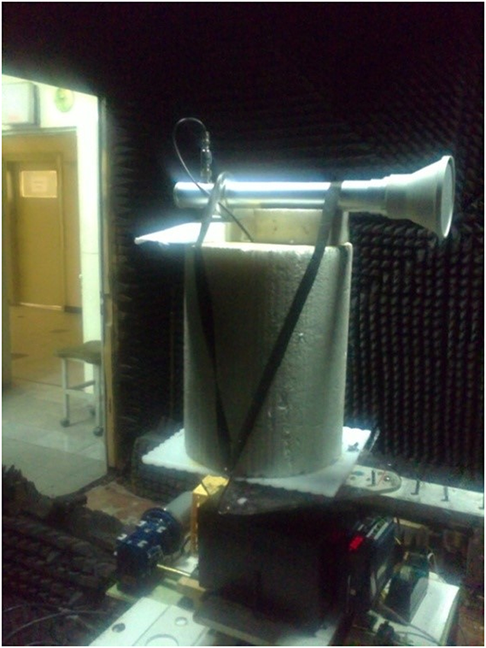
The photograph of the proposed antenna feed is depicted in Fig. 4. To assess the far-field radiation patterns, the fabricated antenna undergoes testing in an anechoic chamber. The horn antenna’s |S11| and isolation between ports are measured using the Keysight E8361C network analyzer.
The initial prototype of the horn antenna test setup at an anechoic chamber.

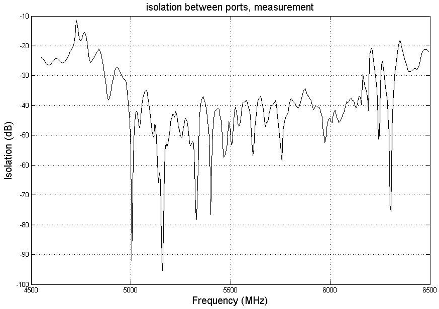
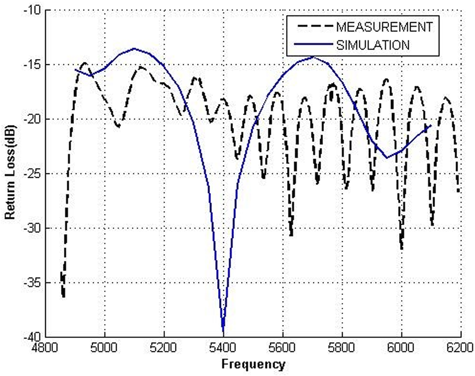
The results of the proposed dual-reflector antenna are depicted in Figs. 5–8. In Fig. 5, the isolation between ports is presented, demonstrating a value exceeding 38 dB. Figure 6 illustrates the comparison between the measurement and simulation of |S11|, showing a close agreement between the two. The impedance BW of the proposed dual-reflector antenna, characterized by |S11| < − 15 dB, is depicted before and after adding the reflector. Incorporating the main parabolic reflector enhances |S11| by approximately 1.5 dB, resulting in an impedance BW of about 25.4% (4.8–6.2 GHz).
The measured result of isolation between ports.

The results of |S11| of the suggested antenna.

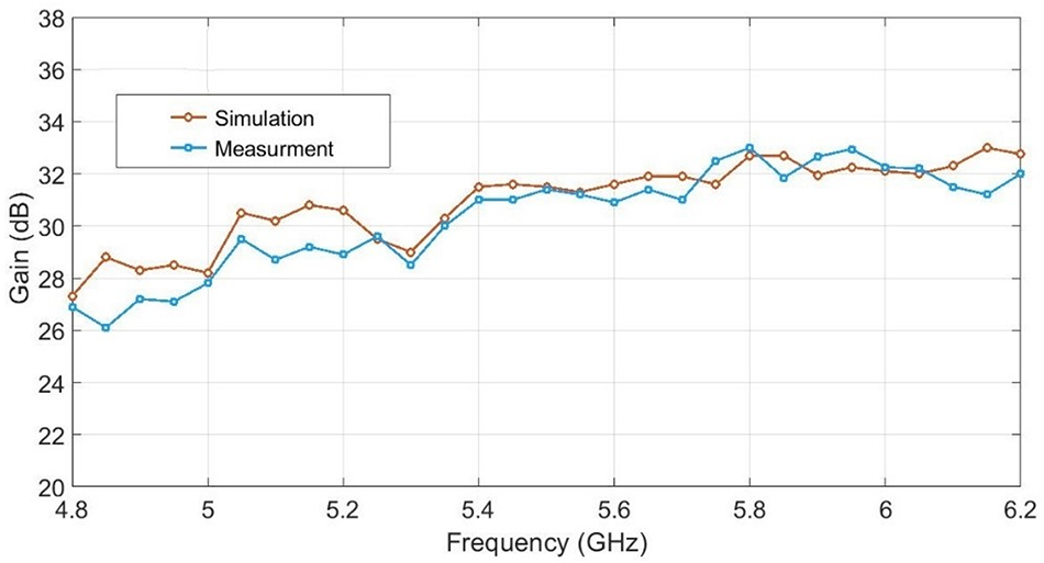
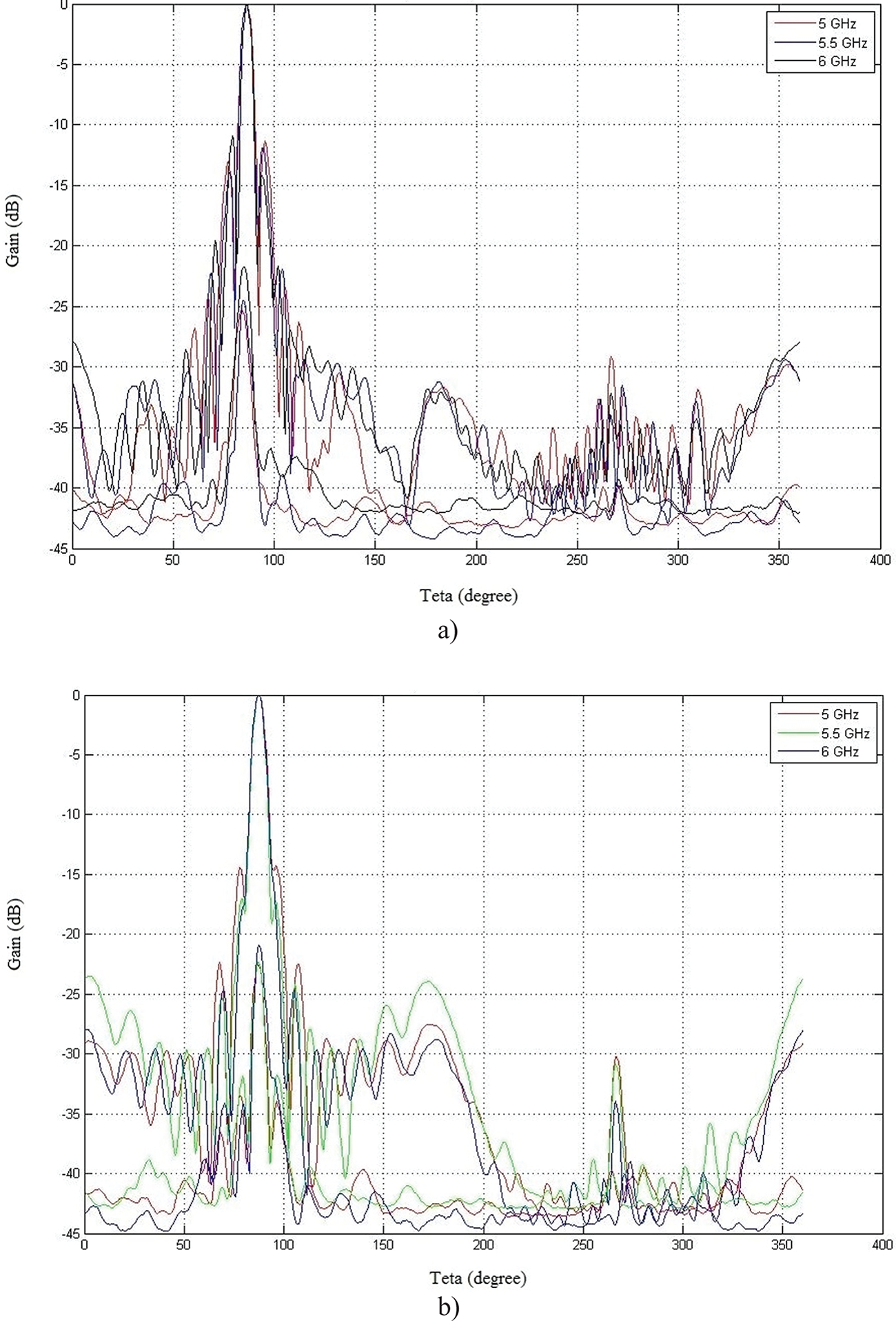
Figure 7 showcases the measured gain for the antenna design, ranging from 27.5 to 33 dB, indicating excellent performance for a small aperture antenna. Finally, the radiation pattern results in the orthogonal planes (φ = 0° and φ = 90°) are illustrated in Fig. 8, revealing a beam width of approximately 15° and a side lobe level of about 17 dB.
The maximum gain results of the suggested antenna.

The co- and cross-polar radiation patterns for three frequencies. (a) E-plane and (b) H-plane.

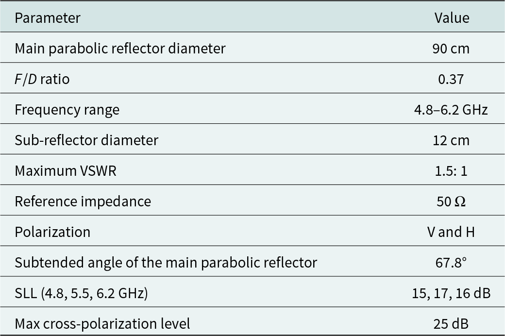
Despite generally suitable agreement between measured and simulated results, some discrepancies may arise due to construction errors. Further details of the presented dual-reflector antenna are summarized in Table 1.
The summarized property of the suggested antenna

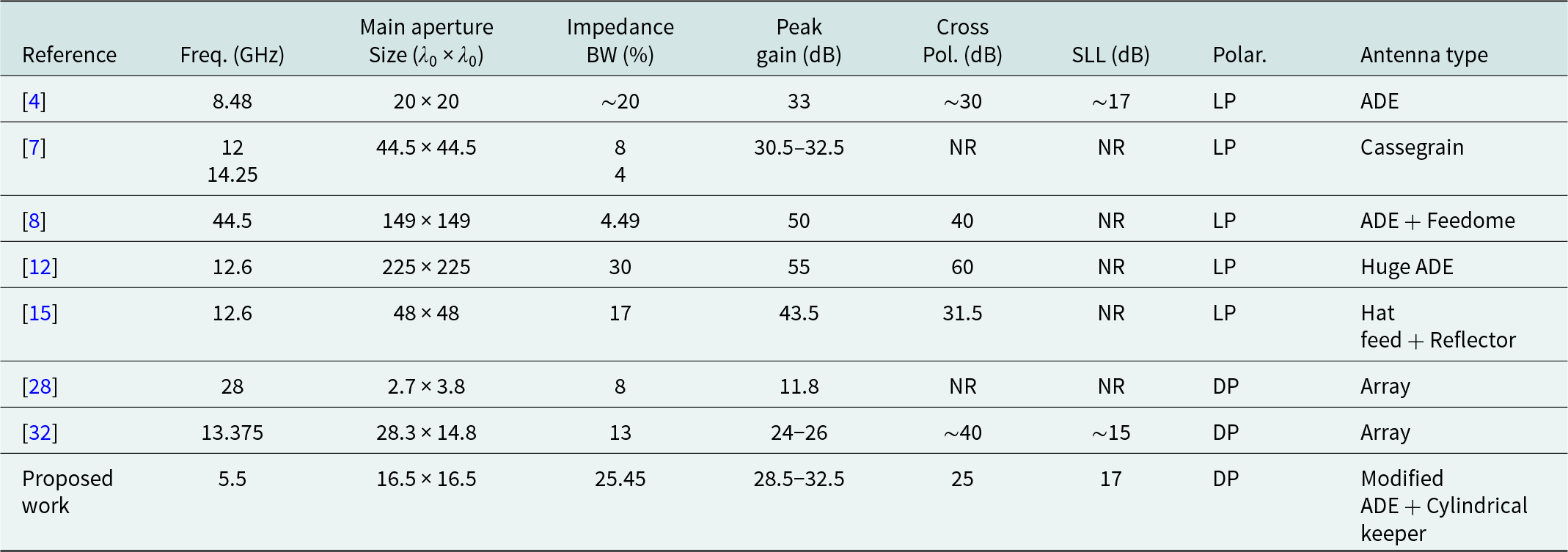
In Table 2, the comparison between the results and characteristics of the proposed antenna with some related work is presented. Based on the measurement results, the gain of proposed design at 5, 5.5, and 6 GHz is about 28.5, 31, and 32 dBi, respectively. This structure causes an efficiency better than 58%, which is a very good value for a small dual reflector at X-Band.
Comparison of the suggested reflector antenna and similar reported research

LP = linearly polarized, NR = not reported.
Clearly, the proposed antenna compared with other antennas where reported, has a wider impedance BW, cheaper fabrication, dual polarized (DP) and higher gain.
Conclusion
This work discusses the implementation of a dual-reflector antenna featuring dual linear polarization. A cylindrical keeper is employed to reduce blockage and illumination losses, while a modified sub-reflector based on a displaced axis dual-reflector antenna is designed. The measured results of the suggested structure indicate that the isolation between the two ports exceeds 38 dB within the frequency range of 4–6 GHz. The antenna achieves gains of 32 dBi, with an overall efficiency measured at 58%. The measured results validate the excellent performance and confirm the accuracy of the simulation results.
Data availability statement
Data sharing is not applicable to this paper as no new data were created or analyzed in this study.
Acknowledgments
This research is funded by Semnan University, research grant 1403942. Also, the authors would like to thank the Editor and reviewers for their constructive comments.
Competing interests
The authors declare no conflict of interest.

Amir Hossein Haghparast was born in Kashan, Iran, in 1985. He earned his bachelor’s degree in electrical and electronic engineering from the University of Kashan, Iran, in 2009. Subsequently, in 2012, he completed his master’s degree in wave communication engineering from K.N. Toosi University of Technology, Tehran, Iran. He completed his PhD degree in electrical engineering at Semnan University, Semnan, Iran, in 2024. Her research focuses on mobile and satellite communication antenna studies, encompassing various aspects such as MIMO mobile handset antenna designs, CPW, UWB, and reflector antennas for wireless and point-to-point applications, which he has been involved in since 2011. Additionally, his research interests extend to gap waveguide structures and millimeter-wave antennas. Email: a.h.haghparast@semnan.ac.ir

Pejman Rezaei was born in 1977 in Tehran, Iran. He earned his BSc degree in communication engineering from the Communication Faculty in Tehran, Iran, in 2000. Subsequently, he completed his MSc and PhD degrees at Tarbiat Modares University, Tehran, Iran, in 2002 and 2007, respectively. Currently, he is a professor at Semnan University, Semnan, Iran. His research interests encompass various areas within electromagnetics, including antennas, wave propagation, and biosensors. He actively contributes to advancing the understanding and application of electromagnetic theory in these fields. Corresponding author Email: prezaei@semnan.ac.ir

Ali Zilouchian earned his Ph.D. from The George Washington University in 1986. Presently, he serves as the Director of the Applied Engineering Research Center and Program Director at Keiser University Flagship Campus. Additionally, he holds the title of Emeritus Professor of Electrical and Computer Engineering at Florida Atlantic University (FAU) and serves as the Founding Project Director of a $4.5M project funded by the U.S. Department of Education (DOE). Throughout his distinguished career spanning academia and industry, Dr. Zilouchian has achieved numerous notable accomplishments, focusing on research and industry partnerships. He has secured over $9M in funding from prestigious organizations such as the U.S. DOE, the National Science Foundation (NSF), The Florida Board of Governors (BOG), Florida Power and Light (FPL), Motorola Inc., and the JPMorgan Chase Foundation, among others. For 13 years, Dr. Zilouchian held key administrative roles at FAU’s College of Engineering and Computer Science, serving as the Associate Dean of Academic Affairs and the Assistant Dean for Graduate Studies. He has published extensively, with one book and over 176 scholarly journal papers, book chapters, and refereed conference proceedings. Over the course of his career, he has supervised the completion of more than 21 PhD students. He has also served as an associate editor for two Engineering and Computer Science Journals and remains actively engaged in several professional societies and editorial boards. He holds senior membership status in IEEE, ASME, and ASEE societies, demonstrating his commitment to advancing the field of engineering and education. Email: zilouchi@fau.edu