Introduction
Frequency selective surfaces (FSSs) have been investigated extensively for two decades [Reference Munk1, Reference Raspopoulos and Stavrou2]. They have been widely used in various systems, such as antenna reflectors, radomes, spatial filters, electromagnetic band gap materials, as well as satellite communications [Reference Li, Zhang, Feng and Iskander3]. To increase the capabilities of multi-frequency antennas, the FSSs are correspondingly demanded to operate at multi-bands. In the past, many techniques have been studied to design FSS with a multi-band response. Single-layer and multi-layers FSSs have been respectively studied using genetic algorithm in [Reference Johnson and Rahmat-Samii4–Reference Wu7]. The fractal structure has self-similarity feature, which results in a multi-band property [Reference Romeu and Rahmat-Samii8]. Concentric rings with different sizes have been adopted in [Reference Wu and Lee9]. Complementary structures, patterned on different layers, were used to design dual- or tri-band FSSs [Reference Wang, Che, Chang, Chin and Chow10, Reference Huang, Wu and Lee11], which provide multiple transmission poles and zeros. A family of methodology techniques using non-resonant sub-wavelength periodic structures have been proposed to design FSSs [Reference Yan, Qu, Wang, Zhang, Zheng, Pang and Zhou12–Reference Yan, Wang, Qu, Ma, Feng, Pang, Zhang and Zheng16]. Such FSSs have the advantages of low-profile, multi-order, and dual-band performances. Based on the coupling matrix approach, a substrate integrated waveguide technique was proposed in [Reference Luo, Hong, Hao, Liu, Li, Chen, Zhou and Wu17, Reference Xu, Zhao, Zong and Wu18]. Such FSS exhibits good filtering performance though it has a narrow bandwidth and relatively high insertion loss.
Generally, large number of FSS structures mentioned above cannot be suitable for some special applications, especially in stealth area, such as a radome in a naval vessel. For a radome, the mechanical strength and weight are very important factors. Thus, the sandwiched type FSS has an important significance to enhance the mechanical strength and decrease the weight of the stealth radome [Reference Yan, Wang, Qu, Feng, Li, Chen, Zhang and Zheng19]. In [Reference Yan, Wang, Qu, Feng, Li, Chen, Zhang and Zheng19], a dual-band FSS with closed-space performance was proposed. The two bands cannot tune independently. However, in some practical applications, the three or more multi-band FSSs with a tuned-independent response will be very useful.
The objective of our work is to design a tri-band, band-pass FSS with highly-selective, broad band characteristics using a sandwiched structure. The proposed FSS includes two identical layers of periodic metallic arrays, which are separated by a foam layer. In each layer of the periodic array, the unit cell is composed of a gridded-triple square loop (G-TSL) structure. The FSS provides three pass-bands, in which a flat band response is presented. Three bands are separated by one or two transmission zeros, which leads to a sharp rejection on both sides of each pass-band. The simulation is implemented using full wave electromagnetic simulator CST Microwave Studio (MWS). The three bands are operating at C-, X-, and Ku-band, respectively. The central frequencies of the three pass-bands are 7.0, 10.9 and 14.0 GHz. Furthermore, each band can tune independently by adjusting the parameters of the corresponding square. To verify the simulated results, a prototype of the FSS is fabricated and measured. The simulated results agree well with the measured ones. In what follows the structure description, the operating principle, the simulated and measured results are presented and further discussed.
Design procedure and principles of operation
Figure 1(a) shows the equivalent circuit model (ECM) of the tri-band band-pass microwave filter. As we know, an inductor generates a pass-band while a serious LC circuit produces a transmission zero. Thus, the inductor L 1 may generate a pass-band around frequency f p1. Three serious circuits (L 1–C 1, L 2–C 2, and L 3–C 3) produce three transmission zeros at the frequencies f z1, f z2 and f z3 (f z1 < f z2 < f z3), respectively. Obviously, a transmission pole appears between two adjacent transmission zeros. The two transmission poles occur at frequencies of f p2 and f p3. The resonant frequencies of three transmission zeros of the topology of the tri-band band-pass filter can be express as
 $$f_{z1} = \displaystyle{1 \over {2\pi \sqrt {L_1C_1}}}, \;f_{z2} = \displaystyle{1 \over {2\pi \sqrt {L_2C_2}}}, \;f_{z3} = \displaystyle{1 \over {2\pi \sqrt {L_3C_3}}} $$
(a) ECM of the tri-band, and band-pass microwave filter, (b) ECM of the second-order, tri-band, and band-pass microwave filter utilized in this study.

Correspondingly, the resonant frequencies of three transmission pass-bands are calculated as
 $$\eqalign{& f_{\,p1} = \displaystyle{1 \over {2\pi}} \sqrt {\displaystyle{1 \over {C_2(L_1 + L_2)}}}, \;f_{\,p2} = \displaystyle{1 \over {2\pi}} \sqrt {\displaystyle{{C_2 + C_3} \over {C_2C_3(L_2 + L_3)}}}, \; \cr & f_{\,p3} = \displaystyle{1 \over {2\pi}} \sqrt {\displaystyle{{C_3 + C_4} \over {C_3C_4(L_3 + L_4)}}}}$$
where the couplings through high-order mode are ignored to simplify the analysis of our proposed FSS. Obviously, the topology shown in Fig. 1(a) is a tri-band band-pass filter with one transmission pole in each band. It is difficult to form a flat band response. Therefore, the two groups of filters shown in Fig. 1(a) should be parallelly connected through a piece of transmission line. The second-order band-pass microwave filter can be obtained, as shown in Fig. 1(b).
Note that, because of the lack of numerical investigation for the spatial couplings, the ECM provided is useful for qualitative analysis and for further understanding the operation mechanism. The next step is to map the equivalent circuit parameters in Fig. 1 to the physical dimensions of the FSS in Fig. 2. The formulas in [Reference Lee and Langley20, Reference Li and Shen21] can be used or further modified to obtain the initial estimate for the dimensions of G-TSL unit cells. The evaluations of the equivalent circuit parameters for the G-TSL array are given by:
 $$L_1 = {{X_1} / w} = {{F\lpar {D,w_1,\lambda} \rpar } / w}$$
 $$L_2 = {{2l_2 \times X_1 \times X_2} / {\lpar {w \times D \times \lpar {X_1 + X_2} \rpar } \rpar }}$$
 $$C_2 = {{2\varepsilon _{eff} \times B_2 \times l_2} / {\lpar {w \times D} \rpar }}$$
 $$L_3 = {{l_3 \times X_3} / {\lpar {w \times D} \rpar }}$$
 $$C_3 = {{2\varepsilon _{eff} \times l_3 \times B_2 \times B_3} / {\lpar {w \times D \times \lpar {B_2 + B_3} \rpar } \rpar }}$$
 $$L_4 = {{l_4 \times X_4} / {\lpar {w \times D} \rpar }}$$
 $$C_4 = {{2\varepsilon _{eff} \times l_4 \times B_3 \times B_4} / {\lpar {w \times D \times \lpar {B_3 + B_4} \rpar } \rpar }}$$
where X i = F(D, 2w i, λ), B i = 4F(D, g i, λ). The parameters w i and g i (i = 1, 2, 3, and 4) denote the width of the square loop and gap between two adjacent square loops, l i (i = 2, 3, and 4) represents the side length of each square loop. The factor F stands for the normalized inductance or capacitance of the strip grating has been defined in [Reference Yan, Wang, Qu, Feng, Li, Chen, Zhang and Zheng19].
 $$F\lpar {D,\;s,\;\lambda} \rpar = \displaystyle{D \over \lambda} \left( {\ln {\rm cosec}\displaystyle{{\pi s} \over {2D}} + G\lpar {D,\;s,\;\lambda} \rpar } \right)$$
where G is the correction term. It is obvious that equations (3)–(10) show clearly the relationships between the physical parameters and the equivalent circuit parameters. As a result, the initial guess for the dimensions of the proposed element can be obtained for a fixed operating frequency, though these formulas do not provide a very accurate approximation of the actual inductance and capacitance values. The couplings between two layers are not investigated numerically because of its complexity.
Structure of the proposed FSS (a) top view, and (b) side view.

FSS implementation
Since FSSs are essentially spatial microwave filters, the tri-band filter topology discussed in section ‘Design procedure and principles of operation’ can be used to synthesize a tri-band band-pass FSS. The filters presented in Figs 1(a) and 1(b) can be thought of as the ECMs of a tri-band FSS for a normally incident plane electromagnetic wave. Actually, the ECM of the proposed FSS is suitable not only for the normal incidence, but also for oblique incidence. Generally, a square loop and wire grid array can be regarded as a serious L–C circuit and an L inductor, respectively. The dielectric substrate supporting the structure is considered as a short transmission line with the length of d = h and wave impedance of Z = Z 0/ε r1/2. The free space at both sides of the FSS structure is modelled as a transmission line with characteristic impedance of Z 0 = 377 Ω. Thus, the FSS structure can be directly synthesized from Fig. 1. Figure 2 shows the top and side view of the synthesized FSS. The top layer structure is composed of a wire grid and three concentric square loops, as shown in Fig. 2(a). To decrease the weight of the FSS, the top and bottom layer are separated by a foam space. The second-order tri-band FSS is presented in Fig. 2(b). The relationship between circuit parameters shown in Fig. 1 and physical dimensions of the structure presented in Fig. 2, which depends on different polarizations and incident angles of the incoming wave, can also be obtained from equations in [Reference Li and Shen21]. For the sake of simplicity, the frequency response under normal incidence is usually synthesized. Practically, the normal incidence frequency response is of the most important because it can directly present the performance of the FSS.
Based on the analysis in section ‘Design procedure and principles of operation’, the initial estimate can be used as a starting point to fine tune the dimensions using in CST-MWS. For comparison, the frequency response of the ECM is implemented by ADS using the curve-fitting method. To save the space, the simulated frequency response from the ECM under normal incidence was plotted together with that of the FSS obtained by CST-MWS.
In Fig. 2(a), the dark gray areas represent copper with the electric conductivity of σ = 5.8 × 10⁷ S/m and the light gray areas denote the dielectric substrate which is the same as the dielectric layer shown in Fig. 2(b). The thin dielectric substrate is F4B-2 with a relative permittivity of 2.65 and a tangent loss of 0.001. The side length of the unit cell is D x = D y = D. The values of parameters labelled in Fig. 2 are listed in Table 1. Due to structural symmetry, the frequency response of the proposed FSS is insensitive to the polarization of incident wave under normal incidence.
Physical parameters and dimensions of the FSS (mm).

Simulation and experimental verification
Simulation
The frequency responses of the proposed FSS are implemented using full wave electromagnetic wave simulator CST-MWS. Firstly, the transmission and reflection coefficients of the single top layer structure presented in Fig. 2(a) under normal incidence are shown in Fig. 3(a). It is observed that there are three transmission windows centred at 6.7, 11.0 and 14.1 GHz, respectively. That is about f p1, f p2 and, f p3, as shown in section ‘Design procedure and principles of operation’. The −3 dB bandwidths of the three pass-bands are 3.0 GHz (4.8–7.8 GHz), 1.9 GHz (10.1–12.0 GHz), and 1.6 GHz (13.6–15.2 GHz). Correspondingly, the fractional bandwidths are 44.8, 17.3, and 11.3%, respectively. The three pass-bands have a broad band response. In addition, between two adjacent pass-bands, there are three transmission zeros positioned at about 9.0, 13.0, and 19.2 GHz, respectively. This is corresponding with the frequencies of f z1, f z2, and f z3 as described in section ‘Design procedure and principles of operation’.
Frequency response under normal incidence (a) the top layer structure, and (b) proposed FSS structure.

The transmission and reflection coefficients of the proposed FSS structure presented in Fig. 2(b) under normal incidence are shown in Fig. 3(b). Obviously, each pass-band has a flat band response. In each band, there are two transmission poles, namely, second-order response. This is because of the coupling of the top and bottom layer structures depicted in Fig. 2(b). The −3 dB bandwidths of the three pass-bands are 2.1 GHz (5.7–7.8 GHz), 1.4 GHz (10.2–11.6 GHz), and 1.0 GHz (13.5–14.5 GHz). In addition, there are two transmission zeros between two adjacent pass-bands, the one transmission zero leads to a fast fall off response near the upper side of the lower pass-band while the other one results in a sharp rejection near the lower side of the upper pass-band. In fact, in a high frequency range, there are other two transmission zeros leading to a wide out-of-band rejection in a higher frequency region. Thus, the predicted FSS has merits of high-selectivity characteristics.
The transmission coefficients under oblique incident angles for transverse-electric (TE) and transverse-magnetic (TM) polarizations are also simulated and shown in Fig. 4. It can be seen that the proposed FSS demonstrates a stable frequency response under oblique incident angles in a range of 0° and 45° for both polarizations. However, when an incident angle reaches up to 45°, the frequency response deteriorates for both polarizations. For TE polarization, insertion loss in the pass-band becomes larger while the out-of-band rejection changes further well. For TM polarization, a glob appears upper the third pass-band while the resonant frequency shifts to a lower frequency range. Fortunately, three pass-bands keep stable relatively. The structure's frequency response does not considerably change for incidence angles from 0° to 45° for both TE and TM polarizations. This can be attributed to the change of wave impedance [Reference Al-Joumayly and Behdad15], which in turn will change the loaded quality factor of the resonators of the coupled resonator FSS. For the TE incidence, as the angle of incidence changes, the wave impedance changes as Z 0/cos(θ), where Z 0 denotes the wave impedance of the free space. Therefore, for large incidence angles, the loaded quality factor of the parallel resonators increases or equivalently the bandwidth of each resonator decreases. The wave impedance for the TM polarization, however, varies as Z 0 × cos(θ). Therefore, for large-incidence angles, the loaded quality factor decreases for the TM mode resulting in the broadening of the FSS bandwidth.
Frequency responses under oblique incidence angles (a) TE mode, and (b) TM mode.

Experimental verification
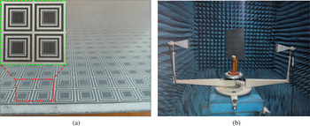
To further validate the simulated results, a prototype of the proposed FSS is fabricated using the printed circuit board technology and tested by utilizing a free space measurement method in a microwave anechoic chamber, as shown in Fig. 5. The metal layer structure is patterned on one side of a 0.6 mm thick F4B-2 substrate. The dielectric substrate is the same as that adopted in simulation. The two layers of the substrate are bonded onto both sides of a foam layer using very thin bonding films, and thus the proposed FSS can be obtained. The relative positions of metallic layers, dielectric substrates, and foam are shown in Fig. 2(b). The dimension of the prototype is 420 × 420 mm2, containing 35 × 35 elements. The overall electric thickness of the panel, including metallic layers, dielectric layers, bonding films, and foam, is about 6.2 mm which corresponds to the electric thickness of a quarter λ for the first band (λ is the free space wavelength at 6.7 GHz). In a microwave anechoic chamber, the FSS is placed on a rotated platform and three pairs of standard horn antennas operating in C-, X-, and Ku-bands, respectively, are placed at a distance of 1.2 m from each side of the FSS panel. It is to ensure that the FSS is excited with plane wave. To ensure the accuracy of the experiment, the measurement was taken by two steps: firstly, the transmission coefficient without the FSS prototype is measured; secondly, the FSS prototype is placed between the two antennas and the transmission coefficient is measured. Finally, the second tested results are calibrated using the results measured in the first step. Figure 6 shows the measured transmission performance of the FSS under normal incidence, and the simulated results are also given for comparison. Apparently, the measured frequency response agrees well with the simulated result, especially for the two lower pass-bands, though there is a little shift for the third pass-band. In simulation, the electromagnetic properties of the substrate (F4B-2) were assumed as non-dispersive. But, in measurement, the electromagnetic properties of the substrate (F4B-2) are dispersive, namely, the actual relative permittivity of the substrate in the Ku-band is smaller than the simulated one. The same phenomenon will appear in oblique incidence.
(a) Photograph of the fabricated FSS, and (b) measured system in a microwave chamber.

Comparison of the transmission response between measurement and simulation under normal incidence.

The transmission coefficients of the fabricated FSS under oblique incidence are also tested for both TE and TM polarizations, respectively. Figure 7(a) and 7(b) show the measured results for TE polarization with the incident angle of 30° and 45°, respectively. The corresponding simulated results are also shown for comparison. As is observed that the frequency response of the proposed structure is relatively stable to variations of the incidence angle even up to 45°, especially for two lower transmission windows.
Measured transmission under oblique incidence for TE polarization.

The transmission coefficients for TM polarization are also measured and presented in Fig. 8. It can be seen that all of the measured results agree well with the simulated ones, respectively, except that a little frequency shift for the third pass-band. It is mainly resulting from the tolerance of the relative permittivity between the simulation and measurement. In addition, it is different from the results of TE polarization. The grating lobe is appeared along the third pass-band and the transmission coefficients is greater as the incident angle increases. However, the measured results much better than the simulated ones. The transmission coefficients are less than −10 dB even when the incident angle reaches up to 45°. In summary, the measured results agree well with the simulated ones not only normal incidence but also oblique incidence. Also, it is concluded that the proposed tri-band FSS is feasible.
Measured transmission under oblique incidence for TM polarization.

Conclusion
In this paper, a sandwiched type FSS is designed and analyzed. The proposed FSS includes two identical layers of periodic metallic arrays, which are separated by a foam layer. The FSS provides three pass-bands, in which a flat band response is presented. Three bands are separated by one or two transmission zeros, which leads to a sharp rejection on both sides of each pass-band. The simulation is implemented using full wave electromagnetic simulator CST-MWS. To verify the simulated results, a prototype of the FSS is fabricated and measured. This type of FSS has important applications in stealth areas or satellite communication systems.
 Chun Yan Gao was born in Yan'an, Shaanxi, China, in 1980. She received a B.S. degree from Northwest University, Xi’an, China, in 2003, and an M.B. degree from the Xi Dian University, Xi’an, China, in 2010. Currently, she is an Associate Professor with Xi'an Youth Vocational College. Since January 2016, she is working toward her Ph.D. degree at the Xi’an University of Technology, China. Her current research interests include radar multi-formity of devices, antenna miniaturization, and frequency selective surface.
 Hongbin Pu (M’99) was born in Wei’nan, Shaanxi, China, in 1964. He received a B.S. degree from Northwestern University, Xi’an, China, in 1986, and a Ph.D. degree from the Xi'an University of Technology, Xi’an, China, in 2006. Currently, he is a Tenured Professor with Xi'an University of Technology. His current research interests include all aspects of power semiconductor devices, and RF devices on SiC and Si.
 Gao Shan was born in Shaanxi, China, in 1979. He received a B.E. degree from Xidian University, Shaanxi, China an M.B. degree from University of Electronic Science and Technology of China, Sichuan, China, respectively. Currently, he is working as an engineer at Xi'an Meteorological Bureau. His research interests are in atmosphere radar of a multielement.
 Chunlan Chen was born in Fujian, China, in 1981. She received a B.E. and an M.B. from Xi’an University of Technology, Shaanxi, China, in 2004 and 2007, respectively. From 2007 to 2011, she worked as a QE engineer in Shanghai SVA-NEC Liquid Crystal Display Co. Ltd. and as a QC engineer in Shanghai AVIC Optoelectronics Co., Ltd., respectively. From 2012 to 2015, she was engaged in teaching and research in semiconductor specialty. Currently, she is working toward her Ph.D. degree at the Xi’an University of Technology, China. Her research interests are in semiconductor materials and semiconductor devices.
 Yong Yang was born in Gansu, China, in 1988. He received the Doctor and Master degree from Xi’an University of Technology, Shaanxi, China, in 2015 and 2019, respectively. Currently, he is working as a teacher at Xi’an University of Technology. His research interests are in semiconductor material devices of wide band gap and 2D.