Introduction
Rasorber is the combination of the term radome and absorber. A radome exploits as a cover that is placed over the antenna to protect the radiating components from the harmful environment. To prevent major deterioration or malfunctioning, it shields the exposed elements of the antenna with a firm, which keeps refuse or frost away from the antenna. A frequency-selective radome is used from an electromagnetic (EM) perspective to prevent coupling with adjacent transmitting antennas that might interfere with the operation [Reference Kazakoff1]. To reduce the radar cross section (RCS), the radome is initially employed as a spatial filter for an incident EM wave [Reference Lynch2, Reference Richardson3]. A few articles [Reference Arseneaux, Akins and May4] and patents [Reference Costa and Monorchio5] on radome have become an initial platform to develop the FSR. The researchers have also designed invisible radome [Reference Li-Guo, Li, Meng, Wu, Mo, Fu and Yuan6], and resistive sheets (high impedance surface [HIS]) [Reference Dong, Cai, Yang, Wu, Cheng, Chen, Luo and Li7, Reference Zhang, Cheng, Luo and Chen8] to reduce the RCS in the early stages. Unfortunately, this frequency selective radome can only reduce the monostatic interrogations (ineffective for bistatic and passive radars) and causes high insertion loss by using the lossy material in the geometric design. Thus, to reduce the bistatic and passive RCS the absorbing material or circuit analog absorber is introduced in the design of the radome. This combination of the new structure is known as FSR. The researchers have evolved FSR to overcome the limitations of the radome and to address the communication blockade barrier of the frequency selective surface (FSS). The FSR transmits the in-band signals with minimal insertion loss while absorbing the out-of-band incident wave. Moreover, it ensures a significant reduction in bistatic and passive RCS in RADAR and stealth applications. According to paper [Reference Munk, Munk and Pryor9], the FSR is initially realized through the Salisbury screen which exploits a large unit cell and unstable filtering response in the oblique incidence. The microwave researchers later evolved various techniques to improve functionality and overcome the actual constraints of the FSR. Based on the relative positions, the existing FSR is categorized into three classes: FSR-AT for the absorption band below the transmission band [Reference Bakshi, Mitra and Ghosh10, Reference Sheng and Gao11], FSR-TA for the transmission band below the absorption band [Reference Yu, Kou, Ding and Zhang12–Reference Guo, Su, Li, Yang and Song17], and FSR-ATA for the transmission band between the absorption bands [Reference Sharma, Ghosh and Srivastava18, Reference Munk, Munk and Pryor19]. The absorbing layer typically consists of materials with high dielectric loss properties which effectively dissipate EM energy at non-resonant frequencies. The transmission layer is designed to have minimal impedance mismatch at resonant frequencies, thereby allowing high transmission at those frequencies. In the recent decade, the absorption and transmission bands were achieved separately where the transmission performance is resistant to the absorption band. However, these modes can accomplish a single absorption band (either lower or upper absorption band) which does notapply to RADAR and stealth applications. To further address this issue, the transmission within the absorption bands ATA mode is introduced which is suitable for stealth and RADAR applications. To obtain these aforementioned modes, the researchers have evolved various methods. Such technique includes 3D-based FSR [Reference Shen, Wang and Li20–Reference Wang, Wang, Shen and Wu23], active components [Reference Qian, Zhao, Ren, Chen, Jiang, Feng and Liu24–Reference Rathore and Ghosh28], single layer/distributed elements [Reference Ye, Wang, Xu, Zhang, Huangfu, Li and Ran29], interdigital resonators [Reference Chen, Sang, Guo and Fu30, Reference Hayat, Afzal, Lalbakhsh and Esselle31], parallel LC resonators [Reference Bakshi and Mitra32], magnetic materials [Reference Zhou, Yang, Qu, Wang, Wang, Ma and Xu33], multi-layer FSR [Reference Lalbakhsh, Alizadeh, Ghaderi, Golestanifar, Mohamadzade, Jamshidi, Mandal and Mohyuddin34], and lumped elements [Reference Wang, Qi, Shen and Wu35–Reference Chen, Yang, Bai and Fu37]. The frequency response of these techniques is obtained by using different ways:
1. Construct the transmission and absorption paths independently by using lossy and lossless resonators in a 3D unit cell where stable absorption bands are produced on both edges of the transmission bands without expanding the overall thickness of the FSR. Furthermore, it also retains a stable performance in oblique incidence.
2. To design a lossy layer on the top of the bandpass layer to achieve the minimum insertion loss.
3. To terminate the current flow on the lossy path in the unit cell. It is realized by incorporating the lumped resistors and lumped components [Reference Zhang, Jiang and Gong38] in the absorption layer.
Furthermore, the FSR is also designed in a single layer [Reference Yan, Kong, Wang, Xing, Xue, Xu, Jiang and Liu39] by using distributed elements where the design complexity is reduced in comparison with employing active and lumped elements in the structure. The limitation of the previous method is addressed by implementing the magnetic material or laminate absorbers [Reference Hamid, Shakhtour and Heberling40]. In the past, the qualitative research of the rasorber is explored and approximate analytical techniques (e.g., equivalent circuit) are implemented by microwave researchers. The novelty and the performance of the FSR are improved to conquer the limitations of the foregoing methods. In this review paper, the function of the FSR, and evaluation based on the structure, techniques, equivalent circuit model (ECM), and design are described.
Operating principle of FSR
The FSR is a periodic array of elements composed on the dielectric substrate. It is implemented to absorb the incident wave with low RCS in the stop band while penetrating it on the passband. It exhibits the performance of the FSR in a harmonious self-resonator network based on the floquet mode theory. The incident waves propagate electric currents to flow through the components of the periodic array, which enhances the level of coupling energy. The additional scattering fields are created by the generated electric currents. The resulting fields in the periodic layer of the FSR are produced by the interaction of the incident wave with the scattering wave. Therefore, the essential electric currents are produced by optimized resonators and also generate the required filtering response [Reference Anwar and Mao41]. The transmission wave is created as the electric current passes through the slots which act as a ground for the rasorber. This type of rasorber is highly recommended for RADAR and stealth applications. Since it can absorb the signals of hostile radars and communicate to the allied forces at the same time in a specific frequency range. Based on Munk’s perspective the working principle of the FSR is shown in Fig. 1.
Functionality of the FSR and (b) working principle of the FSR.

The FSR is classified into A-T-A and T-A/A-T modes. The schematic representations of each mode are illustrated in Fig. 2(a) for a better understanding of the FSR mechanism. In A-T mode (Fig. 2(b)), the absorbing material is placed on top of the transmission layer to absorb the unwanted frequencies while allowing the higher frequencies to pass through. The transmitting layer is followed by the absorbing layer as shown in Fig. 2(c). This configuration is designed when the initial transmission of certain frequencies is required but subsequent absorption is needed to prevent reflections or secondary emissions. In A-T-A mode, the absorption layer is placed before and after a transmission layer as represented in Fig. 2(d). At resonant frequencies, the transmitting layers allow the signal to pass through, but the second absorbing layer further reduces the overall transmission, ensuring that any frequencies not perfectly aligned with the resonant peak are absorbers. The first absorption (A) mitigates low- and high-frequency interference before the signal reaches the transmitting layer. The bandpass (T) layer facilitates the passage of specific resonant frequencies. The second absorption ensures that any signal that passes through the transmitting layer is further filtered, enhancing the selectivity and purity of the transmitted frequencies. The A-T-A-T-A (Fig. 2(e)) configuration is designed to provide a highly selective and controlled frequency response, ensuring that only specific frequencies are transmitted while others absorb at multiple stages. This configuration is particularly useful in applications requiring precise frequency selectivity and high-quality signal transmission, such as advanced communication systems, RADAR, and sensing technologies.
Ideal response for the FSR modes, (b) A-T, (c) T-A, (d) A-T-A, (e) A-T-A-T-A.

Equivalent circuit model of the FSR
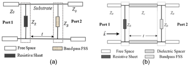
An ECM is used to examine the theoretical analysis of the rasorber (ECM). The basic ECM structure of FSR usually contains three parts: an upper resistive layer, air/single substrate in the centre, and a bandpass sheet at the lower. The FSR creates resistance (R) by comprising the lumped resistors/components, inductance (L), and the gaps between the resonators as capacitance (C). The required FSR is designed by the sequence of these elements. The ideal passband should have a minimum insertion loss (|S 11| = 0 & |S 21| = 1) and the incident wave should be completely absorbed in the optimal FSR (|S 11| = 0 & |S 21| = 0). To realize the functionality, the ECM of the resistive layer must be in the series point for the absorption band. Similar to the absorption layer, the ECM of the transmission layer needs to achieve parallel resonance at the same position [Reference Qiang, Zhou, Liu and Yao42]. To increase the performance of the FSR the lumped resistors [Reference Wang, Qi, Shen and Wu35–Reference Chen, Yang, Bai and Fu37] are incorporated into the design. By adding these lumped resistors, the absorption bands drop sharply due to the ohmic loss that is introduced as R in the ECM. Nevertheless, by using the distributed elements it is ignored. The LC components are added to avoid further disturbance from the absorption bands in the transmission layer. Therefore, the ECM changes simultaneously by introducing materials, and active or passive elements in the structure. The ECM for single and dual-layer FSR is represented in Fig. 3(a) and Fig. 3(b).
ECM for single-layer FSR and (b) ECM for dual-layer FSR.

The operating frequency for the distributed elements in the single or dual layer is given by,
 \begin{equation}f = \frac{1}{{2\pi \sqrt {LC} }}\end{equation}
The two-port networks for the air spacer and bandpass FSS based on the ABCD matrix are given [Reference Chen, Sang, Guo and Fu43],
 \begin{equation}
\left[ {\begin{array}{@{}ll@{}}
A&B \\
C&D
\end{array}} \right] = \left[ {\begin{array}{@{}ll@{}}
1&0 \\
{{Y_{{f_1}}}}& 1
\end{array}} \right]\left[\begin{array}{@{}ll@{}}
{\cos {\theta _{AT}}} & j{z_0}\sin {\theta _{AT}} \\
{j{Y_0}\sin {\theta _{AT}}}&\cos {\theta _{AT}}
\end{array} \right]\left[ {\begin{array}{@{}ll@{}}
1&0 \\
{{Y_{{f_2}}}}&1
\end{array}} \right]\end{equation}
where  ${Y_{{f_1}}}$ indicates top lossy sheet admittance, whereas
 ${Y_{{f_2}}}$ denotes the bottom lossy sheet admittance,
 $j\omega C$ represents the capacitance, and
 $j\omega L$indicates the inductance,
 ${R_1}$ indicates the front layer of the absorption band. The dual layer’s impedance parameters can be represented as follows:
 \begin{equation}{\text{ }}{z_{{f_1}}} = {R_1} + \frac{1}{{j\omega C + \frac{1}{{j\omega L}}}}\end{equation}
 \begin{equation}{z_{{f_2}}} = \frac{1}{{j\omega C + \frac{1}{{j\omega L}}}}.\end{equation}
The full-wave 3D EM solver CST Microwave Studio is used to simulate the FSR. The floquet mode theory is used to investigate the characteristics of the FSR, which adapts from the finite integration of the CST. The uniform plane wave excitation is used to study the reflection, transmission, and absorption properties of the proposed FSR. The EM wave is defined along the “x” and “y” directions. The x and y direction represents the unit cell where both Z min and Z max are set to open to free space.
Main applications of the FSR
Rasorber is pivotal in advancing modern engineering and technology solutions by optimizing performance across various applications. In communication systems, FSRs enhance spectral efficiency and mitigate interference in wireless networks like 5G and satellite systems, while improving antenna performance by reducing mutual coupling effects [Reference Jang, Jeon and Park44]. For RADAR and sensing technologies, FSRs enhance target detection and resolution in RADAR systems, reduce interference in automotive RADAR for better collision avoidance and autonomous driving, and improve sensor sensitivity and selectivity in applications like environmental monitoring. It also reduces the RCS for stealth technology, making vehicles less detectable, and manages electromagnetic interference (EMI) in electronic warfare to enhance communication and surveillance. For EMI shielding, FSRs protect consumer electronics and industrial equipment from EMI-induced malfunctions, ensuring compliance with EM compatibility standards [Reference Sahraneshin45]. In medicine and health care, FSRs enhance medical imaging modalities such as MRI and ultrasound by selectively filtering frequencies and optimizing signal transmission in wireless medical devices, crucial for remote monitoring and implantable devices. FSRs support IoT deployments in smart cities by managing EMI for robust communication networks and provide EMI shielding in building materials to enhance the performance and longevity of wireless systems [Reference Ghassemzadeh and Moinian46]. Continuous advancements in materials science, EM simulation, and manufacturing techniques are expanding the scope of FSR applications in emerging technologies, underscoring their critical role in contemporary engineering solutions.
Classification of FSR
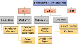
In this section, the FSR is categorized based on the structures and methods. The classification of the FSR based on the structures is described in Fig. 4.
Classification of the FSR.

2D structures
By cascading the resistive sheet and bandpass layer, a 2D FSR is constructed. This resistive layer is realized by incorporating the distributed elements and lumped components on the HIS. The principle of this 2D FSR includes that the bandpass FSS and resistive sheet must be approximately transparent at the passband with the least amount of insertion loss to allow for incident EM waves to pass through it. The transmission layer should almost totally reflect the absorption band, functioning as the ground plane for the top layer to absorb the incoming waves in a manner akin to a frequency selective absorber [Reference Chen, Sang, Guo and Fu43]. The majority of the existing literature is designed in 2D due to the reduced complexity. These 2D structures are developed in both single and dual layers with the incorporation of multiple resonators and elements. It is fabricated by using a printed circuit board and achieves less complexity compared to other dimensions. It also improves angular stability and leads to polarization-insensitive behavior effortlessly. However, due to large periodicity, the filtering response is unstable under the oblique incidence.
Single-layer FSR
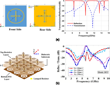
The single-layer rasorber is employed to enhance the novelty and interpretation of the FSR. The majority of the literature that is reported using this methodology was accomplished by utilizing distributed elements. By exploiting the closed resonators in a single structure mutual coupling takes place and produces a narrow bandwidth. Thus, this type of FSR is used for conformal, and flexible applications. The articles presented in the single-layer FSR are limited. A flexible FSS based on the rasorber exhibiting 2A-2T mode is proposed in paper [Reference Zargar, Rajput, Saurav and Koul47]. A dual-band transmission and absorption (2T-2A) of the FSR emerges from combining the design of a dual resonant absorber and dual bandpass FSS on the two sides of a single dielectric substrate. In addition to that, the front absorber design is optimized and attains a third resonant frequency (2T-3A). The single-layer FSR is constructed by implementing a cross and circular patch for absorption, etched cross slot, and corner loop for transmission as shown in Fig. 5(a), respectively. In paper [Reference Bakshi, Mitra and Teixeira48], a single-layer broadband absorber loaded with switchable components is proposed. This FSR is constructed by mounting an electric field pair resonator on a cross-dipole structure. The ON/OFF mode is enabled by utilizing the PIN diodes in a reconfigurable rasorber in an A-T-A position. A transmission band of 6.01 GHz with a minimum insertion loss of 0.38 dB is achieved by the configuration of the Jerusalem cross and cross slots (Fig. 5(b)). Similarly, the lumped resistors in a stripped patch in the lossy layer achieve a bandwidth of 2.95–5.65 GHz (62.79%) in the lower absorption and 7.4–9.25 GHz (22.12%) in the upper absorption. The complexity of the FSR design is reduced by exploiting the distributed elements. Nevertheless, compared to combining multiple layers and including passive components, the performance of the single-layer FSR has constraints.
Geometry and |S| parameter for (a) single-layer FSR composed with cross loop and cross slots and (b) stripped Jerusalem cross.

Dual-layer FSR
The dual-layer structure is introduced to obtain the wider absorption that overcomes the constraint of single-layer FSR. The isolated transmission and absorption layer is filled with an air gap to minimize the mutual coupling. The transmission and absorption structures are independent of each other. This FSR is developed by implementing the active and passive elements in the resonators. Thus, it will perform exceptional broader band absorption by incorporating the lumped resistors/components into the structures which are independent of the addition of layers. However, it ensures greater complexity in design and fabrication compared to the single-layer FSR.
FSR with passive elements
To obtain wider absorption, passive components such as lumped resistors and components are used in the design of the FSR These dual-layer FSR are highly recommended for stealth and RADAR applications since they obtain wider absorption with higher absorptivity. In paper [Reference Chen, Sang, Guo and Fu43], an FSR with a window that is fully transparent between absorption bands is shown. It is comprised of bandpass FSS and resistive sheets. The transparent window is achieved when the resistive sheets are parallel to the bandpass FSS regardless of the lossy properties. The parallel resonance is realized by using one finger of a strip interdigital resonator in the absorption layer and I-dipole in the transmission layer. This FSR achieves wideband in the 4.8–15.5 GHz range with a negligibly low insertion loss of 0.2 dB. Nevertheless, this FSR is complicated to realize the values of lumped resistors to achieve broadband. The new technique based on the ECM is proposed in paper [Reference Shang, Shen and Xiao49] with the implementation of the lumped elements. A wider bandwidth of 2.5–6.7 GHz for absorption and a narrow band of 4.4 GHz in the transmission is achieved using square loop and cross dipole arrays as depicted in Fig. 6(a). The metallic strips are sustained by a dual substrate with a thickness of 0.508 mm, that additionally can utilize the rasorber dual-polarization functionality and actualize the required circuit characteristics. The insertion of lumped resistors in the edge of the square loop and each strip of the cross dipole improves the bandwidth performance of the FSR. Furthermore, the lumped elements are utilized to evade the absorption shadow in the transmission layer. An FSR with dual-polarization is demonstrated in paper [Reference Chen, Han, Xiu and Che50] with an increased fractional bandwidth (FBW) of 96.5%. Two different resistors are comprised in the spiral slot array to enhance the absorption performance and attain the bandwidth of 3.4–4.1 GHz. The square ring slot is employed to achieve the impedance matching of the transmission layer. The resonators are composed of PEC material, and the gap between the layers is filled with air. The design of the frequency-dependent lossy structure with a square loop resonator provides the basis for the article reported in paper [Reference Huang and Shen51] Square Loop Hybrid Resonator (SLHR). Reducing current flow in the lossy path reduces the insertion loss. However, it is applicable for the A-T mode, and it is challenging for A-T-A to optimize the absorption while reducing the insertion loss. The hybrid resonator offers parallel resonance while bypassing the lossy path and improving insertion loss. By employing the absolute bare minimum of lumped resistors, this FSR achieves an FBW of 112% and an insertion loss of 0.29 dB (Fig. 6(b)). A cascaded lossy surface and transmission surface are amalgamated to form a two-layer structure that allows for broadband absorption with minimum insertion [Reference Luo, Yu, Yu, Jin, Fan and Zhu52].
Geometry and |S| parameters for (a) interdigital resonator with lumped resistors, (b) composition of square loop and cross dipole FSR, (c) spiral slot unit with resistors, and (d) hybrid resonator.

The FSR is constructed on a single substrate, depicted in Fig. 6(c), with a resistive square loop on top and a double square loop on the bottom. To reduce the undesirable transmission pole and achieve broadband in the frequency range of 3.83–10.8 GHz with an FBW of 95.3%, the dual stopbands are retained in a double square loop [Reference Wang, Liu, Kong, Yu, Zhang and Zhang53] offers a multifunctional hybrid FSR with a highly effective cross/co-polarized specular reflection band. The passband in the frequency range of 9.5–11.7 GHz is achieved using a transmissive cross-polarization conversion. The absorption band in the frequency range of 2.8–20 GHz (151%) is obtained by exploiting the arrow-shaped resonator incorporated with the lumped resistors as shown in Fig. 6(d). The microwave researchers have designed the FSR by comprising the passive elements to achieve a wider bandwidth for absorption and transmission. This approach requires a high level of difficulty to realize the precise impedance matching value and to solder the lumped resistors.
FSR with active elements
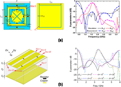
Active components are employed to increase the FSR’s operational flexibility. It is included in the bandpass or bandstop layer and modulates the bias-feeding network to alter the transmission characteristics. A switchable dual-polarized FSR based on a double-layered metallic structure array comprised of lumped elements and PIN diodes is presented in paper [Reference Qian, Zhao, Ren, Chen, Jiang, Feng and Liu54]. The FSR is composed of square slots in the top and bottom layer that are loaded with lumped resistors, PIN diodes, and metallic via which is represented in Fig. 7(a). By bypassing the PIN diodes, this FSR can rapidly switch between the rasorber and absorber modes (ON or OFF). The FSR exhibits a passband with an insertion loss of 1.7 dB at 1.6 GHz between two neighboring absorption bands in the rasorber mode. Likewise, if it changes to the absorber mode, it can operate between 0.8 and 3.4 GHz with an FBW of 124%. However, it obtains a lower insertion loss even by the incorporation of multiple elements. Based on the slot arrays, a switchable low-profile broadband FSR is suggested [Reference Han, Che, Xiu, Yang and Christopoulos26]. To construct the absorber, a combination of components like lumped capacitors, resistors, and diodes are used. Strip lines are used in both layers to achieve a wider frequency range of 1.7–5.5 GHz (109%) and a minimum insertion loss of 0.62 dB at 3.7 GHz. Under the technical requirements, the switchable components are employed to regulate the transmission window of the rasorber and it also works in rasorber or absorber mode. In paper [Reference Tang, Zhou, Liu, Yao and Liu55], a polarization-insensitive switchable FSR is presented with parallel-fed PIN diodes implemented. The lossy layer is employed to construct the fractal components with lumped resistors, which produce a wide range of 2.3–8.2 GHz (125.9%). The switched layer integrates a gridded square loop with a coaxial hybrid square ring to accomplish high-frequency transmission with a low insertion loss of 0.34 dB in the frequency range. This rasorber gives the best results by implementing a maximum no. of resistors and diodes in the structure. To avoid unwanted absorption performance in the transmission layer, a switchable FSR is developed in paper [Reference Bakshi, Mitra and Teixeira48] that comprises square slots and cross patches with the PIN diodes. This FSR is developed in a single dielectric substrate for A-T-A configuration without the air gap. This configuration is designed for airborne application and the multifunctionality of the design is realized by incorporating the PIN diodes as shown in Fig. 7(b). The ideal transmission is obtained by incorporating the lumped resistors with the active elements.
Geometry and |S| parameters of (a) hybrid square ring resonator and (b) stripped slots with PIN diode.

Multiple-layer FSR
Utilizing active and passive components will make the structure more complicated to realize an ohmic loss. To avoid those complications, the researchers have implemented multiple layers, stacking resonators, metasurface, and laminate absorbers in the FSR.
Laminate absorber
The Salisbury screen serves as the basis for the magnetic laminate absorber’s operation (destructive interface). It is positioned on the FSS layer with the ideal profile to exhibit transmissive and absorptive characteristics. However, the main constraint is a reduction of the insertion loss which leads to the slope steepness of the bandpass FSS. In paper [Reference Hamid, Karnbach, Shakhtour and Heberling56], a thin multi-layered structure with stacked FSS and a patterned laminate absorber is proposed. The stacking method is used to maintain the structure’s steep roll-off slope for absorption while reducing the thickness of the structure. The stacking of C-I-C layers, as illustrated in Fig. 8(a), allows for the bandpass FSS to function from 5 to 6 GHz in higher-order response. Similar to this, the patterned absorber is adhered to the other side of the FSS to achieve 8.26–12.0 GHz absorption.
Geometry and |S| parameters of (a) stacked FSS with laminate absorbers and (b) double lossy layer incorporated with lumped resistors.

Double lossy layer
To avoid the implementation of multiple layers, a double square loop lossy layers FSR was implemented in paper [Reference Xia, Wei, Liu, Zhang, Guo, Li, Bie and Jiang57] to achieve the required absorption and transmission characteristics. In addition to the multiple layers, the lumped resistors are used to realize the configuration as represented in Fig. 8(b). By stacking two lossy layers above a lossless layer, the FSR is constructed with two discrete absorption bands at frequencies of 2.5 GHz and 14.6 GHz. Low thickness is attained at 6.3 GHz to produce a low insertion loss of 0.78 dB. Even though the FSR is designed by using three layers, the thickness is reduced by sophisticated technology to avoid a significant compromise. Table 1 represents the comparison of 2D FSR with different layers.
Comparison of 2D FSR with different layers

2.5D structures
The 2.5D structures are used for the miniaturization and reconfigurable process. The limitations of 2D FSR such as large unit cells, multiple layers, and angular stability are overcome by using these structures. This 2.5D structure applies to both single and dual layers, although researchers have opted to employ it on dual layers to enhance the FSR’s functionality.
2.5D dual layers incorporated with lumped resistors and via holes
The convoluted resonators with the incorporation of the lumped resistors and the via holes are designed to achieve the FSR characteristics. In paper [Reference Yang, Jiang, Huang and Hong58], high transmission between the two absorption bands is suggested. In addition, to provide broad absorption bands in the frequency ranges of 3.67–6.80 GHz and 13.7–15.13 GHz, the T-shaped metallic strips introduce a significant equivalent impedance. The relative bandwidth (40.53%) of the transmission band is increased by utilizing the triple-layer bandpass FSS as shown in Fig. 9(a). By using this technique, it obtains a wider transmission band in the frequency range of 7.81–11.7 GHz. A broadband FSR with a 2.5D FSS structure is proposed in paper [Reference Yu, Costa and Monorchio59]. This FSR works in A-T-A mode by exploiting a lossy and lossless periodic surface separated by an air gap constitutes in Fig. 9(b). The absorptivity of 70% in the frequency range of 4.5–6.1 GHz and 8.3–10.9 GHz is achieved. It is obtained by inserting a strip-type parallel LC via structures with lumped resistors. The higher insertion loss of −3 dB (6.4–8 GHz) is acquired by two metal patches dispatched by a thin layer. Although it offers wide bandwidth, the θ performance is low. A novel 2.5D FSR called “knitted” structure (Fig. 9(c)) is employed in paper [Reference Yuan, Kong, Yu and Liu60] which is based on silicon vias to utilize the miniaturization. By the ECM, additional resonators are introduced in the array of metallic vias to achieve the wideband frequency response. This FSR is configured in the combination of a lossy cross frame and a lossless square loop. The insertion loss of 0.49 dB is obtained at 3.99 GHz by composing a knitted square loop. The FBW of 100% is obtained in the frequency range of 2.15–6.45 GHz by utilizing a knitted cross frame. It also realizes the oblique incidence up to 40° which is higher compared to the aforementioned rasorber. Even though these structures have more complications, they produce ideal absorption and transmission characteristics. Table 2 represents the comparison of 2.5D FSR.
Geometry and |S| parameters of (a) FSR incorporated with via holes, (b) T-shaped metallic resonator comprised of lumped resistors, and (c) knitted structure.

Comparison of 2.5D FSR

3D structures
The substrate-integrated waveguide technology is the basis of a 3D FSR. The novel 3D FSR exhibits consistent frequency response under oblique incidence and high selectivity bandpass FSS performance. Unlike the 2D and 2.5D FSR, multiple resonators are not required to develop the design. A 3D FSR comprised of parallel-plate waveguides in open-circuited and short-circuited 2D periodic arrays is proposed in paper [Reference Yu, Deng and Shen61] that works in A-T-A mode. This FSR is developed by ECM where the passband is obtained by a lossless open-circuited parallel waveguide with a lower insertion loss of 0.46 dB (1.57–2.36 GHz). Similarly, the absorption band is achieved by the short-circuited parallel-plate waveguide. The wider absorption bandwidth is obtained by adding a capacitor as an additional resonator (Fig. 10(a)). Furthermore, by adding the resonator the substrate thickness is reduced and increases the impedance matching. It achieves 80% absorptivity in the frequency range of 0.78–1.3 GHz (50%) and 2.72–4.06 GHz (39.5%).
Geometry and |S| parameters of (a) parallel-plate waveguide, (b) ferrite absorber, and (c) meander line polarizers.

Based on the magnetic materials a 3D wideband rasorber is introduced in paper [Reference Yu, Deng and Shen62]. The FSR is constituted of ferrite absorbers and a stepped impedance resonator (Fig. 10(b)). The ultra-wideband absorption is provided by the metal-backed SN-20 ferrite material which is capable of absorbing EM waves in the frequency range from 10 MHz to 1 GHz. The passband with a lower insertion loss of 0.45 dB is achieved by short-circuiting the ferrite absorber at 626 MHz. The previous articles improve the performance of the FSR by utilizing the lumped elements which are more complicated to design. To avoid those complications a lumped-free 3D FSR is proposed in paper [Reference Wang, Wang, Shen and Wu63] which works in A-T-A mode as shown in Fig. 10(c). This FSR is comprised of a stepped impedance resonator and magnetic absorber to obtain wideband characteristics. To minimize lumped components and obtain the low insertion loss of 0.83 dB at 7.1 GHz, a meander line resonator is positioned in the shunt connection The magnetic absorber is utilized to provide wider absorption in the frequency range of 3.22–12.11 GHz (121%). Owing to the characteristics achieved, the FSR works in single and dual polarization. Similarly, based on the ferrite absorber a 3D rasorber is proposed in paper [Reference Zhong, Feng, Zheng and Ma64]. The absorption and transmission bands are obtained by employing magnetic materials and an epsilon-near-zero waveguide. The lumped-free FSR obtains in the frequency range of 4.6–6.6 GHz with 35.7% of FBW. Table 3 represents the comparison of 3D FSR characteristics.
Comparison of 3D FSR

Future challenges and potential applications of FSR
FSR is extensively employed in various applications including RADAR systems, stealth technology, antenna radome, RADAR absorbing materials, and composite metamaterials. The FSRs are composed of broadband absorbers with the bandpass FSS. Despite the longstanding nature of this research area, it continues to be highly dynamic and rapidly advancing. The field encompasses a diverse array of applications and theoretical developments supported by a compressive suite of mature design and analysis tools. The FSR can be designed with both distributed and lumped components to achieve the desired characteristics. However, designing FSR with the lumped components, and diodes still increases the fabrication complexity, and realizing the precise values of the lumped components is challenging. As a result, the composition of distributed elements is still necessary to reduce the design complexity. However, the impedance matching with the utilization of the slots/stubs is not satisfactory compared to the FSR composed of the lumped elements, and dual-layer. Several critical challenges must be addressed in the successful design of the FSR structure. The choice of appropriate FSR resonators, unit cell dimensions, substrate, profile, and no. of layers are of major importance. Controlling these parameters to fit in demanding and compact applications is a challenging task and it generally requires critical and good EM behavior analysis of an FSR.
Current challenges:
1. Miniaturization:
• Miniaturization is essential for applications like antenna radome and military aircraft.
• Achieving the desired FSR characteristics in a single-layer unit cell is challenging due to the need for small electrical dimensions and high angular stability.
2. Broadband characteristics:
• Enhancing the operating bandwidth of single-layer FSR is critical for achieving miniaturization. Dual- and multiple-layer configurations still have unsatisfactory FBW.
• Techniques like fractal-shaped resonators and hybrid convoluted elements minimize unit cell dimensions and thickness. However, it doesn’t significantly improve the bandwidth performance.
3. Fabrication complexity using passive/active elements:
• Active elements (p-i-n diodes) and lumped resistors improve bandwidth and control absorption/transmission bands. However, incorporating too many elements leads to increased fabrication complexity and costs.
• Large biasing networks for active devices cause signal interference, and using active-HIS reduces elements but results in complex structures.
4. Higher optimization time:
• Designing dual, and multiple layers increases simulation time and optimization complexity. Single-layer FSRs in a back-to-back configuration also present challenge to find the optimized value for both absorption and transmission resonators at the same time.
• Researchers are currently exploring machine learning techniques to reduce optimization time, but identifying suitable algorithms and design methods is difficult.
5. Reduction of the mutual coupling:
• Designing separate absorption and transmission layers or a back-to-back configuration is necessary to minimize mutual coupling however complicates the design.
• Lower resonators in single-layer setups lead to impedance mismatches.
6. Methods of the FSR based on their applications:
The methods and their primary applications are briefly tabulated in Table 4 to facilitate a better understanding of suitable applications and their corresponding design techniques.
Trending methods and potential applications of the FSR

7. Future trends of FSR
Based on current trends and ongoing progressive research, significant advancements in the development of FSRs are anticipated in the coming years. Potential applications of FSRs in Table 5 include, but are not limited to:
Potential applications of the FSR

Overall, the versatility of FSRs and their ability to manage EM waves make them suitable for a wide range of emerging applications. As technology continues to advance, the use of FSRs is expected to grow, bringing new functionalities and improved performance to various industries.
Conclusion
This study dispenses a comprehensive review of the FSR based on 2D, 2.5D, and 3D structures. The techniques used to improve the novelty and performance by exploiting distributed elements, lumped elements/components, magnetic materials, metasurface, and multiple layers are discussed in detail. This paper provides basic information to study the evolution, techniques, ECM, and variations in the unit cell structure of the FSR. This analysis includes a contour of various ways to obtain the bandwidth, absorptivity, insertion loss, FBW, polarization independence, angular stability, and miniaturization of the FSR. These characteristics are compared and tabulated based on the relative positions of A-T/T-A, and A-T-A modes. The information will be helpful for microwave researchers to make further improvements in rasorber. This review article summarizes various solutions for reducing RCS in stealth, military, and RADAR applications.
Competing interests
There is no conflict of interest in the submission.

Geethanjali Govindarajan received her BE degree from Sri Sairam Institute of Technology, West Tambaram in the year 2020. She received her ME degree from Sri Sivasubramaniya Nadar College of Engineering in the year of 2022. She is currently pursuing her PhD degree at Anna University, Chennai. She is a research scholar in the Department of Electronics and Communication Engineering, College of Engineering Guindy (CEG) Campus, Anna University, Chennai. Her research interests are metamaterial absorbers, frequency selective rasorber (FSR) for RADAR and defense applications.

Gulam Nabi Alsath Mohammed received his BE, ME, and PhD degrees from Anna University Chennai in the years 2009, 2012, and 2015, respectively. He is currently serving as an Associate Professor in the Department of Electronics and Communication Engineering, Anna University, Chennai, India. His research interests include microwave components and circuits, antenna engineering, signal integrity analysis, and solutions to EMI problems. To his credit, he has 2 US patents and 18 Indian patents. He has published several research articles on antennas and microwave components in leading international journals. He has also presented and published his research papers in the proceedings of international and national conferences. He is currently serving as an Associate Editor in IET Microwaves Antennas and Propagation and Microwave and Optical Technology Letters.

Kirubaveni Savarimuthu obtained her BE and ME degrees from Anna University, Chennai. She currently serves as an Associate Professor in the Department of Electronics and Communication Engineering, Anna University, Chennai. She has 13 years of teaching and research experience. Her research interests include MEMS and NEMS device design and VLSI design. She is currently involved in the growth of ZnO nanorods for piezoelectric energy harvester and gas sensor applications. She is an active life member of IETE and a senior member of IEEE.

Malathi Kanagasabai completed her Bachelor of Engineering in Electronics and Communication Engineering and Master of Engineering in Microwave and Optical Engineering from Madurai Kamarajar University. She received her PhD on “Analysis of Rectangular Shielded Strip Line Enclosures” from Anna University, Chennai. She currently serves as a Professor in the Department of Electronics and Communication Engineering (ECE), Anna University, Chennai. Her research interests are antennas, UWB microwave components, electromagnetic shielding, and signal integrity analysis in RF-printed circuit boards. She has more than 25 granted patents including 2 US patents. She has authored more than 130+ research articles in leading international journals and guest edited a special section on THz components for Microwave and Optical Technology Letters.