Introduction
Owing to the growing demand for electrochemical energy storage (EES), high-performance electrode materials are needed to push electrochemical power sources beyond the barriers of current EES technologies.[Reference Bruce, Freunberger, Hardwick and Tarascon1] However, high-energy density rechargeable batteries should also be safe, environmentally friendly, and reliable through thousands of charge–discharge cycles to deliver capacities >1000 mAh/g and specific energy densities >600 Wh/kg in order to be practical for demanding applications such as high-endurance unmanned aerial vehicle systems (UAVs) and electric vehicles (EVs) capable of traveling over 500 km on a single charge.[Reference Bruce, Freunberger, Hardwick and Tarascon1–Reference Oleshko, Scordilis-Kelley, Xiao, Affinito, Talyossef, Elazari, Grinblat and Aurbach3] Light-weight rechargeable batteries based on the Li/S redox couple have the highest theoretical specific capacity of 1672 mAh/g of active material (S) among all solid elemental redox couples and a specific energy of 2567 Wh/kg, assuming complete reaction[Reference Bruce, Freunberger, Hardwick and Tarascon1–Reference Ji, Lee and Nazar4]:
 $$16{\rm L}{{\rm i}^ {\circ}} + {\rm} S_8^ {\circ} \to 8{\rm L}{{\rm i}_2}{\rm S}.$$
In practice, capacities typically range from 800 to 1200 mAh/g, which is four to five times that of current Li-ion technology.[Reference Bruce, Freunberger, Hardwick and Tarascon1, 2] Moreover, the low cost and abundance of sulfur make Li–S batteries an attractive alternative to Li-ion batteries.[Reference Bruce, Freunberger, Hardwick and Tarascon1, Reference Ji, Lee and Nazar4] As a practical proof of concept, the UAV Zephyr-7 (QinetiQ, UK) (Certain equipment, instruments or materials are identified in this paper in order to adequately specify the experimental details. Such identification does not imply recommendation by the National Institute of Standards and Technology nor does it imply the materials are necessarily the best available for the purpose.) has established an official world endurance record for its flight from 9 July to 23 July 2010 (over 2 weeks) lasting 336 h and 22 min, being powered and charged with Si solar arrays (Unisolar) during the day and then Li–S batteries (350 Wh/kg, Sion Power) by night.[2] Low-temperature performance down to T = −70 °C with non-aqueous liquid electrolytes could particularly enable the use of light weight Li–S batteries for long-distance high-altitude UAV/pseudo satellite stratosphere flights.
Although the intrinsic specific capacity of S8 far exceeds that of current Li-ion systems, Li–S batteries have not achieved widespread commercialization due to limited lifetime from either gradual capacity fading or outright failure. Initial capacities of 1200 mAh/g are fairly common, but retaining this capacity out to several hundred cycles remains challenging. This poor long-term performance has been associated with the “shuttling” of linear polysulfides dissolved into the electrolyte medium. A second cause of the limited cycle stability in Li–S batteries arises from the deposition of solid Li2S discharge products on the cathode.[Reference Oleshko, Scordilis-Kelley, Xiao, Affinito, Talyossef, Elazari, Grinblat and Aurbach3] As the discharge proceeds, soluble high-order polysulfides are reduced to Li2S2 and Li2S discharge products, which are insoluble in non-aqueous ethereal solvents typically used in electrolytes and deposit as hard, intractable solids on the cathode surface. Further complications arise during cycling as sulfur undergoes a volume expansion of roughly 80% when forming Li2S generates mechanical stress on the cathode framework. Repeated cycling creates cracks in the cathode which, over time, ultimately lead to Li2S encrusted carbon detaching from the electrode. Once electrically disconnected, the Li2S is no longer accessible for recharging, resulting in a loss of capacity. Suppressing the cathode damage caused by the Li2S deposition is essential for extending the long-term performance of Li–S batteries.
Since the seminal publication by Nazar and co-workers,[Reference Ji, Lee and Nazar4] a number of reports have demonstrated the preparation of sulfur-based nanocomposite cathodes. These strategies typically encapsulate or sequester the S8 and its electrochemically generated polysulfides into blends that are intimately mixed with conductive carbon nanoparticles, graphene, or core–shell colloids, to create enhanced cathodes for Li–S batteries.[Reference Li, Cao, Qi, Saraf, Xiao, Nie, Mietek, Zhang, Schwenzer and Liu5–Reference Scordilis-Kelley, Mikhaylik, Kovalev, Oleshko, Campbell and Affinito18] Cui and co-workers[Reference Seh, Li, Cha, Zheng, Yang, McDowell, Hsu and Cui19] demonstrated that yolk–shell S8–TiO2 colloids exhibit high capacity retention and extended lifetimes achieving roughly 700 mAh/g at 1000 cycles at a C/2 rate. They have also demonstrated a simplified one-pot dispersion polymerization method to prepare these type of core–shell colloids, also capable of retaining significant capacity out to 1000 cycles.[Reference Li, Zheng, Yang, Seh, Liu and Cui20] Alternatively, the use of sulfide polymers [e.g., 2,5-dimercapto-1,3,4-thiadiazole (DMAcT)][Reference Liu, Visco and Dejonghe21–Reference Chao, Lan and Yu23] and of vulcanized polyaniline nanotubes[Reference Xiao, Cao, Xiao, Schwenzer, Engelhard, Saraf, Nie, Exarhos and Liu24] have been investigated as a route for electroactive cathode materials. More recently, processing or carbonization with Li2S salts has been explored to create bulk electroactive materials for advanced Li–S cathodes.[Reference Yang, McDowell, Jackson, Cha, Hong and Cui15, Reference Yang, Zheng, Misra, Nelson, Toney and Cui25, Reference Yao, Zheng, Hsu, Kong, Cha, Li, Seh, McDowell, Yan, Liang, Narasihman and Cui26] Cycle lives of over 1000 charge–discharge cycles at a capacity of 1470 mA/hg for cells comprising pre-lithiated Si–carbon and all-carbon (non-Li) anodes coupled with sulfur-infused porous hollow sphere cathodes have been demonstrated.[Reference Brückner, Thieme, Böttger-Hiller, Bauer, Grossmann, Strubel, Althues, Spange and Kaskel27] Recent advances in the utilization of all solid-state Li–S batteries have been reported to obviate the issues associated with liquid electrolytes.[Reference Hayashi, Ohtomo, Mizuno, Tadanaga and Tatsumisago28–Reference Hassoun, Kim, Lee, Jung, Lee, Sun and Scrosati32] All of these systems represent significant advances in the creation of novel electroactive materials to improve the electrochemical performance of cathodes in Li–S batteries. However, challenges still persist in the creation of chemistries and materials that are inexpensive and amenable to large-scale production, while retaining high charge capacity and electrochemical stability.
To meet these challenges, we have developed a new chemical methodology, termed inverse vulcanization, to prepare electroactive organosulfur polymers as alternative cathode materials for Li–S batteries. These sulfur polymer cathodes exhibit an initial specific discharge capacity of 1225 mAh/g, and retain high reversible specific discharge capacity and cycle stability (1005 mAh/g at 100 cycles at rate = C/10).[Reference Chung, Griebel, Kim, Yoon, Simmonds, Ji, Dirlam, Glass, Wie, Nguyen, Guralnick, Park, Somogyi, Theato, Mackay, Sung, Char and Pyun33–Reference Griebel, Li, Glass, Char and Pyun35] The poly[sulfur-random-(1,3-diisopropenylbenzene)] [poly(S-r-DIB)] copolymers are part of an emerging class of electroactive polymers that can be utilized as electrode materials for high-energy density Li–S batteries such as conjugated conductive polymers, sulfide polymers, and nitrosyl radical polymers.[Reference Liu, Visco and Dejonghe21–Reference Chao, Lan and Yu23, Reference Tatsuma, Sotomura, Sato, Buttry and Oyama36–Reference Griebel, Namnabat, Kim, Himmbelhuber, Moronta, Chung, Simmonds, Ngyugen, Mackay, Char, Glass, Norwood and Pyun38] We previously examined the electrochemical properties of a poly(S-r-DIB) copolymer with 10% by mass of DIB and demonstrated that they can be directly used as cathode materials in Li–S batteries, exhibiting high specific capacity and cycle stability (823 mAh/g at 100 cycles).[Reference Chung, Griebel, Kim, Yoon, Simmonds, Ji, Dirlam, Glass, Wie, Nguyen, Guralnick, Park, Somogyi, Theato, Mackay, Sung, Char and Pyun33] However, the mechanism and underlying structure–property correlations for these materials have yet to be identified.
In this report, we explore the structural origins for this increased capacity retention by characterizing the multi-scale morphology of composite poly(S-r-DIB) copolymer-based cathodes with varying DIB content (0%, 10%, and 50% by mass) in relation to the electrochemical performance. We employ a suite of analytical electron microscopy techniques, that includes phase-contrast high-resolution transmission electron microscopy (HRTEM), conventional transmission electron microscopy, scanning TEM (STEM), selected-area electron diffraction (SAED), correlative energy-dispersive x-ray spectroscopy (EDXS), electron energy-loss spectroscopy (EELS), and field-emission scanning electron microscopy (FESEM), to study the hierarchical morphology of both pristine and cycled cathodes. Through correlations between the cathode structure, composition, electrical conductivity, and electrochemical performance, this work sheds insights into the mechanisms of the enhanced capacity retention for these new composite cathode materials for the prospective high-energy density Li–S battery systems.
Experimental section
The poly(S-r-DIB) copolymer materials used in this study were synthesized by inverse vulcanization through direct dissolution and copolymerization of DIB in liquid sulfur.[Reference Chung, Griebel, Kim, Yoon, Simmonds, Ji, Dirlam, Glass, Wie, Nguyen, Guralnick, Park, Somogyi, Theato, Mackay, Sung, Char and Pyun33] This process is a bulk copolymerization of molten sulfur and DIB heated above the floor temperature (T f = 159 °C) for the free radical ring-opening polymerization of S8. While sulfur is classically known to form living polymers at temperatures above T f, these macromolecules depolymerize upon cooling back to room temperature. The copolymerization of S8 with varying DIB ratios from 5% to 50% by mass has been shown to form high-molecular mass sulfur-based copolymers that are not only stable at room temperature, but also retain the critical electroactive S–S bonds that are needed for battery function.[Reference Chung, Griebel, Kim, Yoon, Simmonds, Ji, Dirlam, Glass, Wie, Nguyen, Guralnick, Park, Somogyi, Theato, Mackay, Sung, Char and Pyun33, Reference Simmonds, Griebel, Park, Kim, Chung, Oleshko, Kim, Kim, Glass, Soles, Sung, Char and Pyun34]
Cathodes were fabricated by blade coating a ball-milled slurry, consisting of either elemental sulfur or the active poly(S-r-DIB) copolymers, mixed with the conductive carbon nanoparticles (Timcal Super C65) and a polyethylene binder onto an aluminum current collector. The mass ratio of the components (sulfur-containing material: carbon : binder) in the slurry was held constant at approximately 75:20:5, respectively. The composite cathodes for a standard 2032 coin cell were prepared with a Li metal foil anode and cycled at rate of C/10, according to procedures described previously in detail.[Reference Simmonds, Griebel, Park, Kim, Chung, Oleshko, Kim, Kim, Glass, Soles, Sung, Char and Pyun34]
The morphology, microstructures, and elemental compositions of pristine and cycled composites of the poly(S-r-DIB) copolymer–carbon cathodes were analyzed using a cold field-emission gun Hitachi S4700 scanning electron microscope (FESEM) equipped with an Oxford high-speed 80 mm2T max silicon-drift EDX detector. For FESEM, the cathode film samples were mounted on aluminum alloy stabs. Medium- and high-resolution scanning and transmission electron microcopy (S/TEM) imaging, SAED, EELS, and EDXS analyses of the cathodes were performed in a Schottky field-emission FEI Titan 80–300 analytical S/TEM with a point-to-point resolution of 0.19 nm and information limit below 0.1 nm equipped with S-TWIN objective lenses and operating at 300 kV accelerating voltage. For high spatial resolution nanoanalysis in the STEM mode with 0.14–0.2 nm diameter probes, the instrument was equipped with a Fischione 3000 model high-angle annular dark-field (HAADF) detector, FEI BF- and ADF-STEM detectors, a Gatan Enfina electron spectrometer, and a 30 mm2 EDAX Si/Li EDX detector with a 0.13 srad acceptance angle. To ensure optimal counting rates, the specimens were tilted 15° toward the EDX detector. To reduce beam-induced damage of the specimens, the electron beam dose rates were minimized down to 4.5 e/nm2/s and beam blanking was employed between acquisitions and during imaging and analyses. For cross-sectional S/TEM imaging of the cathodes, samples were embedded in a Spurr resin (purchased from SPI Supplies) and cured at 65 °C for 12 h. Ultrathin cross-sections with thicknesses of 80–120 nm were prepared using a diamond knife in a Leica Ultracut UCT microtome at room temperature.
Results and discussion
Previously we reported the effect of copolymer composition of the electrochemical properties of these materials as the active material in cathodes for Li–S batteries.[Reference Simmonds, Griebel, Park, Kim, Chung, Oleshko, Kim, Kim, Glass, Soles, Sung, Char and Pyun34] The poly(S-r-DIB) copolymers with 1% by mass DIB exhibited cycling performance comparable with elemental sulfur, whereas copolymers with compositions of 20% or greater by mass DIB exhibited little to no improvement over elemental sulfur. However, poly(S-r-DIB) copolymers with compositions of 5%, 10%, and 15% by mass DIB all exhibited high initial capacities, low initial capacity loss, and consistently reduced capacity loss per cycle. The copolymers with a composition of 10% by mass DIB were found to perform optimally [inset, Fig. 1(a)]. The initial reports for this copolymer as an active material in Li–S battery cathodes exhibited a specific capacity 823 mAh/g at 100 cycles.[Reference Chung, Griebel, Kim, Yoon, Simmonds, Ji, Dirlam, Glass, Wie, Nguyen, Guralnick, Park, Somogyi, Theato, Mackay, Sung, Char and Pyun33]
(a) Cycling performance of Li–S batteries fabricated from poly(S-r-DIB) copolymers of varying composition (0–50% by mass DIB) for up to 75 cycles. The inset shows a plot of the specific capacity measured at the 30th cycle against the DIB composition in the sulfur copolymer. (b) Proposed electrochemisty of poly(S-r-DIB) copolymers in Li–S batteries; (c) proposed equilibrium between lower polysulfides and organosulfide discharge products, which at higher DIB compositions favors formation of soluble higher-order polysulfides; see detailed explanations in the section below. Li+ cations omitted for clarity due to the presence of excess cations in the electrolyte. (Data replotted from an earlier report.[Reference Simmonds, Griebel, Park, Kim, Chung, Oleshko, Kim, Kim, Glass, Soles, Sung, Char and Pyun34])

Further optimization of cathode coating procedures has since yielded significant improvements in both the initial capacity and suppression of the capacity fade. An initial capacity of 1225 mAh/g was observed in the Li–S batteries in the present study and with capacity of 1005 mAh/g at 100 cycles (0.18% capacity decay rate per cycle) and 817 mAh/g at 300 cycles (0.11% capacity decay rate per cycle) with a Coulombic efficiency of 99% throughout. This system has been extended to 500 cycles while retaining a capacity of 635 mAh/g at a C/10 rate (0.1% capacity decay rate per cycle).[Reference Simmonds, Griebel, Park, Kim, Chung, Oleshko, Kim, Kim, Glass, Soles, Sung, Char and Pyun34] The analyses of normalized charge and discharge capacity curves with DIB content provided in Figure 4 of Ref. Reference Simmonds, Griebel, Park, Kim, Chung, Oleshko, Kim, Kim, Glass, Soles, Sung, Char and Pyun34 suggest that the following reactions involving S–S and organosulfur moieties occur in both high- and low-voltage plateau regimes, regardless of the DIB content [for clarity, see also Figs. 1(b) and 1(c)]:
High-voltage plateau
 $${\rm Li}_4{({{\rm S}_{x \sim 8}})_4} - {\rm DIB } + {\rm Li}_2 {\rm S}_8 \matrix{ {\scriptstyle{\rm Discharge}} \cr {\leftrightarrows} \cr {\scriptstyle{\rm Charge}} \cr } {\rm Li}_4 {({{\rm S}_{x \sim 3}})_4} - {\rm DIB} + {\rm Li}_ 2{\rm S}_4.$$
Low-voltage plateau
 $${\rm Li}_4 {({{\rm S}_{x \sim 3}})_4} - {\rm DIB}\matrix{{\scriptstyle{\rm Discharge}} \cr {\leftrightarrows} \cr {\scriptstyle{\rm Charge}} \cr} {({\rm LiS})_4} - {\rm DIB} + {\rm Li}_2 {{\rm S}_x} , x \sim 2 - 3,$$
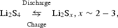 $${\rm L}{{\rm i}_2}{{\rm S}_4}\matrix{ {\scriptstyle{\rm Discharge}} \cr {\leftrightarrows} \cr {\scriptstyle{\rm Charge}} \cr } {\rm L}{{\rm i}_2}{{\rm S}_x},x \sim 2 - 3,$$
 $$4{{\rm S}_3}^{ - 2} + {S_4}^ - - {\rm DIB} {\leftrightarrows} {({{\rm S}_4}^ - )_4} - {\rm DIB} . $$
It is clear that the introduction of organosulfur moieties from poly(S-r-DIB) copolymer into the cathodes improves battery performance. In earlier works, these poly(S-r-DIB) copolymers were found to significantly improve the materials processing relative to elemental sulfur and were readily melt or solution processed into thin films or free standing forms.[Reference Chung, Griebel, Kim, Yoon, Simmonds, Ji, Dirlam, Glass, Wie, Nguyen, Guralnick, Park, Somogyi, Theato, Mackay, Sung, Char and Pyun33, Reference Griebel, Namnabat, Kim, Himmbelhuber, Moronta, Chung, Simmonds, Ngyugen, Mackay, Char, Glass, Norwood and Pyun38] In this study, we examine the morphological ramifications of incorporating the DIB units, which lead to a more homogeneous and higher capacity cathode composite that can subsequently better accommodate the mechanical stresses that arise from the repeating expansions and contractions during charge/discharge cycling. In the following, we discuss morphological variations in the distributions of the conductive carbon nanoparticles in both the poly(S-r-DIB10%)-based and poly(S-r-DIB50%)-based composites and compare, when possible, to the case of the analogous elemental sulfur-based composites.
The secondary electron images in Fig. 2 correspond to uncycled cathodes consisting of the poly(S-r-DIB50%) copolymer-based composites (left column) and poly(S-r-DIB10%) copolymer-based composites (middle column), along with the elemental S8–carbon composite cathode (right column) for comparison. Complementary bright-field and dark-field light microscopy images of the same cathodes are shown in Fig. 1S [Supplementary Information (SI)]. The low-magnification secondary electron images (upper row) display a marked structural transition as the DIB loading increased. The conventional S8-based cathode contains multiple cracks that are approximately 10–20 μm wide [Fig. 2(c)]. As the cathodes have yet to be cycled, these cracks must have developed during the blade coating of the cathode slurry and most likely stem from the significant volume reductions that occur as the coating dries. Constrained by the rigid substrate, this volume reduction induces mechanical stresses in the cathode layer as it dries. These stresses presumably lead to cracks when they exceed the strength of the cathode composite. It is striking that the inverse vulcanization process remarkably improves the mechanical integrity of the as-cast cathode composites; the propensity for cracking is strongly reduced in the cathodes made from the poly(S-r-DIB50%) copolymer which appear to be essentially crack-free [see Fig. 2(a)].
Low-magnification secondary electron images of the pristine composite cathodes (upper row) and overlaid elemental S K-, C K-, and Al K- x-ray maps from a different area of the same corresponding cathode (bottom row). The image (a) and map (d) in the first column correspond to the poly(S-r-DIB50%) copolymer-based cathode, the second column shows the image (b) and map (e) of the poly(S-r-DIB10%) copolymer-based cathode, and the third column shows the image (c) and map (f) of the conventional sulfur–carbon cathode. The scale bars for images and x-ray maps correspond to a length of 100 μm. In the x-ray maps, the elemental distributions of sulfur, carbon, and aluminum from the underlying current collector are shown in orange, green, and red, respectively.
There is also clear evidence of nodular aggregates of carbon particles of the order of 10–100 μm in size randomly distributed across the S8 cathode in the low magnification secondary electron images. The aggregates suggest a strong segregation between the sulfur and carbon as confirmed by the x-ray mapping presented in the bottom row of Fig. 2, where the sulfur domains are colorized in orange, carbon in green, and aluminum (from the supporting current collector foil) in red. The magnitude of these compositional heterogeneities becomes less pronounced as the DIB content increases. At the lowest magnification the secondary electron image of the poly(S-r-DIB50%) composite does not show any signs of large-scale aggregation of the carbon particles. This enhanced compositional uniformity is confirmed with the EDX maps. What is immediately evident is the large-scale compositional heterogeneity in the S8 cathode; there are phase separated domains, rich in either sulfur or carbon, on length scales that approach tens micrometers. However, this large-scale compositional heterogeneity is significantly reduced as the DIB content increases.
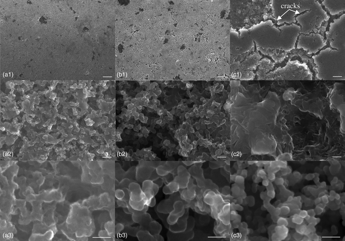
Higher magnification secondary electron images in Fig. 3 of the interfaces between conductive carbon nanoparticles and the elemental sulfur or poly(S-r-DIB) domains provide further insight into mechanisms by which the cathode performance is improved. The composite homogeneity in the DIB containing materials appears to result from an intimate mixing of the sulfur copolymer and C65 carbon nanoparticles (see Fig. 3). This important aspect of how the DIB affects the composite cathode morphology is evidenced at several different length scales. At working magnifications of ×50k (middle row) and ×200k (bottom row), the individual carbon nanoparticles can be seen with diameters ranging from 30 to 50 nm (for size distributions of C65 carbon particles; see Fig. 2S, SI). In the S8 cathode, these nanoparticles form hierarchical and porous aggregates. One can also see a distinct S8 sulfur particle in the center of the image that is devoid of the carbon nanoparticles Fig. 3(c2), demonstrating that elemental sulfur and carbon nanoparticles do not readily mix. By contrast, as the DIB concentration increases one observes a muddled texture over the carbon nanoparticle aggregates. This suggests that the poly(S-r-DIB) copolymers wet the carbon nanoparticles and promote a more intimate mixing of the two components. In comparing the composite cathodes made of the elemental S8 and the poly(S-r-DIB50%) copolymer, especially at the highest magnification of ×200k (the bottom row, Fig. 3), it appears that the poly(S-r-DIB) copolymer is imbedded between the individual carbon nanoparticles. We hypothesize that the benzene ring in the DIB monomer improves the compatibility of the organosulfur copolymer via non-covalent van der Waals bonding with the carbon nanoparticles that possess outer fullerene shells comprising multiple similar benzene-like, hexagonal carbon rings. This will be explored in greater detail below after characterizing the nature of the carbon nanoparticle aggregates.
Higher magnification secondary electron images of the different pristine cathode morphologies, showing the multi-scale architecture of the poly(S-r-DIB50%) copolymer—carbon nanocomposites with different DIB contents. The first column (a1–a3) shows images of the poly(S-r-DIB50%) copolymer-based cathode; the second column (b1–b3) shows mages of the poly(S-r-DIB10%) copolymer-based cathode; and the third column (c1–c3) shows images of the conventional sulfur–carbon composite cathode. The scale bars for the images in the first row correspond to a length of 10 μm, whereas the scale bars for the images in the second row and in the third row correspond to 200 and 100 nm, respectively. The sulfur-rich microparticles in images (b2) and (c2) are marked by dash orange lines.
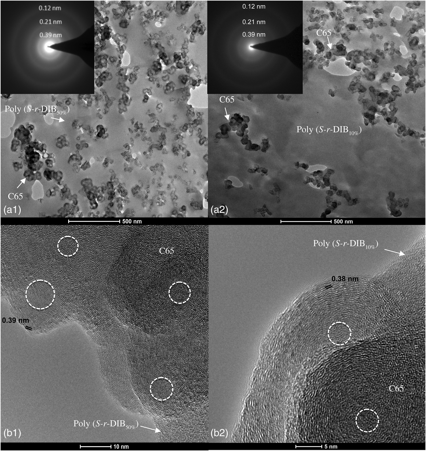
Bright-field TEM (BF-TEM) images of thin sections of the pristine composite poly(S-r-DIB) copolymer-based cathodes [Figs. 4(a1) and 4(a2), respectively] reveal three-dimensional (3D) aggregates of the carbon nanoparticles forming a conductive carbon network embedded in a matrix of the electrochemically active but electrically insulating organosulfur copolymers [Figs. 4(b1) and 4(b2)]. The estimated mean sizes of the carbon clusters were 520 ± 114 nm for the poly(S-r-DIB50%) copolymer-based cathode [Fig. 4(a1)] and 606 ± 125 nm [Fig. 4(a2)] for the poly(S-r-DIB10%) copolymer-based cathode, respectively. The mean diameter of individual C65 carbon particles was determined from the BF-TEM micrograph of a thin cross-section of the poly(S-r-DIB50%)-based cathode in Fig. 4(a1) by counting of 300 particles as d = 38.4 ± 1.0 nm (see Fig. 2Sa, SI). The particle size distributions fit satisfactorily to the normal distribution curve as shown in Figs. 2Sa and 2Sc, SI, respectively. The morphology of the conductive carbon fillers is well resolved due to the low contrast of poly(S-r-DIB) copolymer domains and embedding resin under these imaging conditions. SAED patterns [upper insets of Figs. 4(a1) and 4(a2)] exhibit a series of broad diffuse rings indicating a short-range ordering defined as ordering of the first- or second-nearest neighbors of a carbon atom. The first ring indicates a spacing of 0.39 nm, which corresponds to the partially disordered onion-like fullerene shells. This is close to the natural spacing of the basal planes in graphite and suggests that the carbon nanoparticles have a highly conductive shell. The other two rings at 0.21 and 0.12 nm are typically interatomic dimensions for all amorphous carbon materials. Phase-contrast HRTEM images [Figs. 4(c1) and 4(c2)] show that the carbons are partially coalesced onion-like particles with 3–6 nm ill-defined cores and 10–20 nm outer shells, exhibiting the typical 0.38–0.39 nm graphite-like interlayer spacing. In line with aforementioned SAED data and EELS analyses [see below Figs. 5(g), 5(l), and 3S, SI], this suggests that the particles with electron conductive graphite-like shells form a percolated and presumably conductive network through the cathode matrix. In the presence of the copolymer or sulfur, the conductive aggregated carbon particles likely form electrochemically active interfaces where charge generation and transfer could occur during cycling. It was quite difficult, however, to prepare similar ultramicrotomed thin sections of the S8 cathodes (images not shown) because of the poor integrity of these composite films. This qualitatively points to poor cohesion between conductive carbon nanoparticles and the elemental sulfur.
BF-TEM images of thin sections of the S-r-DIB50% copolymer-based cathode (a1) and the S-r-DIB10% copolymer-based cathode (a2), respectively, showing 3D mesoscale networks of aggregated 30–60 nm conductive carbon particles (Timcal Super C65) interconnected with the organosulfur copolymers. The SAED patterns [upper insets in (a1) and (a2)] display broad diffuse rings indicating a short-range ordering as discussed in the text. HRTEM images of the S-r-DIB50% copolymer-based cathode (b1) and the S-r-DIB10% copolymer-based cathode (b2) show poly(S-r-DIB)–carbon interfaces and partially coalesced C65 carbon nanoparticles displaying 3–10 nm ill-defined cores, marked by dash white line and shells, with graphite-like 0.38–0.39 nm interlayer spacing.
(a, f) HAADF STEM and (b–e, g, h) STEM/EDX/EEL SI of ultrathin sections of the poly(S-r-DIB50%) copolymer-based cathode and poly(S-r-DIB10%) copolymer-based cathode, respectively. Red rectangular boxes in (a) and (f) mark the areas where EDX and EELS analyses were performed; (b, c) x-ray maps of carbon (b) and sulfur (c) for the section of the poly(S-r-DIB50%) copolymer-based cathode, red cross 1 marks the point where the x-ray spectrum shown in Fig. 3Sa, SI was acquired; (d) STEM-EELS spectral image for the section of the poly(S-r-DIB50%) copolymer-based cathode, red box 1 marks the point where the EEL spectrum shown in Fig. 3Sb, SI was acquired; (e) overlaid carbon C K and sulfur S L 2,3 EELS maps for the section of the poly(S-r-DIB50%) copolymer-based cathode; (g) drift-corrected EDX spectral line profile along the orange line shown in (f) for the section of the poly(S-r-DIB10%) copolymer-based cathode, the x-ray spectrum shown in Fig. 3Sc, SI was acquired in the point 1 marked by red cross in (f) and black line in (g), respectively; (h) overlaid carbon C K and sulfur S L 2,3 EELS maps for the section of the poly(S-r-DIB10%) copolymer-based cathode, red box marks the point where the EEL spectrum shown in Fig. 3Sd, SI was acquired.
Returning to the discussion about the improved compatibility, the muddled textures in the high magnification FESEM images in Fig. 3 suggested that the poly(S-r-DIB) copolymers are able to wet the carbon nanoparticles. This is supported by the BF-TEM and HRTEM images in Fig. 4. The regions between and in contact with the percolated carbon nanoparticle aggregates appear to be poly(S-r-DIB) domains. This is corroborated through spatially correlative elemental analyses of HAADF-STEM images coupled with EDX and EEL spectroscopies performed in the same areas. In HAADF STEM, the image intensity varies monotonically with a mean atomic number, thus making possible to visualize lateral distributions of poly(S-r-DIB) copolymer phases [Figs. 5(a) and 5(f)]. Morphology evidence of the enhanced chemical compatibility at these molecular length scales again points to stronger cohesion between copolymers and conductive carbon nanoparticles in the poly(S-r-DIB)–carbon composite cathodes. Consistent with this notion, spatially correlated EDX/EEL elemental maps reveal local distributions of sulfur in these interfacial regions near the carbon nanoparticles at the sub-5 nm length scales and within the copolymer matrix as well. Together with FESEM/EDXS analyses (see Figs. 2 and 3), the collected STEM imaging and spectroscopy data conclusively demonstrate that the film uniformity of poly(S-r-DIB) copolymer-based cathodes arise from compatibilization of the sulfur copolymer and carbon fillers at the sub-5 nm length scales, particularly when compared with the gross morphology of conventional S8–carbon cathodes. HAADF-STEM imaging of thin sections of both the poly(S-r-DIB50%)-based and poly(S-r-DIB10%)-based composite cathodes confirms that the organosulfur copolymers form nearly conformal coatings with intimate contacts around the conductive carbon nanoparticles for both compositions. The poly(S-r-DIB) copolymers appear to be in wetting contact with the C65 carbon nanoparticles indicating intimate contacts between the components at potentially electrochemically active interfaces during cycling.
In addition to the elemental composition maps, EELS was employed to probe the electronic states and bonding within different domains. Figures 4Sa and 4Sb, SI show HAADF-STEM images of ultrathin cross-sections of the poly(S-r-DIB50%) and poly(S-r-DIB10%) cathodes, respectively, combined with a low-loss EELS analyses in selected spots from different regions of the microstructures (Fig. 4Sc, SI). Spectra taken from locations 1, 2, 3, and 4 in Figs. 4Sa and 3Sb are shown in Fig. 4Sc, SI. The spectra reflect excitations of outer-shell (valence) electrons within the probed material that arise from the inelastic scattering of the electron beam. For insulating poly(S-r-DIB) composite cathodes, the valence electron energy-loss (VEEL) spectra from 0 to 30 eV are dominated by the plasmons and excitons that involve collective excitations of electron–hole pairs. This leads to a net displacement at a given wavelength of the full momentum-dependent electronic structure of 2s 1/2, 2p 3/2, and 2p 1/2 occupied states (for carbon atoms) and 3s 1/2, 3p 3/2, and 3p 1/2 occupied states (for sulfur atoms), respectively. The low-loss regions exhibits both π and σ + π plasmons as characteristic bonding fingerprints in the 5.6–6.3 eV and at 21.5–25.1 eV ranges, respectively (Fig. 4Sc, SI). The highest values for π and σ + π plasmon losses at 6.3 and 25.1 eV, respectively, are observed in regions that correspond predominantly to the carbon nanoparticles [Fig. 4Sc, spectrum (4), SI]. These strong π plasmon excitations observed along the percolated carbon nanoparticle domains are consistent with domains being electrically conductive pathways. However, strong π plasmons were not evident from any of the sulfur copolymer-rich regions, despite the existence of the benzene moiety in the DIB monomer. This is consistent with the electrically insulating nature of the poly(S-r-DIB) copolymers and reflects the dominance of the σ bonding as compared with carbon nanoparticle regions.
We are also able to discern subtle differences in the bulk σ + π plasmon peak energies between the two different sulfur copolymer compositions. For the poly(S-r-DIB50%) copolymer, the bulk plasmon peak occurs at 22.6 eV [spectrum (1) in Fig. 4Sc, SI], while for poly(S-r-DIB10%) [Spectrum (3) in Fig. 4Sc, SI] the bulk plasmon peak shifts to 21.5 eV. The compositional variations in the bulk plasmon peak position indicate that the nature of the molecular bonding in the copolymer-rich regions changes with composition and suggest that one can employ VEELS to distinguish directly the poly(S-r-DIB50%) phase from the poly(S-r-DIB10%) phase and from onion-like conductive carbons [spectrum (4) in Fig. 4Sc, SI] as well.
In the core-loss region (Fig. 4Sd, SI), the sulfur S L 2,3-edge at 165 eV has a featureless and rounded profile that is likely dominated by atomic effects rather than solid-state band structure and coordination. This leads to a broad maximum delayed by 20 eV beyond the ionization threshold of 165 eV. At energies just above the ionization threshold a centrifugal barrier prevents overlap between the initial 2p 3/2 (L 3) and 2p 1/2 (L 2) electron states and final unoccupied 3d state wavefunctions, particularly for final 3d states with a large angular-momentum quantum number l′. The delayed maximum results from contributions of the angular momentum l′(l′ + 1) term in the radial Schrödinger equation describing corresponding final state radial wavefunction, which causes a maximum to appear in the effective atomic potential (for details, see Ref. Reference Egerton39). The electron loss near-edge structure of the carbon C K-edge at 284 eV (Fig. 4Se, SI) reveals characteristic excitations from 1s to the π* band, corresponding to sp 2 bonding with a sharp peak just above the edge onset typical for graphitic-like outer shells as well as excitations from 1s to the σ band with a broad peak above 291 eV corresponding to sp 3 bonding. Contrary to the low loss, core π excitations are clearly evident for both carbon nanoparticles and poly(S-r-DIB) copolymers. This verifies the presence of the benzene moieties of the DIB monomer in the copolymer-rich regions. When combined with spatially resolved VEELS, the ratios of the sp 2/sp 3 carbon–carbon bonding further corroborate the picture that the fullerene-like carbon nanoparticles form electrically conductive percolated networks. The incorporation of the DIB improves access of this conductive network to the electrochemically active interfaces at the surfaces of electrically insulating poly(S-r-DIB) domains through improved compatibility. It is hypothesized that this results in an increased utilization of the electrochemically active sulfur in the cathode and retention of this active material upon cycling. This is nominally consistent with through-plane dc conductivity measurements that show a slight increase in electrical conductivity of the cathode as the fraction of DIB content increases, despite the fact that DIB itself is electrically insulating (Fig. 5S, SI). This supports notion that incorporation of DIB improves the electrical percolation of the carbon nanoparticles in the composite electrodes.
Earlier we noted that increasing the DIB content reduced the propensity for shrinkage-induced cracking while the cathode composites dried. This suggests that there is also a benefit of adding the DIB from the point of view of improving mechanical stability. To evaluate the effects of organosulfur-DIB compatibility with conductive carbon fillers on cycle life, FESEM images of the cathodes in their discharged state are used to interrogate the integrity of composite films as a function of cathode cycling. In conventional Li–S batteries, capacity fade is attributed to mechanical detachment of the cathode from the current collector due to irreversible build-up of lower lithium sulfide discharge products (Li2Sx, where x ≈ 2–3) that block the active material during the prolong cycling. The unevenly distributed Li2S deposits, often referred to as “slate,” can exacerbate the cracks incurred during fabrication due to mechanical stresses induced by repeated cycling. Cathode cracks foreshadow irreversible Li2S deposition and therefore correlate with the lowered capacity retention. Figures 6 and 7 compare secondary electron images and x-ray maps of discharged, solvent-rinsed cathodes made from either the sulfur copolymer with 50% by mass DIB at 30 cycles, 10% by mass DIB at 120 cycles and elemental sulfur at 30 cycles, respectively. The conventional S8 cathode sample [Figs. 6(c) and 7(c1–c3)] reveals the deep cracks spreading throughout the cathode and extend down to the aluminum current collector. These reflect an integral effect of severe stresses incurred during initial drying of the cathode followed by additional damage incurred through multiple deposition/dissolution cycles. These images exemplify the limitations of sulfur for capacity retention and long-term performance. The secondary electron images of a poly(S-r-DIB50%) copolymer-based cathode [Figs. 6(a) and 7(a1)], however, reveal almost crack-free morphologies over large areas at lower magnifications while preserving the extended meso- and nanoscale porosity at the higher magnifications, despite the extended cycling [Figs. 7(a2) and 7(a3)]. We have also observed remarkably reduced cathode degradation at 120 cycles with 10% by mass DIB copolymers [see Figs. 7(b1)–7(b3)]. These observations correlate well with the electrochemical performance of the poly(S-r-DIB10%) copolymer-based compositecathode retaining high capacity of 1005 mAh/g at 100 cycles (Fig. 1).
Low-magnification secondary electron images of the cycled cathodes (upper row) and complimentary overlaid S K-, C K-, and Al K- EDX x-ray maps from the same areas (bottom row) of the cycled discharged cathodes. The first row represents images obtained at the same magnification as images of pristine cathodes shown in Fig. 2. The scale bars for images and x-ray maps correspond to a length of 100 μm. The first column (a, d) shows images of the poly(S-r-DIB50%) copolymer–carbon cathode after 30 cycles; the second column (b, e) shows images of the poly(S-r-DIB10%) copolymer-carbon cathode after the 120 cycles; and the third column (c, f) shows images of the conventional sulfur–carbon cathode after 30 cycles, all in the discharged state. Elemental distributions of sulfur, carbon, and aluminum (from a current collector), are shown in the maps in orange, green, and red, respectively.
Secondary electron images of the cycled cathodes: (a1–a3) the poly(S-r-DIB50%) copolymer-based cathode discharged after 30 cycles; (b1–b3) the poly(S-r-DIB10%) copolymer-based cathode discharged after 120 cycles; and (c1–c3) the conventional sulfur–carbon composite cathode discharged after 30 cycles. Similarly to images of pristine cathodes in Fig. 3, the scale bars for the images in the first row correspond to a length of 10 μm, whereas the scale bars for the images in the second row and in the third row correspond to 200 and to 100 nm, respectively. The poly(S-r-DIB) copolymer-based cathodes show reduced cracking, uniform utilization, and distribution of formed polysulfides (b1) even after 120 cycles. The conventional S8-based cathode exhibits multiple cracks (c1), highly non-uniform utilization already after 30 cycles; needle-like crystallites of an encapsulated LiTFSI imide salt (c2) were found occasionally. The morphological and structural differences between the cycled poly(S-r-DIB10%) copolymer-based cathode and the conventional cathode strongly correlate with their electrochemical performance.
Admittedly the end result of the inverse vulcanization approach described here, increasing both the chemical homogeneity as well as the physical–mechanical stability and integrity of the cathode composite through the utilization of the high molecular mass poly(S-r-DIB) copolymers, is not unlike competing strategies which utilize some sort of a core–shell nanostructure to encapsulate the sulfur into nanoscale domains. Both approaches reduce large-scale heterogeneity in the cathodes. However, the mechanism by which this is accomplished is fundamentally different. The simple one pot mixing approach of blending the cathode components with a high molecular mass poly(S-r-DIB) copolymer has several processing advantages. The fact that electrochemical reactions in both the low- and high-voltage plateaus are so similar between the elemental sulfur systems and the organosulfur systems described here then raises an intriguing question. This suggests that upon discharge these organosulfur compounds are being broken down into the same low molecular mass lithium sulfides. This is validated by the similarity in cyclic voltammetry curves for the organosulfur reactions in comparison with elemental sulfur.[Reference Chung, Griebel, Kim, Yoon, Simmonds, Ji, Dirlam, Glass, Wie, Nguyen, Guralnick, Park, Somogyi, Theato, Mackay, Sung, Char and Pyun33] What's striking is the extreme cycleability of the poly(S-r-DIB)-based composite cathodes. Does this then imply that the high molecular mass organosulfur polymers reform upon charging? The FESEM images of the cycled organosulfur cathodes in Fig. 7 support the notion that the cathode morphology does not undergo dramatic changes upon cycling. However, the nature of how the polymerized form of the poly(S-r-DIB) copolymers changes through charge and discharge process remains an open and intriguing question. Future studies by this team are aimed at answering this question.
Conclusions
In this paper, we identify the morphological and compositional effects of replacing elemental sulfur with electrochemically active high molecular mass poly(S-r-DIB) copolymers in the composite cathodes for high-energy density Li–S batteries. As a part of an emerging class of electroactive polymers, the poly(S-r-DIB) copolymers synthesized recently via inverse vulcanization of molten sulfur have proven to be effective at both increasing power density and enhancing capacity retention upon cycling in comparison with traditional Li–S batteries based on elemental sulfur. The benefits of utilizing the organosulfur copolymer on the morphology of the composite cathode are twofold. First, using FESEM, HRTEM, and STEM imaging and spatially correlative EDXS/EELS analyses, we demonstrate that the presence of the DIB moieties in the copolymers significantly improves the compatibility between the percolated conductive onion-like carbon nanoparticles and the electrochemically active sulfur-containing domains, leading to an intimate mixing of these components at a much finer length scale down to the sub 5 nm. This increases the effective interface between the electrically conductive pathways and domains of the electrochemically active poly(S-r-DIB) copolymers responsible for charge generation and transfer. Furthermore, the compositional variations in the σ + π bulk plasmon peak position indicate that the nature of the molecular bonding in the poly(S-r-DIB) copolymer-rich regions changes with composition and suggest that one can use VEELS to distinguish directly the poly(S-r-DIB50%) phase from the poly(S-r-DIB10%) phase and from conductive carbons as well.
Second, the improved compatibility and homogeneity between the components also appears to create a unique hierarchical cathode morphology that is electrochemically and mechanically more robust. As a result, the pristine, as-cast poly(S-r-DIB) copolymer-based composite cathodes exhibit significantly reduced levels of drying-induced cracking and extended multi-scale porosity that appears to persist as a function of cycling. Taken together, these affects lead to both increased power capacity and enhanced cycle life over traditional Li–S batteries formulated with elemental sulfur. As an outlook based on demonstrated improvements in both the electrochemical performance and mechanical stability, the introduction of advanced poly(S-r-DIB) copolymers evidently shows potential for a technology breakthrough that will enable to develop the next generation of long-cycle life light-weight high-energy density Li–S batteries for emerging applications.
Supplementary materials
For supplementary material for this article, please visit http://dx.doi.org/10.1557/mrc.2015.41
Acknowledgments
The authors acknowledge the ACS-PRF (51026-ND10), the NSF (CHE-1305773), the WCU Program through the NRF of Korea funded by the Ministry of Education, Science and Technology (R31-10013) for support of this work. V.P.O. acknowledges the support by National Institute of Standards and Technology (Award No 70NANB12H164). K.C. acknowledges the support from NRF for the National Creative Research Initiative Center for Intelligent Hybrids (2010-0018290).