I. INTRODUCTION
Grain boundaries (GBs) play a critical role in the mechanical properties of materials in that they can act as barriers or initiators of dislocation activities. Dislocations can be absorbed, piled-up, reflected, transmitted, or emitted into or from GBs based on the crystallographic nature and the evolving local properties of the GBs and adjacent grain interiors. The dislocation structures in the GB are very different than those in the grain interior due to various types of partial dislocations and dislocation absorption and accumulation that can arise from GB misorientations.Reference Gemperle, Gemperlova and Zarubova1
Transmission electron microscopy (TEM) experimental observations have clearly indicated that dislocations can interact with GBs in different ways through direct transfer, absorption, or transmission across the GB with residual GB dislocations and pile-ups that can result in dislocation emission or the nucleation of intergranular cracks. From these observations, several criteria on dislocation transmission have been proposed for these complex processes.Reference Clark, Wagoner, Shen, Lee, Robertson and Birnbaum2–Reference Lagow, Robertson, Jouiad, Lassila, Lee and Birnbaum6 For example, Lee et al. have proposed three criteria for dislocation transmission: (i) the angle between the lines of intersection between the GB and each slip plane must be a minimum, (ii) the magnitude of the Burgers vectors of the dislocations that remain in the GB must be a minimum, and (iii) the resolved shear stress on the outgoing slip system must be a maximum. These three criteria have been used to understand single-dislocation transmissions and rationalize multiple dislocation activities.Reference Lee, Robertson and Birnbaum7–Reference Gemperlova, Jacques, Gemperle, Vystavel, Zarubova and Janecek9
Computational simulations have also provided insights of these GB activities on different physical scales. Molecular dynamics (MD) simulations have shown that GBs can act as sinks and sources of dislocations.Reference Schiotz10, Reference Van Swygenhoven, Derlet and Froseth11 Dislocations can be absorbed in the GB causing pile-upsReference Schiotz10, Reference Yamakov, Wolf, Phillpot and Gleiter12 and cross-slip.Reference Yamakov, Wolf, Phillpot and Gleiter12 These MD methods provide insights that may not be possible with TEM in-situ observations on the nanoscale. But, severe limitations on time and length scales may render these simulations ineffective on the microstructural physical scale that pertains to the inelastic behavior of crystalline aggregates.
Finite-element models (FEMs) and different crystalline plasticity formulations have provided further insights on GB behavior. Ashmawi and ZikryReference Ashmawi and Zikry13 have introduced interfacial GB regions to track slip and dislocation-density transmissions and intersections for a dislocation-density–based crystalline plasticity formulation. Other investigatorsReference Dewald and Curtin14–Reference De Koning, Kurtz, Bulatov, Henager, Hoagland, Cai and Nomura16 have coupled FEM with MD formulations for a multiscale approach.
Desired material properties of most engineering crystalline materials can be potentially obtained by controlling the microstructural aspects of GB behavior. The mechanical, physical, and chemical properties of the GBs can be optimized as a function of the spatial orientation and the crystallography of each grain. There are infinite choices of GB planes and misorientations between adjacent grains. Well-established microscopy studiesReference Garbacz and Grabski17, Reference Garbacz and Grabski18 have shown that these boundaries consist of atomic misfit regions and associated GB ledges. A well-known method that defines this phenomena in GBs is called coincident site lattice (CSL) method.Reference Randle19 It provides a class of GBs with different misorientations that can be used to investigate GB behavior.
For example, Σ1 is a low-angle CSL GB. For this CSL GB, various experiments have indicated that dislocation transmission can easily occur and that there are no dislocation pile-ups in the GB region.Reference Zhang, Wang and Eckert20–Reference Ohmura, Minor, Stach and Morris22 This may be due to that the slip planes of the neighboring grains are mostly coplanar and the slip directions of the neighboring grains are mostly collinear with minor deviation so that the energy barrier for dislocation transmission is rather low, which would make dislocation transmission more likely to occur. Furthermore, the low GB energy of Σ1 GBs may inhibit intergranular fracture.
Σ3 GBs are another type of CSL GBs that usually have a lower GB energy. Experiments and simulations have also shown that one of the dominant interactions between dislocations and GBs for face-centered cubic (f.c.c.) systems with Σ3 GBs is GB dislocation absorption.Reference Couzinie, Decamps and Priester23–Reference Qiao and Argon28 This absorption could be due to lattice dislocations dissociating into Shockley partial dislocations in the GB region. Dislocation transmissionReference Lee, Robertson and Birnbaum3, Reference Poulat, Decamps and Priester26 has also been widely observed for Σ3 GBs. This could be due to potential available coplanar slip planes between neighboring grains in Σ3 GBs. MD simulations of a Σ3 GBReference Spearot, Jacob and Mcdowell29 indicate that the GB can also act as a source of dislocation nucleation. There were no observable pile-ups in crystalline materials with Σ3 GBs. For Σ3 GBs, the misorientation of [111]/60° is generally chosen since it offers various coplanar slip planes between adjacent grains.
For many high-angle GBs in which there are no coplanar slip planes and collinear slip directions, dislocations were usually observed to pile-up in the GB resulting in intergranular cracks.Reference Lin and Pope30–Reference Shi and Zikry34 Σ17b is a typical high-angle GB with a misorientation of [110]/86.63°.
These three CSL GBs provide a representative class of GB that can be used to investigate different behavior. Σ1 GBs have coplanar slip planes and collinear slip directions with minor deviation in all 12 slip systems, Σ3 GBs have several coplanar slip planes, and Σ17b GBs have no coplanar slip planes and collinear slip directions.
Hence, it is essential to understand and predict how different GB misorientations affect behavior at the relevant microstructural scale. In this article, a methodology based on a multiple-slip dislocation-density crystalline formulation and specialized finite-element approaches is introduced to predict GB behavior. This approach is used to model and understand the behavior of bicrystals with a representative class of CSL boundaries that span different orientations. As a part of this framework, a dislocation-density grain–boundary interaction (DDGBI) scheme between GBs and adjacent grain interiors has been developed. This scheme is based on accounting for three interrelated processes: dislocation-density absorption, emission, and transmission. A conservation law for dislocation density is used to determine the balance dislocation activities within GB regions. A step-by-step illustration of the scheme is given, and predictions are obtained for different CSL GBs Σ1, Σ3, and Σ17b GBs, which represent different types of CSL boundaries, such that detailed knowledge of GB activities can be understood and characterized within the scheme of coupling the balance law with the dislocation-density–based crystalline plasticity formulation.
This article is organized as follows: the crystalline plasticity constitutive formulation is presented in Sec. II that includes the computational approach and the proposed DDGBI scheme; computational results and discussions are presented in Sec. III that includes the process to illustrate the DDGBI scheme and comparisons between different CSL bicrystal models; a summary of the significant results is given in Sec. IV.
II. CONSTITUTIVE FORMULATION
A. Multiple-slip dislocation-density–based crystalline formulation
In this section, a constitutive formulation for the finite deformation of rate-dependent multiple-slip crystal plasticity is outlined. The detailed presentation of this constitutive formulation is given by Zikry and Kao.Reference Zikry and Kao35
It is assumed that the deformation gradient can be decomposed into elastic and plastic components, starting from the decomposition of the velocity gradient Vi,j into symmetric and antisymmetric parts as

where Wij is the antisymmetric part representing the spin tensor, and Dij is the symmetric part representing the deformation rate tensor. It is assumed that the spin tensor Wij and deformation rate tensor Dij can be further decomposed into elastic and plastic parts as


The superscript “*” means that the elastic part, and the superscripts “p” denotes the plastic part. Wij* represents the rigid body spin. The elastic components of the velocity gradient Dij* correspond to the elastic lattice distortion, and the inelastic parts are defined in terms of the crystallographic slip rates as
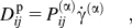
and
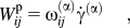
where α is summed over all slip systems, and the tensors Pij (α) and ωij (α) are defined in terms of the unit normals and the unit slip vectors as


For a rate-dependent formulation, the slip-rates are functions of the resolved shear stress and the reference shear stress on each slip systems in a power law form of

where  is the reference shear strain rate that corresponds to a reference shear stress
 , m is the rate sensitivity parameter, and for most of the metals m is close to 100 at room temperature. The reference shear stress is a modification of widely accepted classical forms that relate the reference shear stress to a square-root dependence on the immobilized dislocation density as
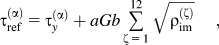
where b is the magnitude of burgers vector, G is the shear modulus, τy (α) is the static yield stress, and a is the interaction coefficient and generally has a magnitude of unity.
The resolved shear stress τ (α) on the αth slip system is given in terms of the Cauchy stress σij as
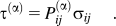
For a deformed material, it can be assumed that the dislocation structure of total dislocation density ρ (α) can be additively decomposed into two components: immobile dislocation density  and mobile dislocation density
 as

During an increment of strain, the dislocation density generates (denoted by ρ (α)+) and annihilates (denoted by ρ (α)−). It is assumed that there exist balance laws to account for dislocation generation, interaction, trapping, and recovery as
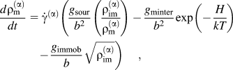
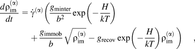
where g sour is a coefficient pertaining to an increase in the mobile dislocation density due to dislocation sources; g minter is a coefficient related to the trapping of mobile dislocation due to forest interactions; g recov is a coefficient related to the rearrangement and annihilation of immobile dislocations; g immob is a coefficient pertaining to the immobilization of mobile dislocations; H is the activation enthalpy; and k is the Boltzmann constant. As these evolutionary equations indicate, the dislocation activities related to recovery and trapping are coupled to thermal activation.
B. DDGBI scheme
In this section, a DDGBI scheme is presented to account for the GB dislocation-density activities. It is assumed that the dislocation-density interactions occur between slip systems on each side of the GB interface. Based on the single-transmission criteria by Clark et al.,Reference Clark, Wagoner, Shen, Lee, Robertson and Birnbaum2 a transmission criterion for multiple slip is proposed as follows:
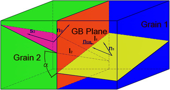
Criterion 1. For slip system α in one grain and slip system β in the neighboring grain, the transmission factor Mαβ between them should be greater than a critical threshold M cr. A transmission factor is proposed based on two components. The first one is the angle A (Fig. 1), i.e., the angle between the intersection lines of the slip planes and GB planes; the second part is the angle B between slip directions of these two slip systems. Hence, the transmission factor Mαβ can be denoted as

Intersection angles α between slip planes and grain–boundary (GB) planes.

where

and

Criterion 2. The ratio of resolved shear stress to the reference shear stress of the outgoing slip system (stress ratio) should be greater than a critical value c cr, which is approximately 1.
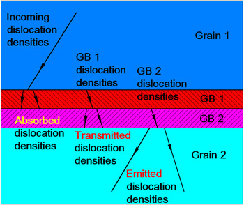
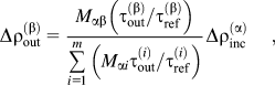
If these transmission criteria are satisfied, a dislocation density can emit from a higher dislocation-density region to a lower dislocation-density region. It is assumed that the dislocation densities will be redistributed according to these transmission factors as shown in Fig. 2. Based on this, a balance of dislocation densities due to these different dislocation-density interactions Δρout(β) can be defined as
Dislocation-density redistribution according to the transmission factors and resolved shear stress. When dislocation-density absorptions occur, mobile dislocation density is immobilized in the GB; emission occurs when the immobile dislocation density is mobilized into the grain interior; transmission occurs when immobile dislocation density transmits through GB.

where α is an incoming slip system, β is an outgoing slip system,  is the corresponding resolved shear stress, and
 is the reference shear stress of the outgoing slip system β. m is the number of all possible outgoing slip systems, and Mαβ is the transmission factor between the incoming and outgoing slip systems.
When dislocation densities emit from one element to the other, a balance for the dislocation densities can be obtained by considering dislocation-density conservation.Reference Aifantis36
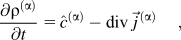
where

where  represents the flux of dislocation densities in slip system α; A is the area of integration;
 is the GB surface normal; Δρ (α) is the summation of the dislocation-density changes in the domain indicated by Eq. (12); and
 represents the generation, immobilization, or annihilation of dislocations densities.
 is given by the statistical distribution of the immobile and mobile dislocation densities from Eqs. (14a) and (14b).
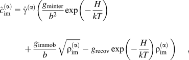
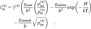
So that the evolution of dislocation densities is updated as
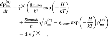
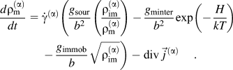
Dislocation-density activities can occur in the GB interface and GB interior interfaces (Figs. 2 and 3). In the proposed GB representation, we assume that dislocation-density “transmission” occurs when immobile dislocation densities transmit through the GB interfaces to compatible slip systems in the neighboring grain. Dislocation-density “absorption” occurs when mobile dislocation densities from the grain interior transmit into the GB but do not transmit out of it. In this case, all of the mobile dislocation densities are then immobilized to immobile dislocation densities and are assumed to be absorbed in the GB. Some of these immobile dislocation densities in the GB regions may “pile-up,” but as the deformation evolves can activate neighboring slip systems. This can result in dislocation-density emission in which the immobile dislocation densities in the GB become mobile dislocation densities and “emit” into the neighboring grain. Hence, all three processes of transmission, absorption, and emission can occur simultaneously on different slip systems within the GB region and between neighboring grains.Reference Shi and Zikry34, Reference Shi and Zikry37
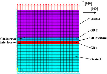
Finite-element mesh, loading, and boundary conditions of the bicrystal.

C. Computational methods
The total deformation rate tensor Dij and the plastic deformation rate tensor Dij p are needed to update the material stress state. The method used here is the one developed by ZikryReference Zikry38 for rate-dependent crystalline plasticity formulations, and a brief outline will be given here. An implicit FEM is used to obtain the total deformation rate tensor Dij. To overcome numerical instabilities associated with stiffness, an adaptive explicit–implicit method is used to obtain the plastic deformation rate tensor Dij. An explicit fifth-order Runge–Kutta method is used most of the times, and when numerical stiff occurs, the computation scheme automatically switches to the implicit backward Euler method. This adaptive numerical scheme is also used to update the evolutionary equations for the mobile and immobile dislocation densities and the resolved shear stress.
III. RESULTS AND DISCUSSIONS
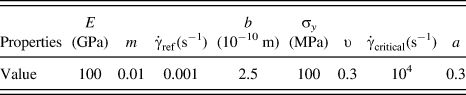
The multiple-slip crystal plasticity dislocation-density–based constitutive formulation and the finite-element computational scheme are used to investigate material deformation mechanisms associated with low- and high-angle CSL boundaries in f.c.c. copper bicrystals. The Σ1, Σ3, and the Σ17b CSL GB orientations were chosen to study the deformation modes and failure mechanisms in materials separated by these CSL boundaries. These CSL GBs were chosen because they are representative in GB structures. The misorientations of these CSL GBs are given by Table I(a). Coincident site lattice grain boundary misorientations used in the simulation. Material properties of copper.
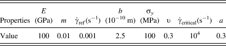
The material properties that are used here [Table I(b)] are representative of crystalline copper (see, e.g., ZikryReference Zikry38). The initial immobile dislocation density ρ ims was chosen as 1010 m−2, and the initial mobile dislocation density ρ ms was chosen as 107 m−2. The values of the initial and the saturated dislocation densities are representative of copper.Reference Mughrabi39 Based on the scheme developed by Zikry and Kao,Reference Zikry and Kao40 we have obtained the coefficient values needed for the evolution of the immobile and mobile densities and the specified material properties. These values are g minter = 5.53, g recov = 6.67, g immob = 0.0127, g sour = 2.7 × 10⁻⁵.
The bicrystal model has two grains, and their interface is the CSL GB region. Due to limited understanding on the relation of GB width and GB misorientation, it is assumed here that the GB width is uniform (10% of the grain size) for the different CSL boundaries. All models have the same boundary conditions and loading conditions; symmetry boundary conditions are applied, and a displacement loading was applied on the top surface. To validate the finite-element convergence of this scheme, we refined the mesh until we achieved convergence with 1,600 four-noded quadrilateral elements (Fig. 3).
A. Dislocation-density transmission
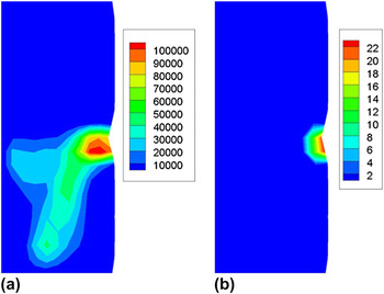
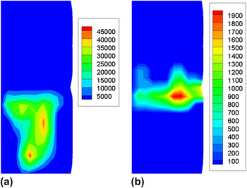
First, a comparison is made between an aggregate without the DDGBI scheme and one with the DDGBI scheme to show the effect of this scheme. The dislocation-density evolutions of a Σ3 bicrystal are presented in Figs. 4–6 at a nominal strain of 20%. The immobile dislocation density of the most active slip system  is shown in Figs. 4(a), 5(a), and 6(a), and the immobile dislocation density of a less active slip system
 is shown in Figs. 4(b), 5(b), and 6(b). At the GB, the resolved shear stress is 0.85τ ref for the less active system. The transmission factor between these two slip systems is equal to 0.7, which indicates that there is a high possibility of dislocation-density transmission through the GB. At the GB, the dislocation densities on the active slip system [Fig. 4(a)] are much higher than the less active slip system [Fig. 4(b)]. If there is no interaction mechanism between the GB and the dislocation densities due to the reference stress being below the critical stress, the dislocation densities of the less active slip system of the neighboring grain remain the same even though there is high possibility of dislocation transmission at the boundary in this situation.
Dislocation density without transmission in the Σ3 bicrystal at 20% nominal strain. (a) The immobile dislocation densities of the most active slip system  and (b) the immobile dislocation densities of a less active slip system
 with high resolved shear stress.

Dislocation-density transmission in the Σ3 bicrystal at 20% nominal strain. (a) Immobile dislocations of the most active slip system  and (b) immobile dislocation density of a less active slip systems
 with high resolved shear stress.

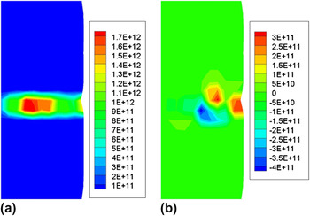
The flux of dislocation densities in the Σ3 bicrystal at 20% nominal strain. (a) The dislocation-density flux of the slip system  and (b) the dislocation-density flux of the slip system
 .

Conversely, the DDGBI scheme indicates that dislocation transmission is possible. The higher dislocation densities associated with the most active slip system can be transmitted into the less active slip systems when the DDGBI scheme is applied. Upon dislocation transmission, there is a significant decrease of immobile dislocation densities of the most active slip system  [Fig. 5(a)] and a consequent increase of immobile dislocation densities in the less active slip system
 [Fig. 5(b)]. The dislocation-density transmission can be further monitored by the flux of dislocation densities going in and out of the GB elements. The dislocation-densities flux of the most active slip system is shown in Fig. 6(a), and the contour of the dislocation-densities flux in the less active slip system is shown in Fig. 6(b). In these figures, positive flux indicates that the dislocation densities are emitting from GB, while a negative value indicates that the dislocation densities are transmitting into GB. It can be seen that the most active slip system
 is emitting dislocation densities from GB at a flux rate of 1.7 × 10¹²/m2 s [Fig. 6(a)]. Slip system
 is simultaneously emitting and absorbing dislocation densities at different regions of the GB as indicated by the changes in the dislocation-density flux for rates that range from −4 × 10¹¹ to 3.5 × 10¹¹/m2 s [Fig. 6(b)].
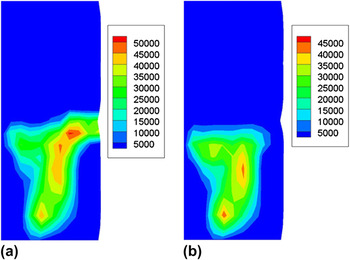
The effects of the above dislocation-density flux shown in Figs. 6(a) and 6(b) can be clearly seen in Figs. 7(a) and 7(b). The dislocation density without conservation is shown in Fig. 7(a), and as seen in comparison with the case that includes conservation, the dislocation density in the GB region is quite different. In the GB region, the immobile dislocation density when the conservation law is used is approximately one-third less than when the conservation law is not used. More significantly, when the conservation law is used, the immobile dislocation-density transmissions are localized near the GB. This localization and GB accumulation do not occur when the conservation law is not used.
Dislocation-density conservation at 20% nominal strain. (a) The immobile dislocation densities of slip system  without applying the conservation law and (b) the immobile dislocation densities of slip system
 when conservation law is used.

B. Dislocation-density absorption and emission
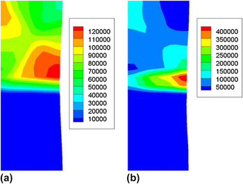
As noted earlier, the GB region can have sources and sinks of dislocation densities. The DDGBI scheme can physically represent these two interactions. For example, Fig. 8(a) shows the immobile dislocation densities of the most active slip system  of a Σ17b GB without dislocation-density absorption, the maximum dislocation density is 1.2 × 10¹⁵ m−2 in the GB region; Fig. 8(b) shows the immobile dislocation densities in the same slip system
 where the dislocation-density absorption is taken into consideration. The maximum immobile dislocation density in the GB region is 4 × 10¹⁵ m−2, which is approximately 2.5 times higher than the case when no DDGBI scheme is used.
Dislocation-density absorption in Σ17b bicrystal at 20% nominal strain. (a) The immobile dislocation densities of slip system  calculated without considering absorption and (b) the immobile dislocation densities of slip system
 calculated with absorption.

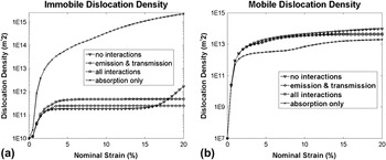
There is a significant dislocation-density absorption in the GB region in which mobile dislocation densities from the grain interior have been absorbed in the right part of the GB region [Fig. 8(b)]. Therefore, when absorption occurs, the mobile dislocation densities in the neighboring region decreases [Fig. 9(b)] and the immobile dislocation densities in the GB increases [Fig. 9(a)]. In these plots, a GB element with the highest values of immobile dislocation densities was chosen, and these values were monitored as function of the nominal strain. This element was generally near the center of the GB region. Several interactions are given in Fig. 9 for absorption, emission, and transmission of immobile and mobile dislocation densities. Hence, when dislocation-density emission is accounted for, the immobile dislocation densities in the GB element decrease [Fig. 9(a)] and the mobile dislocation densities in its neighboring grain interior element increase [Fig. 9(b)]. Furthermore, as the curves indicate, the immobile dislocation densities increase and the mobile dislocation densities decrease as the absorption occurs.
Different GB interactions and dislocation-density behavior at 20% nominal strain. (a) Semi-logarithmic plot of immobile dislocation-density development in one of the most active GB elements in the Σ17b bicrystal and (b) semi-logarithmic plot of mobile dislocation-density evolution in the neighboring element in Σ17b model.

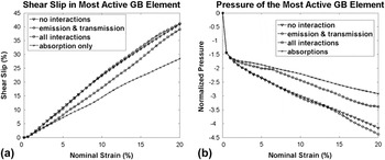
Dislocation-density activities in the GB can affect different deformation patterns. For example, based on activities in the most active GB element, the absorbed dislocation densities can impede shear slip [Fig. 10(a)], and these absorbed dislocation densities distort the GB region with high GB pressures [Fig. 10(b)]. The pressures in the GB region attain a maximum value, i.e., approximately 40% higher when there is dislocation-density absorption than for the case when there is only emission.
Different GB interactions in most active element between GB and dislocation densities of Σ17b model at 20% nominal strain. (a) The evolution of shear slip in an active GB element. (b) Pressure in the same active GB element.

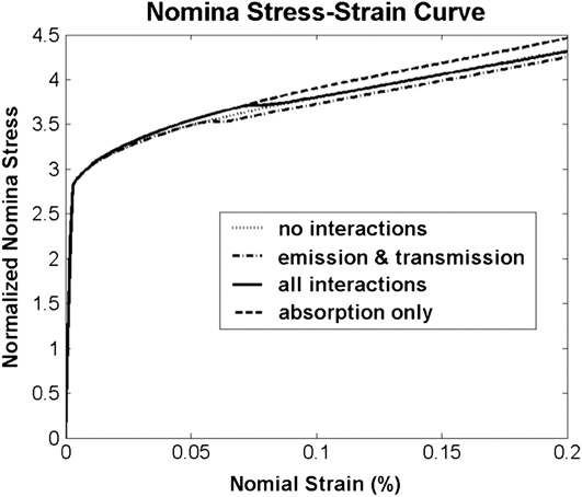
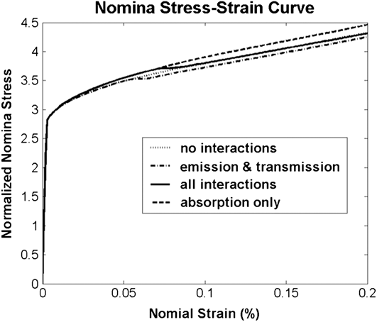
The normal stress increases when the immobile dislocations are absorbed in the GB, and the normal stress decreases when dislocation-density emission occurs. The dislocation-density emission and absorption are competitive processes that work simultaneously during deformation. High absorption may cause dislocation-density pile-ups and increases in stress, and dislocation-density emission may release the stress accumulated by absorption. As we can see from Fig. 11, when only absorption is considered, the normal stress of the material is higher; when the dislocation-density emission is accounted for, the normal stress is lower by a factor of 5% than what is predicted without the DDGBI scheme.
The nominal stress comparison for different schemes for the Σ17b bicrystal at 20% nominal strain.
C. Varying CSL GBs
Different CSL boundaries have different misorientation angles, which imply different GB structures, energies, and dislocation-density activities. Numerous experimental investigationsReference Gemperle, Gemperlova and Zarubova1, Reference Lee, Subramanian, Robertson and Birnbaum41, Reference Zhong, Xiao, Zhang, Shan, Wang and Yang42 have shown that different CSL boundaries result in different deformation modes. Hence, bicrystals with Σ1, Σ3, and Σ17b CSL boundaries [Table I(a)] were investigated to understand and quantify these effects.
1. Σ1 GBs
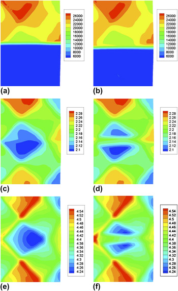
The low energy of Σ1 CSL GB makes it insensitive to intergranular cracking.Reference Zhang and Wang43, Reference Robertson, Lee and Birnbaum44 Coplanar slip planes and collinear slip directions between grains can also enhance dislocation-density transmission. Therefore, bicrystals with Σ1 GBs would have minimal dislocation-density absorptions within the GB region. Based on the simulations, at 20% nominal strain, there are minor differences without [Fig. 12(a)] and with [Fig. 12(b)] the DDGBI scheme for the Σ1 CSL bicrystal. No dislocation-density pile-ups and stress concentration in the GB region were seen in the simulation. The dislocation-density interactions with the DDGBI scheme results in higher immobile dislocation densities of the most active slip system in the GB by approximately 7% in comparison with the case without the DDGBI scheme. When comparing the resolved shear stress [Figs. 12(c) and 12(d)] and Von Mises stress [Figs. 12(e) and 12(f)] in the GB elements, the differences between two methods are negligible. There is a 1.8% increase in resolved shear stress and a 1.2% increase in Von Mises stress when the DDGBI scheme is used. This indicates that for the Σ1 dislocation-density interactions dominated by dislocation-density transmission.
The material behavior of the Σ1 bicrystal at 20% nominal strain. (a) The immobile dislocation densities of the most active slip system  without using the DDGBI scheme; (b) the immobile dislocation densities of the most active slip system
 using the DDGBI scheme; (c) the resolved shear stress of the most active slip system
 without the DDGBI scheme; (d) resolved shear stress of the most active slip system
 with the DDGBI scheme; (e) Von Mises stress without using the DDGBI scheme; and (f) Von Mises stress with the DDGBI scheme.

2. Σ3 GBs
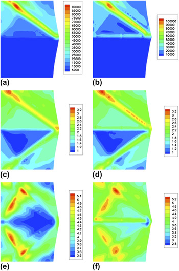
Numerous TEM observations for f.c.c. Σ3 bicrystalsReference Lee, Robertson and Birnbaum3, Reference Lee, Robertson and Birnbaum7, Reference Gemperlova, Polcarova, Gemperle and Zarubova8, Reference Couzinie, Decamps and Priester23–Reference Poulat, Decamps and Priester26, Reference Medlin, Foiles and Cohen45–Reference Schmidt, Finnis, Ernst and Vitek47 have shown that dislocation-density absorption and transmission are the most commonly observed phenomena. Pile-ups in Σ3 GBs are hard to form because Σ3 GBs misorientations ensure that at least one pair of slip planes in neighboring grains are coplanar, which provides an easy path for dislocation densities to transmit, and hence pile-ups are not likely to occur.Reference Gemperle, Gemperlova and Zarubova1, Reference Lee, Robertson and Birnbaum3 From the simulations, there are no predicted dislocation-density interactions in the GB when the DDGBI scheme is not used [Fig. 13(a)]. When the DDGBI scheme is used, the dislocation-density interactions result in higher dislocation densities and stresses in comparison with the case when the DDGBI scheme is not used [Fig. 13(b)]. For the DDGBI case, the immobile dislocation densities of the most active slip system are higher by approximately 50%, and the resolved shear stress [Figs. 13(c) and 13(d)] and Von Mises stress [Figs. 13(e) and 13(f)] are higher by approximately 20% in comparison with the case when the DDGBI is not used. As is also evident from the contours, the deformation patterns are more localized around the GB for the DDGBI case in comparison with the case where the DDGBI is not used, and this is a direct consequence of the competing GB dislocation-density interactions.
The behavior of the Σ3 bicrystal at 20% nominal strain. (a) The immobile dislocation densities of the most active slip system  without the DDGBI scheme; (b) the immobile dislocation densities of the most active slip system
 using DDGBI scheme; (c) the resolved shear stress of the most active slip system
 without the DDGBI scheme; (d) resolved shear stress of the most active slip system
 with the DDGBI scheme; (e) Von Mises stress without the DDGBI scheme; and (f) Von Mises stress with the DDGBI scheme.

3. Σ17b GBs
There are no coplanar slip planes and collinear slip directions in Σ17b GBs. Σ17b GBs have similar properties as other high-angle GBs in which dislocations are not easy to transmit through GBs. Hence, this results in absorption and pile-ups in the GB region with possible intergranular cracks.Reference Zhong, Xiao, Zhang, Shan, Wang and Yang42, Reference Robertson, Lee and Birnbaum44, Reference Van Swygenhoven, Farkas and Caro48
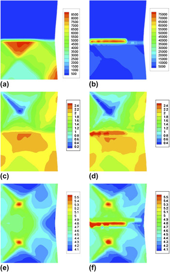
It is shown in Fig. 14 that without the DDGBI scheme there are high dislocation densities in the grain interior. The high dislocation densities are absorbed and piled-up in the GB region as indicated by the DDGBI scheme. This results in high normal stresses in the GB region. For the case without the DDGBI scheme, the immobile dislocation densities in most active slip system in the GB region is approximately 8.5 × 10¹³ m−2 [Fig. 14(a)]. When the DDGBI scheme is used, the immobile dislocation densities in the GB region increases by approximately 780% to 7.5 × 10¹⁴ m−2 [Fig. 14(b)]. Consequently, these GB dislocation-density pile-ups significantly increase the resolved shear stress [Figs. 14(c) and 14(d)] and the Von Mises stress [Figs. 14(e) and 14(f)] in the GB region. The pile-ups of dislocation densities in the GB region in combination with these high stress values can result in intergranular cracks.
The behavior of the Σ17b bicrystal at 20% nominal strain. (a) The immobile dislocation densities of the most active slip system  without the DDGBI scheme; (b) the immobile dislocation densities of the most active slip system
 using DDGBI scheme; (c) the resolved shear stress of the most active slip system
 without the DDGBI scheme; (d) resolved shear stress of the most active slip system
 using DDGBI scheme; (e) Von Mises stress without the DDGBI scheme; and (f) Von Mises stress with the DDGBI scheme.

These predictions are consistent with different experimental observations of dislocation activities in different materials with different GB orientations. It has been observed in numerous experiments that GB behavior differs between different GBs. For low-angle GBs, dislocations transmit without impedance through the GB, and there are very rare cases of dislocation pile-ups. For high-angle GBs without coplanar slip planes and collinear slip directions, dislocations are more likely to be absorbed and piled-up in the GB. For example, in an indentation test of martensitic steel,Reference Ohmura, Minor, Tsuzaki and Morris49 a low-angle GB allows dislocations to transmit through the GB, and plastic slip transmits from the indented grains to neighboring grains. But for high-angle GBs, the dislocation is absorbed within the GBs and does not transmit through the GB regions, which localizes plastic deformation in the indented grain. For Σ3 bicrystals, there have been very few dislocation pile-ups reported, and the most common interaction for Σ3 GB is dislocation absorption and transmission. For example, dislocation absorption and transmission are reported in Al, Ni-S alloy, and 316 stainless steel.Reference Lee, Robertson and Birnbaum3
IV. CONCLUSION
A DDGBI scheme has been developed to account for and predict GB interactions with dislocation densities, such as emission, absorption, and transmission in f.c.c. bicrystals for three representative types of CSL GBs. This scheme is coupled to a multiple-slip dislocation-density–based crystalline formulation and a specialized finite-element scheme. The dislocation-density transmission, emission, and absorption are based on slip-system orientation, immobile and mobile dislocation accumulation and conservation.
The predictions indicate that dislocation-density absorption is due to immobile dislocation density and pressure accumulations in the GB that for some CSL misorientations can lead to pile-ups. GB absorption is also characterized by decreases in the mobile dislocation densities. Conversely, GB emission is characterized by decreases in immobile dislocation densities and pressure in the GB region.
For the Σ1 CSL bicrystal, no pile-ups and stress concentration are predicted in the GB region, and it is a boundary characterized by transmission. This is mainly due to slip system compatibility throughout the deformation history. For the Σ3 CSL bicrystal that has several coplanar slip planes, there is limited dislocation-density absorption in the GB. For the Σ17b bicrystal that does not have coplanar slip plane and collinear slip systems, the predictions indicate extensive GB absorption, accumulations in dislocation densities and pressure, and potential pile-ups. These interrelated effects are a direct consequence of slip-system orientations and compatibility, activities, and mobile and immobile dislocation-density evolution along specific compatible and incompatible slip-systems. These analyses, which are consistent with experimental observations, underscore the need for microstructural scale predictions that can be used to understand and potentially control GB mechanisms on a physically relevant scale.
ACKNOWLEDGMENTS
Support from the Office of Naval Research through Grant N00014-08-1-1102 is gratefully acknowledged. The computations were performed in the High Performance Computation (HPC) Center of North Carolina State University. The support and assistance from employees in HPC center are highly appreciated.