

I. INTRODUCTION
The development, about 10 years ago, of FIB-machining and nanomechanical testing of submicron single crystals raised some eyebrows in the scientific community for revealing a size-dependent strength without apparent confinement. Subsequently, a large amount of data on the mechanical properties of micron- and submicron sized objects has been collected. Most of these earlier experiments focused on fcc crystals and reported a clear power-law-type increase of the yield stress with decreasing crystal size. Reference Kraft, Gruber, Mönig and Weygand1,Reference Greer and De Hosson2 Later on, it appeared that this size effect was strongly sensitive to the initial microstructure, either because of the creation of FIB-related defects near the surface or because of the initial presence of dislocations. Reference Bei, Shim, Pharr and George3–Reference Mompiou and Legros5 These power-law-type size effects have been recently rationalized in terms of dislocation line tension competing with Peierls-type stresses Reference Dunstan and Bushby6 or using statistics on preexisting defects. Reference Phani, Johanns, George and Pharr7 Again, this highlighted the importance of the initial dislocation microstructure. In hcp metals, apart from the existence of thermally activated mechanisms, plastic anisotropy introduces another degree of complexity that needs to be carefully discussed when analyzing the results. Reference Sharon, Zhang, Mompiou, Legros and Hemker8 For these reasons, the existence of a size effect in small wires and pillars is more controversial in such metals. Reference Lilleodden9,Reference Byer, Li, Cao and Ramesh10 As for cubic crystals, the size effect is indeed both orientation and microstructure dependent. Reference Byer and Ramesh11,Reference Norfleet12 In addition to dislocation slip, mechanical twinning in small specimens is expected to strongly impact their deformation behavior due to the complete reorientation of the different slip systems in the whole sample. Reference Yu, Qi, Chen, Mishra, Li and Minor13 While Mg and Ti were not extensively studied in submicron specimens, even less attention was paid to other hcp metals.
Beryllium deforms by dislocation slip on the basal and prismatic planes.
Reference Poirier, Antolin and Dupouy14,Reference Regnier and Dupouy15
Prismatic glide exhibits a strong anomalous increase of the yield stress with temperature close to room temperature, which can be ascribed to strong friction stresses.
Reference Beuers, Jonsson and Petzow16,Reference Couret and Caillard17
In addition to dislocation slip,
 $\left\{ {10\bar 12} \right\}$
twinning is also frequently activated. In a previous work, we have shown that a twin boundary can propagate under stress by the nucleation of twinning dislocations presumably from the surface.
Reference Mompiou, Legros, Ensslen and Kraft18
In the present article, our aim is to gain a deep understanding of the elementary mechanisms of plastic deformation at play in Be wires with the knowledge of the initial microstructure. Thus, we report in situ and postmortem transmission electron microscope (TEM) observations of submicron Be wires deformed in tension and fractured. After presenting our original experimental approach and set-up, we will give examples of typical deformation mechanisms including fracture-like deformation, twinning and dislocation slip. We will also stress out that the oxide layer surrounding the wires plays a significant role in the accommodation mechanisms and presumably in the ability of the wires to locally generate nonuniform 3D stresses, themselves able to activate dislocation and twins.
II. EXPERIMENTAL
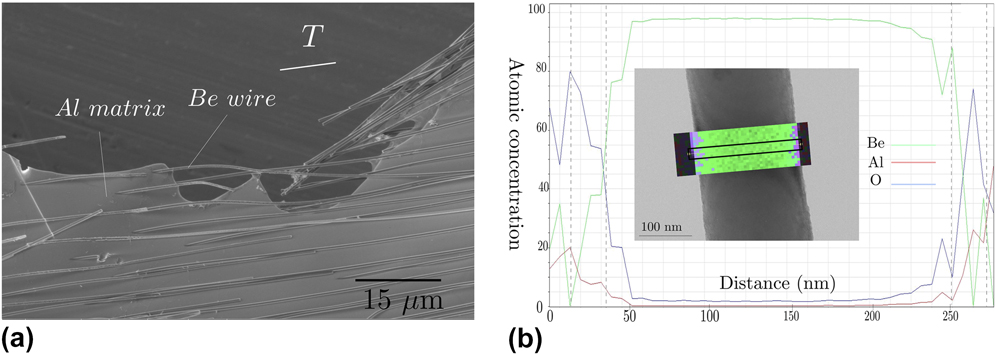
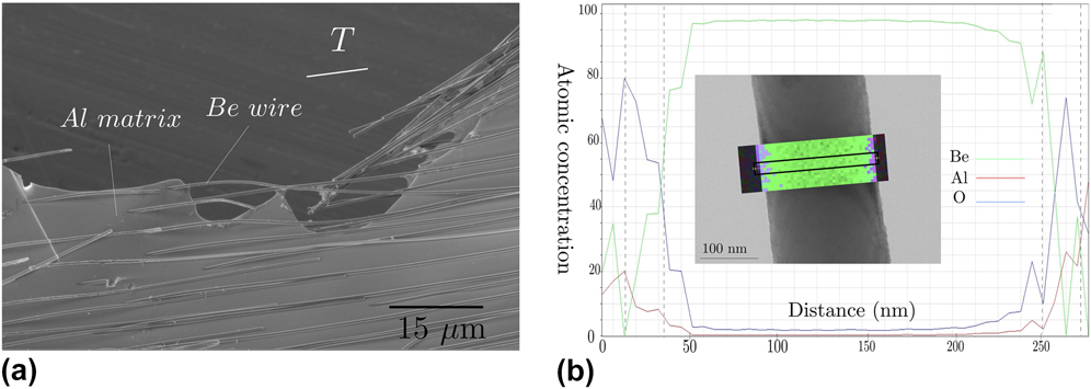
A directionally solidified Al–2.4 at.% Be eutectic alloy has been cut by electrodischarging machining parallel to the wire length. 3 by 1 mm samples were then mechanically polished and etched by a Struers A2 electrolytic solution at −10 °C. The fast etching of the aluminum matrix releases the Be wires in a circular etched region of 450 μm, corresponding to the diaphragm of the Struers electropolisher. The as-created TEM hole therefore contains several tens of wires of approximately the same diameter. Although bundles of superimposing wires are usually observed, isolated ones can be found principally in areas close to the TEM hole ridge [Fig. 1(a)]. Most of the wires have only one end attached to the rest of the matrix, but some are linked to both ends and can therefore be stretched. The wires were deformed by applying a uniaxial displacement on the sample glued on a copper grid. Reference Mompiou, Legros, Ensslen and Kraft18 In situ observations were performed on a JEOL2010 TEM (JEOL Ltd., Tokyo, Japan) operated at 200 kV. Video sequences were recorded on a hard drive/DVD writer using a MEGAVIEW III camera (Olympus Soft Imaging Solutions GmbH, Münster, Germany) at 22–25 fps. Chemical analysis of the wires was performed on a Philips CM20 FEG (Philips, Amsterdam, the Netherlands) operated at 200 kV and equipped with an Energy Dispersive Spectrometer SDD from Bruker (Bruker Corporation, Billerica, Massachusetts). Finally, the Finite Element Method was used to simulate stress distribution around a partially etched Be wire using the COMSOL Multiphysics software (COMSOL, Stockholm, Sweden).
(a) is a SEM image of a selectively etched Al/Be eutectic containing freestanding electron transparent Be wires surrounded by an Al matrix. (b) Atomic concentration of Be, Al and O elements along the line profile shown in the inset across a wire. The presence of an Al oxide at the wire surface is revealed.
III. RESULTS
Most of the wires in the hole are several tens of μm long. End-on observation of broken wires by SEM shows that the wires have a circular cross section [Fig. 1(a)]. The majority of the wires have a diameter of approximately 400 nm that is constant over the whole wire length, but wires with smaller diameters around 250 nm and some with a diameter constriction are also observed. Attached wires are usually straight and TEM observations reveal that most of them contain no dislocation. Wires that are detached at one end can be bent or cracked, and a high dislocation density is usually observed in the bent areas. Few
 $\left\{ {10\bar 12} \right\}$
twins can also be observed. Scanning Transmission Electron Microscopy Energy Dispersive Spectroscopy performed on an individual wire reveals the presence of a thin oxide layer, presumably Al2O3 [Fig. 1(b)] at the wire surface. This layer is supposed to arise from an incomplete etching of the Al matrix close to the wire that eventually oxidized during or after etching. As explained below, a small layer containing Al still remains close to the surface of the wires. A line scan across the wire [Fig. 1(b)] clearly indicates the presence of Al and O elements at the periphery of the Be wire (see the wire in the inset with the chemical map). The oxide layer that contains either some Al oxide (Al2O3) or a mixture of Al and oxide (Al/Al2O3) is thus estimated to be around 15–20 nm. Three deformation mechanisms that may or may not be influenced by this remaining thin oxide have been identified in these wires and are described below.
A. Fragile-like fracture
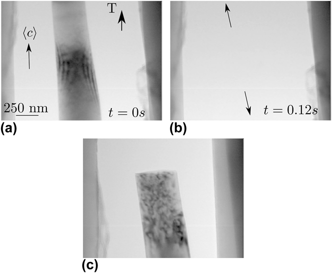
Figure 2 illustrates a typical fracture-like behavior that occurred during an in situ straining experiment. Upon straining, a 250 nm wire broke abruptly [Figs. 2(a)–2(b), and video 1 in the Supplementary Material). Because of the accumulated elastic strain during the loading, the wire sudden failure has led to the back motion of the two parts of the broken wire over a few microns [Fig. 2(c)]. This fracture is however not comparable to what is observed in ceramics or semiconductors at low temperature as one end of the wire in the crack area clearly shows a high density of defects not present prior to deformation. It is therefore likely that a localized plastic event (nucleation followed by rapid multiplication of dislocations) occurred in a small volume [a wire length of about 550 μm—lower end of the wire, Fig. 2(c)] leading to an abrupt failure of the wire. Such a nucleation and multiplication event is likely to be too fast to be captured at the video rate of the camera (25 fps). A similar phenomenon is also observed in defect free Al wires. Reference Mompiou, Legros, Sedlmayr, Gianola, Caillard and Kraft4
Abrupt fracture-like failure observed upon straining in a 250 nm diameter, dislocation free wire.

B. Twin migration
Smoother and more extended plastic deformation can however be observed associated to the migration of a
 $\left( {01\bar 12} \right)$
 $\left[ {01\bar 1\bar 1} \right]$
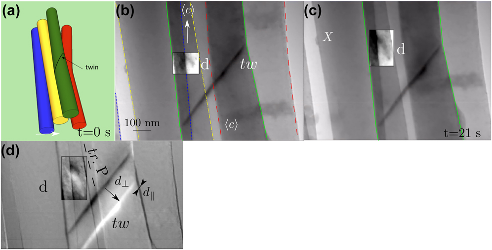
twin boundary as shown in Fig. 3. Twin migration over a distance of 4 μm has been observed after strain increments. The twin speed, reaching up to 12 nm/s, gradually decreases until the stress relaxed under a critical value below which the twin remained immobile.
Reference Mompiou and Legros19
In this case, several wires are grouped in a bundle, which produces several gray levels when the electron beam goes through superimposed wires. The sketch in Fig. 3(a) shows a possible stacking configuration of the 4 wires in which only the twinned one (green) is monitored during deformation. In the subsequent images, the wire of interest is delimited in green [and the others are delimited with dashed lined whose colors are related to Fig. 3(a)]. Figures 3(b) and 3(c) show two snapshots of the twin positions taken 21 s apart (for the corresponding video see the Supplementary Material). The twin motion appears continuous at a velocity of few nm/s. The migration distance d
⊥ can be clearly visualized by making an image subtraction (b) − (c) [Fig. 3(d)] with a fiducial marker X set as a fixed point. Then, an unchanged area appears uniformly gray, while the twin positions appear with white and dark contrasts. It can then be clearly seen that the twin migration has produced a displacement of the lower part of the wire of a distance d
‖ parallel to the twin plane. As a consequence, the wire is deformed by a shear strain also called coupling factor in the shear-coupling grain boundary migration scheme developed in Ref. Reference Cahn and Taylor20. Since the twin plane is inclined only 6° from the observation direction, the shear strain can be directly given by β = d
‖/d
⊥ ≈ 0.2. A detailed analysis of this coupling, reported in Ref. Reference Mompiou and Legros19, shows that the strain produced parallel to the wire axis is of the order of εp ≈ 0.3%. This plastic strain can be achieved by the repeated motion of twinning dislocations b
twin = (2 − λ)2/(2 + λ)2
 $\left[ {01\bar 1\bar 1} \right]$
with λ = (2/3)0.5
c/a (c and a being the lattice parameters).
Reference Serra, Bacon and Pond21
Interestingly, a moving dislocation (d) above the twin (tw) has been observed. An image difference [Fig. 3(c)] shows that the dislocation has moved in a plane (with a trace tr.P) almost parallel to the wire axis, and thus containing the 〈c〉 axis. Because the straining axis is also parallel to the wire axis, the resolved shear stress on this dislocation should be very small (the Schmid factor is about 0.1 here). The above observation seems to indicate that the wire surface, covered by an Al/Al2O3 layer, plays an important role in the deformation mechanism. In an Al/Al2Cu eutectic alloy deformed by creep and strained along the lamella axis, dislocations gliding in Al slip planes parallel to the lamella axis were similarly observed.
Reference Ignat, Bonnet, Caillard and Martin22
It was attributed to the inhomogeneous deformation between both phases. Similarly, dislocation glide parallel to the wire axis could also occur due to such strain inhomogeneities; it could even take place at the oxide/Be interface. This aspect will be discussed in Sec. V.
(a) Sketch of the wires bundle in which only the green one is monitored during the in situ tensile test. The wires are delineated with the same colors in (b). (b)–(c)
 $\left( {01\bar 12} \right)$
 $\left[ {01\bar 1\bar 1} \right]$
twin (tw) motion due to straining. (d) is the image difference (b) − (c). The migration normal to the twin plane (d
⊥) leads to a shear displacement parallel to the interface d
‖. Note the motion of dislocation d in a direction parallel to the wire axis.
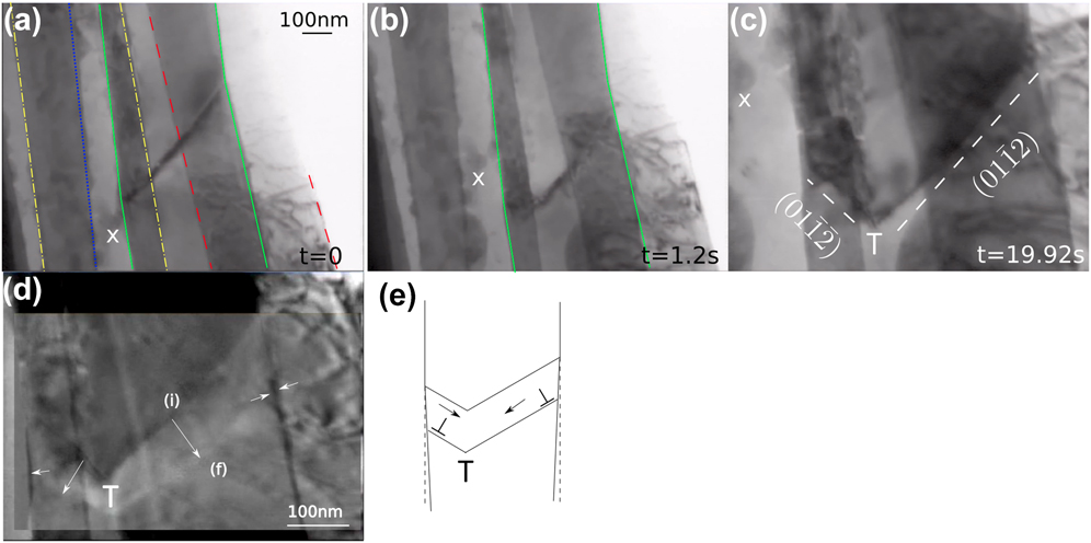
In the same wire bundle (the active wire is still delimited in green), Fig. 4 shows the initially flat twin interface along a
 $\left( {011\bar 2} \right)$
plane slowing down [Fig. 4(a)] and progressively forming a second facet along the
 $\left( {01 \bar 1\bar 2} \right)$
plane [Figs. 4(b) and 4(c)]. This can be interpreted by the blocking of the twin on the left hand side of the wire which shows a rough surface (Fig. 4) followed by the formation and migration of the second facet. The image difference shown in Fig. 4(d) and corresponding to a time interval of 38 s shows that the facets continue to move, but at a slower speed, around 1 or 2 nm/s. A similar offset on the wire sides indicated by arrows, can be explained by a shear in opposite directions along the two twin planes as sketched in Fig. 4(e). Although difficult to measure, the coupling factor is of the same order of magnitude than previous, which tends to indicate that the same twinning mechanism operates in both facets. This is in agreement with the fact that both facets are conjugate twinning planes.
Reference Christian and Mahajan23
However, because of the shear produced in opposite directions, strain incompatibilities are expected at the twin intersection T [Fig. 4(e)]. This strain is supposed to be released by dislocation emission until the twin stops. Identifying isolated dislocations is difficult, but rapidly changing contrast, typical of dislocation motions, can be evidenced by inspecting the video (see Supplementary Material).
(a–c) Blocking of the
 $\left( {01\bar 12} \right)$
twin followed by the development of the
 $\left( {01\bar 1\bar 2} \right)$
facet. X is a fixed point. (d) shows an image difference highlighting the motion of the facet from an initial position (i) in black contrast to a final position (f) in white contrast. The displacement at the wire side indicates the presence of an associated shear strain represented schematically in (e).
C. Dislocation plasticity
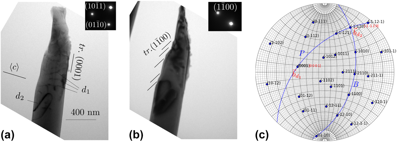
Plastic deformation by dislocation slip near fractured wires has been frequently observed postmortem. Figure 5 shows the fractured end of a wire under different diffraction conditions. It exhibits a ductile profile. The wire axis is here perpendicular to the 〈c〉 axis. Several shear bands along the prismatic
 $\left( {1\bar 100} \right)$
plane testify about an intense dislocation glide activity. In many cases, dense dislocation tangles involving 〈a〉 dislocations can be observed. In addition to these shear bands and tangles, two sets of dislocations more widely spaced than in the tangles could be studied in detail, namely dislocations (d1 and d2) (Fig. 5). From a contrast analysis in dark field mode using 6 different diffraction vectors, and shown in the Supplementary Material, the Burgers vectors are found to be
 ${{\bf{b}}_{{{\rm{d}}_1}}}{\rm{//}}\left\langle c \right\rangle$
and
 ${{\bf{b}}_{{{\rm{d}}_2}}}{\rm{//}}\left[ {11\bar 20} \right]$
, i.e., along the 〈a〉 direction. Additionally, the dislocation habit plane can be determined by using the apparent variation of the dislocation projected length as shown in the Supplementary Material. It was thus found that both d1 and d2 dislocations are located in the basal plane. Surprisingly, this result together with the determination of the Burgers vector indicates that dislocations d1 have a Burgers vector perpendicular to their habit plane, while the dislocations d2 have a Burgers vector in their habit plane. Whereas dislocations d1 are supposed to be sessile, dislocations d2 can glide in their basal plane. Their alignment forming a train of dislocations suggests that they have indeed moved. These dislocations belonging to a plane parallel to the wire axis show similarity with the moving dislocation d (Fig. 3). Although dislocations d2 are glissile, the resolved shear stress in their habit plane is supposed to be very small. Regarding dislocations d1, they can only move by climb, which appears unlikely in Be at room temperature. As for dislocations d1, the resolved shear stress acting on d2 dislocations is supposed to be very low so that climb should operate under osmotic forces.
Reference Mompiou and Caillard24
Despite their correlation to plastic deformation, the role of these dislocations in relaxing the applied stress is thus unclear at this point.
(a)–(b) Bright field images showing the fractured end of a wire. Steps along the wire indicate an intense dislocation slip along the prismatic plane
 $\left( {1\bar 100} \right)$
. Other dislocations noted d1 and d2 can be observed. (c) is the stereographic projection of the wire, showing the Burgers vectors, the basal (B) and the
 $\left( {1\bar 100} \right)$
prismatic planes.
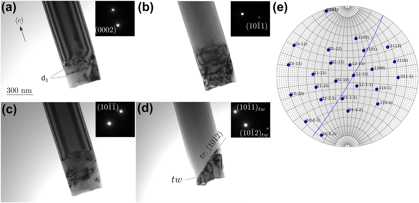
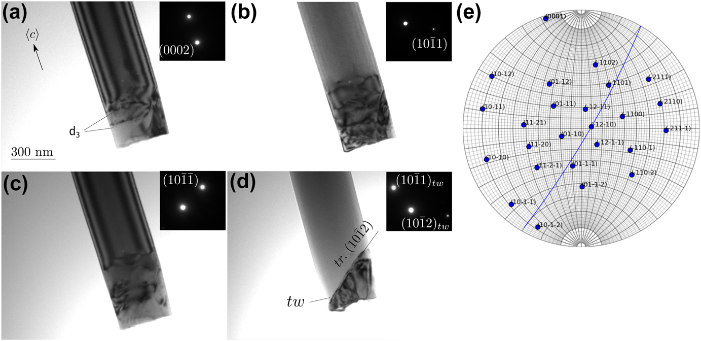
Wires oriented along their 〈c〉 axis are usually brittle but some plastic deformation can be noticed close to the fracture ends. Figure 6 shows a wire end under different diffraction conditions. As observed in Fig. 2, the fractured end appears abrupt and oriented 90° from the wire axis. Few dislocations noted (d3) can be observed near the end. This highly distorted area prevents a clear analysis of the contrast, but two interesting features can be noted. First, the visibility of some dislocations with a diffraction g = (0002) indicates that they are not 〈a〉 type, but presumably 〈c + a〉 or 〈c〉 [Fig. 6(a)]. Secondly a
 $\left\{ {10\bar 12} \right\}$
twin (tw) can also be observed. As shown in Fig. 3, the twin plane forms an angle of 49° with respect to the wire axis.
(a)–(d) Fractured end of a wire under different diffraction conditions (bright field images) showing dislocations (d3) and twin (tw). (e) is the corresponding stereographic projection where the twin plane is reported.
Plastic deformation in the observed wires, can be discussed through a Schmid factor analysis. For wires oriented along the 〈c〉 axis, their Schmid factors for twinning and pyramidal slip with either 〈c + a〉 or 〈a〉 dislocations present the highest values, ranging from 0.43 to 0.5, while both basal and prismatic slips exhibit low values, from 0.02 to 0.27. In the orientation where 〈c〉 is perpendicular to the wire axis, the Schmid factor for prismatic slip becomes important, ranging from 0.43 to 0.49, in the same range than pyramidal slip and twinning, while it is ranging between 0.15 and 0.32 for basal slip. This analysis emphasizes the following features: (i) for wires aligned along the 〈c〉 axis, the presence of a twin near a fractured end indicates that twinning is indeed the easiest deformation mode (Fig. 3); (ii) for wires whose axis is perpendicular to the 〈c〉 axis, deformation occurs by shear bands in prismatic plane and involves 〈a〉 dislocations (Fig. 5). In all cases, basal slip is not geometrically favored although it is the easiest slip system. Reference Beuers, Jonsson and Petzow16 In bulk samples, because the CRSS of basal slip is about 8 times smaller than for prismatic slip at room temperature, Reference Couret and Caillard17 slip systems with low Schmid factor can still be activated. This may explain the presence of 〈a〉 dislocation moving in the basal plane parallel to the wire axis (d2 in Fig. 5). Alternatively, the motion of these dislocations may have occurred at the Al/Be interface as discussed below. This could also be the case for dislocations d and d1. The marginal observation of non-〈a〉 dislocations indicates that other slip systems are more difficult to activate. To that respect, the plastic deformation of Be wires does not differ from Be bulk single crystals. Reference Beuers, Jonsson and Petzow16,Reference Couret and Caillard17
IV. DISLOCATION ANALYSIS AT THE Be/Al INTERFACE
Figure 7(a) shows dislocations d4 separated by about 60 nm in a region located about 4 μm below the moving twin (see Fig. 3), presumably close to the oxide layer. These dislocations are probably interfacial dislocations between the Be and a remaining Al layer below the oxide. To confirm this, we also observed Be wires in regions where the Al matrix was clearly present. Figure 7(b) shows the end of a wire surrounded by the Al matrix. The long axis of the wire corresponds to the 〈c〉 axis, the interface planes between Al and Be correspond to two prismatic planes (P
a and P
b). Basal (B) and second order pyramidal planes (π2a and π2b) can also be identified. The orientation relationships Be (1̄010)/Al (001) and Be
 $\left[ {1\bar 210} \right]$
/Al [010] are in agreement with previous studies.
Reference Van Aken and Fraser25,Reference Van Aken, Kim and Griffith26
In the twinned area these relationships become Be (0001)/Al (100) and Be
 $\left[ {1\bar 210} \right]$
/Al [010]. Interfacial dislocations, noted d5 in Fig. 7(b), can be observed in P
a. A contrast analysis based on the method described by Ref. Reference Marukawa and Matsubara27 was performed for a collection of two beam bright field images taken with 10 diffraction vectors g, to determine their Burgers vector. This analysis shown in the Supplementary Material shows that b is close to the [001] direction in Al and [1̄010] in Be. The Burgers vector is thus normal to the interface plane. Such defect can be produced by decomposition of a lattice dislocation originating from the Be or Al phase into interfacial dislocations. An example of such decomposition is shown on the dichromatic pattern [Fig. 7(c)]. The decomposition products relate lattice sites of each phase. They involve a glissile disconnection with a Burgers vector parallel to the interface and a sessile disconnection with a step character and a Burgers vector close to the normal to the interface, i.e., b close to [001] Al/
 $\left[ {10\bar 10} \right]$
Be. As in the twin area the [001] direction is supposed to be parallel to the [0001] direction in Be [see Fig. 7(c)], the dislocation d1 identified near the fracture tip in Fig. 5 may also be a dislocation located at the interface between Be and a thin layer of Al left. Its Burgers vector is therefore perpendicular to the plane containing the dislocation lines, which makes it a sessile dislocation. These sessile dislocations can only move by climb, and the fact that they are arranged as a pseudoperiodic array, close to an equilibrium configuration, render their motion even more difficult. Such an accommodation is feasible as discussed in Sec. V.
(a) Dislocations close to the wire surface 4 μm below the twin shown in Fig. 3. (b) End of a Be wire in the Al matrix. (c) Dichromatic pattern showing the decomposition of an Al lattice dislocation at the Be/Al interface. The projection axis is [100] Al//[0001] Be. The interface is underlined in black. The decomposition products consist of a disconnection whose Burgers vector is close to the normal to the interface plane and a glissile dislocation. (Be: Red, Al: Black, open dots correspond to Al lattice sites at z = 1/2).

Interfacial sessile dislocations may also play a role in initiating the nucleation either of perfect lattice dislocations or twinning dislocations in the Be wire. Moreover the observation of a train of dislocations in the basal plane d2 (Fig. 5), presumably also located at the interface, and moving parallel to the wire axis suggests that they may also play a role in the deformation process. To test this idea, we have performed FEM simulations of a wire surrounded by a thin Al oxide layer.
V. ANALYSIS OF THE STRESS DISTRIBUTION AT THE Al/Be INTERFACE
A. Model description
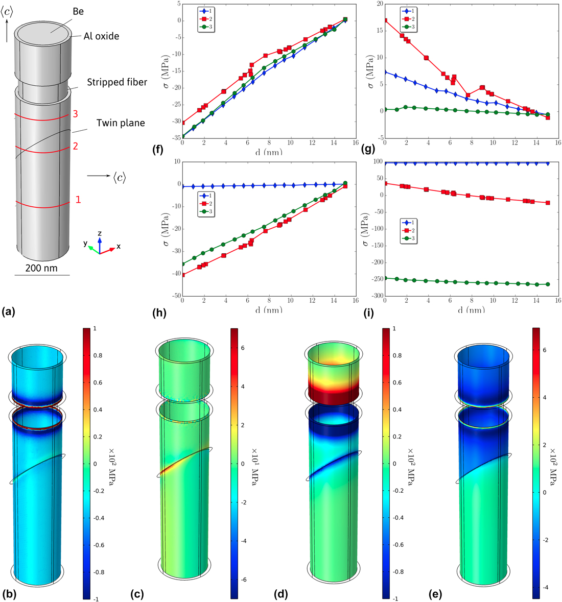
We consider the geometry of the wire containing a twin as shown in Fig. 3. The model is composed of a cylindrical wire of diameter d = 230 nm and height h
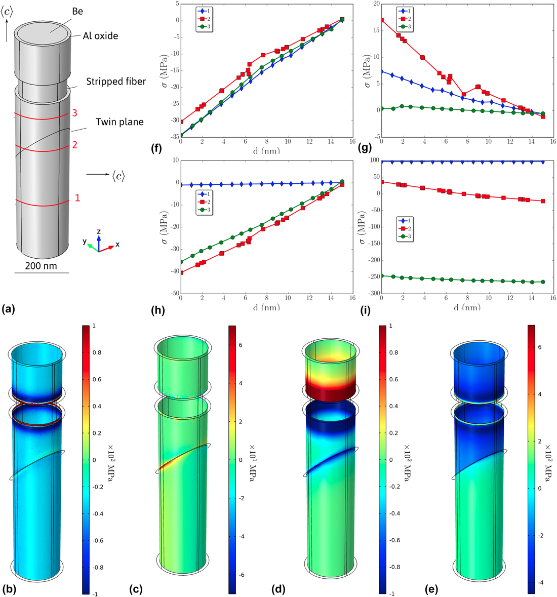
f = 1 μm of Be surrounded by a 15 nm thick alumina layer [Fig. 1(b)]. As a first approximation we considered that the eventual remaining Al layer can be neglected compared to the Al oxide [Fig. 8(a)]. To mimic the possible break of the oxide layer, either during the course of deformation or because of initial imperfections, we choose to remove the oxide along a small strip in the upper part [Fig. 8(a)]. The displacement of the position of the stripped area along the wire leads to similar results. To take into account the elastic anisotropy of the wire, the upper part of the crystal was oriented with the 〈c〉 axis parallel to the z direction with the corresponding Euler angles (φ1, Φ, φ2) = (−158.2, 2.7, −4.8), while the lower part was oriented according to (φ1, Φ, φ2) = (134.7, 86.2, 113.7). The Be elastic constants were taken as
Reference Smith and Arbogast28
(×1010 Pa): C
11 = 29.23, C
33 = 33.64, C
44 = 16.25, C
12 = 2.67, and C
13 = 1.4. The alumina layer is considered to be isotropic with ρ = 3900 kg/m3, E = 300 GPa and ν = 0.222. The top surface at z = h
f was displaced along the z direction by 0.005 h
f. The bottom surface was fixed along z while the point (0, 0, 0) along x, y and z directions, and the point (0, d/2, 0) along x and z directions. These conditions prevent the rotation and lateral displacement of the wire during straining. The displacement value was fixed to compare with the typical value of the yield stress, σYS ≈ 1.45 GPa ≈ 0.005 E
Be, measured from a micromechanical test on a single wire (Young’s modulus of the composite material Be plus oxide is given by the rule of mixture
 ${E_{\rm{f}}} = f{E_{{\rm{Be}}}} + \left( {1 - f} \right){E_{{\rm{A}}{{\rm{l}}_2}{{\rm{O}}_3}}}$
, with f being the volume fraction of the wire. Since f ≈ 0.02, then E
f ≈ E
Be). FEM calculations were performed using the COMSOL software.
(a) Description of the model. Radial (b), tangential (c) and longitudinal (d) stress at the interface between the wire and the oxide. (f) to (h) are respectively, radial, tangential and longitudinal stress profiles along the x direction at three different heights [noted 1, 2, 3 in (a)] in the oxide layer (the origin corresponds to the interface location). (e) and (i) correspond to σrz (see text for details).
B. Results
We were interested in looking at the deformation produced along the cylinder, to understand why dislocations were observed to move parallel to the z direction, while their Schmid factor being zero. Our initial hypothesis being that of an isotropic cylinder strained uniaxially, we wanted to test more precisely what are the intrinsic Be anisotropy contributions to the strain. To estimate the strain along the wire, we first removed the strain that can be accommodated by slip and twinning in Be, i.e., the strain εa = 0.005h f/h f = 0.005. The residual strain tensor is then as follows:
 $${\overline{\overline \varepsilon } _{\rm{r}}} = \overline{\overline \varepsilon } - \left( {\matrix{ 0 0 0 \cr 0 0 0 \cr 0 0 {{\varepsilon _{\rm{a}}}} \cr} } \right) = \left( {\matrix{ {{\varepsilon _{xx}}} {{\varepsilon _{xy}}} {{\varepsilon _{xz}}} \cr {{\varepsilon _{xy}}} {{\varepsilon _{yy}}} {{\varepsilon _{yz}}} \cr {{\varepsilon _{xz}}} {{\varepsilon _{yz}}} {{\varepsilon _{zz}} - {\varepsilon _{\rm{a}}}} \cr}} \right) \quad .$$
We then looked at the components of the strain in the plane along the wire, i.e., in the cylinder with a normal n = 1/(x 2 + y 2)0.5(x, y, 0). Considering that the deformation is accommodated by dislocations in the direction of their Burgers vector b. The residual stress is as follows:
 $${\sigma _{\rm{r}}} = \left( {\overline{\overline C} \,{{\overline{\overline \varepsilon } }_{\rm{r}}} \cdot \vec n} \right) \cdot \vec b$$
with C being the stiffness tensor. The stress can be decomposed into radial [b = 1/(x 2 + y 2)0.5 (x, y, 0)] (σrr), tangential [b = 1/(x 2 + y 2)0.5 (y, −x, 0)] (σrt) and longitudinal [b = (0, 0, 1)] (σrl) components.
The σrr, σrt and σrl components are shown at the interface between Be and the oxide in Figs. 8(b)–8(d) and along the x direction [Figs. 8(f)–8(h)] in the oxide layer at 3 different positions along the wires noted 1, 2 and 3 in Fig. 8(a). While radial and longitudinal components exhibit values larger than few tens of MPa especially at the border of the stripped area, the tangential component is one order of magnitude smaller. At the two borders between the oxide layer and the stripped wire, radial and longitudinal components reach values of the order of 1 GPa [the color scales in Fig. 8(b) and 8(d) have been adjusted between −100 and 100 MPa to highlight stress differences]. Stress profiles in the oxide layer show that the compressive stress decreases and tend to zero at the wire surface for both radial [Fig. 8(f)] and longitudinal [Fig. 8(h)] components. An opposite behavior is found for the tangential component [Fig. 8(g)]. In contrast to the longitudinal component that is substantial only near the twin plane and close to the stripped area, the radial component reaches high values homogeneously along the whole wire. This can be qualitatively explained by the large difference of the Poisson ratio between Be (νBe = 0.032) and Al oxide (νoxide = 0.222). In first approximation, this difference generates a compressive strain εrr ≈ (ν oxide − νBe)εa ≈ 10−3. The corresponding stress values obtained are expected to be sufficient to activate dislocation motion at the interface, especially if the oxide layer is locally fractured. The direction of the motion is determined by the force direction, i.e., according to the Peach–Koehler equation:
 $$\left( {{{\overline{\overline \sigma } }_{\rm{r}}} \cdot \vec b} \right) \times \vec u = \vec F\quad ,$$
where u = 1/(x 2 + y 2)0.5 (y, −x, 0) is the line direction taken tangent to the cylinder. If we consider a Burgers vector b perpendicular to the interface, i.e., b = b/(x 2 + y 2)0.5 (x, y, 0), the components of the force in the radial, tangent and longitudinal directions are F r = bσrl, F t = 0 and F l = −bσrr, respectively. The component of this force is important along the z direction everywhere along the wire as indicated by the σrr value, and corresponds to a climb force. The glide component is also significant but principally close to the stripped area. However, this force leads to the motion of the dislocation out of the interface in the oxide or Al left layer. If we now consider a Burgers vector b parallel to the interface, i.e., b = b (0, 0, 1), this yields to the radial, tangent and longitudinal components equal to F r = bσrz , F t = 0 and F l = −bσrl respectively, where σrz = C 13 (ε xx + ε yy ) + C 33 (ε zz − εa). In this case, the glide component mainly stands along the z direction, and has also a strong value, especially close to the stripped area. The climb component is radial here and forces the dislocations out of the wire. The stress component σrz shown in Fig. 8(e), indeed exhibits large compression and tension values. The corresponding stress profile shown in Fig. 8(i) indicates a strong compressive stress (≈250 MPa) above the twin plane and tensile stress (≈100 MPa) below, both almost constant in the oxide layer. These stresses arise because the wire below the twin plane is comparatively softer than the upper part, and deforms more than the upper part for an overall fixed imposed deformation.
In conclusion, we have shown that dislocations with a Burgers vector parallel to the wire (similar to d2 in Fig. 5) or normal to the Al/Be interface (similar to d1 in Fig. 5) can take part in plastic relaxation. It is shown that they would nucleate preferentially close to the area where the outer Al oxide is cracked, and where stress concentration arises. This might explain why dislocations d1 and d2 were observed close to the fractured area despite having a Schmid factor deduced from the applied longitudinal stress, i.e., close to zero. Because of this remaining oxide, both dislocations experience glide and climb components that are on the order of several tens of MPa. d2-type dislocations can move by glide along the wire, while d1-type dislocations are expected to climb along the wire. This latter motion is probably difficult at room temperature due to the necessity of the diffusion process. However, this process cannot be completely ruled out due to (i) a possible easier vacancies/interstitial diffusion along the interface, and (ii) the high stress concentration, especially near the stripped area.
VI. SUMMARY AND CONCLUSIONS
Plastic deformation of submicron Be wires has been investigated by in situ TEM straining experiments. Because Be wires were extracted by electrochemical etching from an eutectic alloy, they stood free of implantation defects such as the ones observed during standard FIB preparation. We showed that the wire deformation behavior is strongly dependent on their orientation due to the strong anisotropy of the hcp structure of Be. To that respect, Be wires tend to behave most similarly to Mg pillars. Reference Byer and Ramesh11 In dislocation free wires, abrupt fragile-like fracture is recorded presumably associated to a dislocation avalanche triggered at high yield stress. Indeed individual wires tested in SEM show a remarkable high yield stress around 2 GPa. Reference Mompiou, Legros, Ensslen and Kraft18 This fragile-like behavior is reinforced by the 〈c〉 axis orientation of the wire that is unfavorable for the easy prismatic and basal dislocation glide. On the contrary, the twinned area can plastically deform by prismatic slip because its 〈c〉 axis is almost perpendicular to the wire axis. Twin migration was also observed. This mechanism contributes both to the expansion of the twinned region and to the total plastic deformation. Shear bands along prismatic planes have indeed been observed in twinned regions. Overall, these observations do not reveal abnormal dislocation behavior compared to bulk samples.
However, because most of the wires are initially dislocation free, twins or dislocations have to be nucleated directly from the wire surface and more probably at the Be/Al interface. The role of the interface is revealed by the unusual observation of dislocations with Burgers vectors parallel and perpendicular to the wire axis and lying in planes parallel to the wire. Further investigations indicate that these dislocations are probably dislocations left at the interface between Be and a remaining Al layer, left from the Al matrix of the eutectic alloy, and partially oxidized. FEM analysis of the stress distribution when a composite Be/Al oxide wire is strained uniaxially show that dislocations with both radial and longitudinal Burgers vector participate to strain accommodation. High stress levels can even be reached in the area where the oxide layer is fractured. Contrary to the bulk material, plastic deformation is thus largely dependent on twin/dislocation nucleation processes in the outer shell at the wire surface. The existence of such a shell is hardly inevitable in most metals because of oxidation. As a side effect, the existence of the outer shell may contribute to the blocking of dislocations from emerging at free surfaces, thus leading to strain hardening. This was revealed during the operation of spiral sources in Al naturally oxidized Reference Mompiou, Legros, Sedlmayr, Gianola, Caillard and Kraft4 or in purposely coated metallic wires. Reference Ng and Ngan29,Reference Lee, Jennings and Greer30 Recent dislocation dynamics simulations performed on various coated pillars deformed in compression tend to confirm the hardening role of the outer shell while preserving the size effect on the yield stress. Reference El-Awady, Rao, Woodward, Dimiduk and Uchic31 Unusual plastic accommodation in thin metallic films on substrate has also been evidenced during thermal cycling in Cu. Dislocation glide parallel to the interface has been observed in response to a tensile deformation parallel to the interface. This was interpreted by strain redistribution due to surface and grain boundary diffusion. Reference Balk, Dehm and Artz32 In conclusion, it appears that modeling pillar or wire mechanical properties would require in the future appropriate descriptions of what was considered in most earlier works as a free surface. This has also been emphasized recently for Pd wires. Reference Chen, He, Shin, Richter and Gianola33 The importance of diffusional processes occurring preferentially at the interface is thought not only to impact strain accommodation but also probably dislocation/twin nucleation processes. The noncontinuity and heterogeneity of the outer shell, which can arise from the plastic deformation itself, leading to stress concentration, is also a crucial parameter.
Supplementary Material
To view supplementary material for this article, please visit https://doi.org/10.1557/jmr.2017.327.
ACKNOWLEDGMENTS
The authors would like to thank L. Durand for her assistance in running FEM simulations and D. Lamirault for the sample preparation. This work has been supported by the French National Research Agency under the “Investissement d’Avenir” program reference No. ANR-10-EQPX-38-01.