Introduction
To fulfill the requirement of small-sized antenna for modern wireless communication, the microstrip antenna with a metallic patch fabricated on a dielectric substrate with ground plane either on the opposite side or same side [Reference Balanis1] can be used. These antennas are low profile, simple, cost-effective, and conformable to planar as well as non-planar surfaces [Reference Balanis2]. The flexibility, as well as the versatility of the antenna structures, can be further increased by using different feeding techniques [Reference Garg, Bhartia, Bahl and Ittipiboon3]. Incorporation of fractal geometries further makes their size compact [Reference Kumar and Singh4, Reference Singh and Singh5]. The space-filling property of the fractals results into a compact size. The self-similarity property further facilitates these antennas to have multiband as well as wideband characteristics [Reference Zarrabi, Mansauri, Gandji and Kuhestani6, Reference Werner, Haupat and Werner7]. The performance parameters of these antennas further can be improved by inserting slots in the ground plane [Reference Roy, Bhattacharya, Chowdhury and Bhattacharjee8]. Soft computing methods can be applied to improve the performance parameters of the antenna [Reference Chamaani and Mirtaheri9, Reference Kumar and Singh10]. Cognitive radio is an aware and adaptive radio with the reconfigurable front end [Reference Polson11]. These systems endlessly sense the spectrum and communicate within the free band. A wideband antenna with omnidirectional radiation pattern is necessary for spectrum sensing [Reference Siva Sundara Pandian and Suriyakala12] in cognitive radios. In [Reference Gomez-Nunez, Jardon-Aguilar, Tirado-Mendez and Flores-Leal13] a slotted disc UWB antenna for spectrum sensing is presented for a frequency range of 0.7–11.23 GHz with large size of 150 × 120 mm2 with quasi-omnidirectional radiation pattern. In [Reference Siva Sundara Pandian and Suriyakala14] Sierpinski triangular fractal geometry is presented leading to the simulation covering 8–12, 12–18 and 18–26.5 GHz bands for spectrum sensing in cognitive radio but with simulated results only. In [Reference Narayan, Caradec, Ataman and Manthian15] a UWB antenna is proposed for the frequency range of 1.35-more than 30 GHz but with non-omnidirectionality in radiation pattern and with simulated results only. In [Reference Nayak, Verma and Kumar16] an E-shaped fractal antenna is designed for spectrum sensing in cognitive radios with a multiband response in 0.9–4 GHz frequency range, but only simulated results are provided. In [Reference Nachouane, Najid, Taribak and Riouch17] integrated sensing and communicating antenna is proposed for cognitive radios in which sensing antenna is having a bandwidth from 2 to 5.5 GHz with dimensions of 80 × 65 mm2, the radiation pattern is quasi-omnidirectional. In [Reference Sharma and Tripathi18] a frequency reconfigurable integrated antenna for cognitive radio application is presented for the frequency range of 2–12 GHz with a size of 60 × 60 mm2. In [Reference Siva Sundara Pandian and Suriyakala19] a microstrip modified Koch fractal antenna for cognitive radio applications is presented with four resonant frequencies 3.2, 5.2, 6, and 9.5 GHz which is having small size as compared to proposed geometry but with narrow bandwidth. Keeping in mind the requirement of spectrum sensing antenna and limitations of small bandwidth with large size and non-omnidirectionality of literature available, a modified shape of the Koch curve antenna is designed with wideband characteristics in three bands with omnidirectional radiation pattern. Furthermore, the ground plane is miniaturized by inserting a slot in the ground plane and Moth flame optimization (MFO) [Reference Mirjalili20] is applied to optimize the ground plane.
Proposed fractal antenna design
Antenna design
Geometrical details of the proposed modified Koch curve antenna are presented in Fig. 1. The generator is a long wire of width (W) 80 mm and strip width (t) 1 mm. In the first iteration, the generator is divided into four equal parts and a trapezoidal is made with indentation angle θ = 60° on central two parts. Then a Koch curve technique is applied with indentation angle 60° on top of the trapezoidal. In the second iteration, the same shape is repeated on every segment of the first iteration. Microstrip feed with a width of 2 mm and length 19 mm is used. FR4 material with dielectric constant ε r = 4.4, the height of substrate h = 1.6 mm and loss tangent δ = 0.02 is used for the design of the antenna. The copper cladding of 35 μm, over the substrate, is used for fabrication.
Geometrical description of the proposed design: (a) generator, (b) first iteration, (c) second iteration.

The proposed modified Koch fractal antenna is generated using iterated function system (IFS) with the help of a set of affine transformations having θ = 60° shown by Table 1. Fractal geometry is obtained by repeatedly applying affine transformation W 1, W 2, W 3, …, W 8 given by equation (1)

IFS generator equations for proposed geometry.

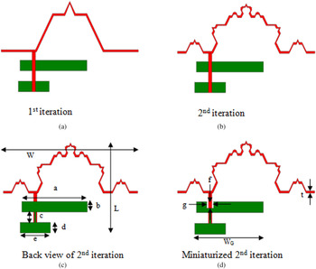
In Fig. 2, various iterations of the proposed design are presented and its dimensional parameters are given in Table 2. In Fig. 2(d), a 3 × 4 mm2 slot is inserted in the ground plane to get miniaturized shape.
Iterations of the proposed design: (a) first iteration, (b) second iteration, (c) back view of the second iteration, (d) miniaturized second iteration.

Dimensional parameters of the antenna

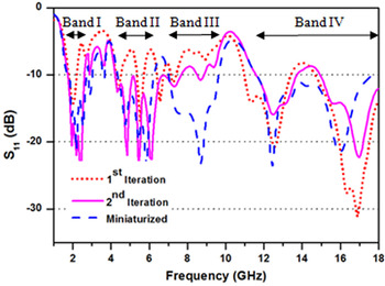
MoM-based IE3D software is used for designing the geometry. IE3D is a full-wave electromagnetic and optimization package. Figure 3 shows the S 11 parameters of the antenna for various iterations. It has been observed from the graph that impedance matching improves in the second iteration in Bands I and II. In the first iteration lower cut off frequency is 1.854 GHz and in the second iteration, it is shifted to 1.769 GHz. In miniaturized shape, it is again at 1.854 GHz but with very good impedance matching in Bands III and IV. There is an existence of four bands after miniaturization as shown in Fig. 3.
S 11 of modified Koch curve with various iterations.

Optimization of proposed fractal antenna
MFO is applied on the width of the ground plane of the proposed design. It is inspired by the navigation method of moths in nature called transverse orientation. The objective function for MFO is computed using polynomial curve fitting method in MATLAB environment as described in equation (2). The main aim is to find the value of ground width “a” of Fig. 2(c), to attain reflection coefficient f(z) below −10 dB for frequencies lies between Bands II and III.
Objective function = min f(z)
where

and y = (x – 10.182)/3.6, x is the variable used for different values of ground width “a”.
Table 3 depicts the optimized value of width “a” and corresponding geometry is shown in Fig. 4. After optimization, Band I gets broader to 1.683–3.05 GHz. Band II (4.417–6.211 GHz) and Band III (7.065–9.543 GHz) got merged into the single band (4.246–9.714 GHz), which clearly shows merging of both bands as well as the extension of both lower and upper cutoff frequencies. Frequency range of Band IV i.e. (11.68–17.57 GHz) becomes (11.25–18 GHz) with optimization as shown in Fig. 5.
Optimized geometry of the proposed design.

S 11 after optimization.

Dimension obtained after optimization

Fabrication of the proposed fractal antenna
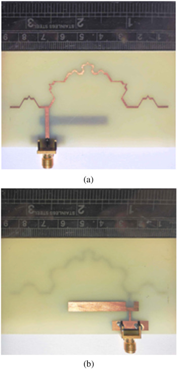
The proposed design using modified Koch curve fractal geometry is validated after obtaining the optimized results and fabricating the antenna in the form of a patch on a double-sided FR4 copper clad board using printed circuit technology as shown in Fig. 6. A 50 Ω SubMiniature version A (SMA) edge mount female connector is used with microstrip feed and ground plane to achieve experimental observations.
Fabricated antenna: (a) front view, (b) back view.

Results and discussion
Simulated and measured S 11
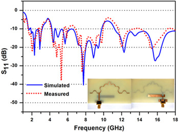
Experimental validation of the proposed fractal antenna is carried out by having a comparison of simulated and measured S 11 from the fabricated antenna. Vector network analyzer was used for making measurements on the fabricated antenna. The simulated and measured results are compared for concluding its actual performance. The value of the corresponding S 11 is measured at different frequencies of its operation in the specified bands. The graph obtained in Fig. 7 reveals that there is a good similarity in the simulated and measured outcome pertaining to the proposed bands at low frequencies. A slight deviation in measured S 11 is observed which is due to lot of factors like fabrication tolerances as well as experimental errors during real-time measurements.
Simulated and measured S 11 of the proposed design.

Gain versus frequency
Figure 8 depicts the simulated and measured gain of the proposed design at various frequencies of the proposed band. The antenna is kept at a distance of 2 m from reference antenna (Horn antenna). The simulated value of gain is 2.08, 2.24, 1.29, and 5.27 dBi and a measured value of the gain is 1.067, 1.304, 1.102, and 4.181 dBi at 2.2, 7.75, 12.28, and 15.78 GHz, respectively.
Simulated and measured gain of the proposed design.

Radiation pattern
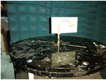
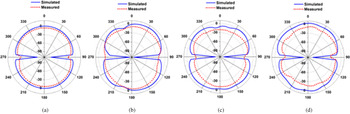
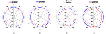
Figure 9 presents the fabricated antenna mounted in an anechoic chamber in front of the reference antenna for real-time measurements. Figures 10 and 11 indicate the simulated and measured radiation pattern of the proposed fractal antenna in elevation and azimuth planes, respectively, after having the optimization of the proposed geometry. The radiation pattern is directional in elevation plane and non-directional in the azimuth plane, which confirms to the fact that the radiation pattern is omnidirectional, which of course is the fundamental requirement of the spectrum sensing antenna in cognitive radio applications. A small variation is observed at high frequency in E-plane and H-plane. Apart from that, there is good matching in the simulated and measured results which further proves the validity of the proposed design.
Fabricated antenna in anechoic chamber.

Normalized polar plots for E-plane at (a) 2.2 GHz, (b) 7.75 GHz, (c) 12.28 GHz, (d) 15.78 GHz.

Normalized polar plots for H-plane at (a) 2.2 GHz, (b) 7.75 GHz, (c) 12.28 GHz, (d) 15.78 GHz.

Table 4 presents the comparison of antenna available in the literature with the proposed antenna and it has been observed that proposed antenna is having smaller dimensions and broad bandwidth as compared to many other available fractal antennas of comparable size. In the literature most of the antennas are narrowband but the proposed shape is broadband. Copper required for the proposed shape is also very less.
Comparison of the proposed antenna with other fractal antennas in literature

Conclusion
A modified Koch curve patch antenna has been developed for spectrum sensing in cognitive radio having the operation in three bands 1.683–3.05 GHz (57.7%), 4.246–9.714 GHz (78.33%), 11.25–18 GHz (46.15%) with broadband characteristics and omnidirectional radiation pattern. Comparison of simulated results with the measured results is done to validate the performance of the proposed design. The antenna is fabricated with 1.6 mm thick FR4 substrate (ε r = 4.4 and δ = 0.02). The presented approach has a potential future in the development of spectrum sensing patch antennas for cognitive radio applications in other bands as well.
Acknowledgements
The authors are grateful to Prof. (Dr.) Shailendra Jain, Director, Sant Longowal Institute of Engineering & Technology (SLIET), Longowal-148106, District Sangrur, Punjab, India for his continuous support and encouragement during the present work. They also acknowledge the excellent technical support extended by the Department of Electronics and Communication Engineering, SLIET, Longowal as well as IIT Delhi to complete experimental work on Vector Network Analyzer and Anechoic Chamber.
 Monika Aggarwal received her B.Tech and M.Tech in Electronics & Communication Engineering from Punjab Technical University, Jalandhar. She is currently pursuing Ph.D. in fractal antennas for cognitive radio from SLIET, Longowal. Since 2000, she had taught many courses like Digital signal processing, VLSI design, Microwave and Radar. She had published more than 30 papers in various International journals/conferences and national conferences.
 Amar Partap Singh Pharwaha received his B.Tech in ECE from GNDU, Amritsar in1990. He had done his M.Tech degree from REC, Kurukshetra in 1994 and Ph.D. degree in 2005. At present, he is a professor of ECE at SLIET, Longowal. Dr. Singh is credited with a professional experience of more than 25 years. He has guided seven Ph.D. theses and six more students are pursuing their Ph.D. degrees under his supervision. He has published more than 180 research papers in various national and international journals/conferences and received various awards including IETE Students Journal Award-2006 by IETE, New Delhi, Certificate of Merit in 2006, KF Antia Award in 2009, Sir Thomas Award for the year 2010, and again KF Antia Award in 2014 by the Institution of Engineers (India).