I. INTRODUCTION
Inconel 740, a relatively new member of Ni-based superalloy family, has been developed for applications to advanced ultra-supercritical steam boiler tubing in fossil power plants.Reference Zhao, Xie, Smith and Patel1, Reference Evans, Maziasz, Swindeman and Smith2 As the target steam condition of the new boiler was 375 bar and 700 °C, this alloy was designed to have excellent performances at 700–750 °C; i.e., good microstructure stability, high resistance to coal ash corrosion and oxidation, and high creep-rupture strength (for 100,000 h rupture life at 100 MPa and for component life longer than 20 years).Reference Zhao, Xie, Smith and Patel1, Reference Evans, Maziasz, Swindeman and Smith2 Like many other Ni-based superalloys, this Inconel 740 is primarily strengthened by the precipitation of very fine gamma prime (γ′) (having an ordered L12 structure) in the disordered gamma (γ) matrix.Reference Zhao, Xie, Smith and Patel1, Reference Evans, Maziasz, Swindeman and Smith2 Thus, the mechanical properties of the alloy are strongly dependent on the size and fraction of the γ′ precipitates.
It is generally accepted that the precipitation strengthening in Ni-based superalloys is mainly controlled by cutting mechanism rather than bowing (or typically referred to as Orowan) mechanismReference King3, Reference Reppich, Schepp and Wehner4: Although a pair of a/2 {111} dislocations passes through the γ/γ′ structure, the first dislocation enters the spherical γ′ precipitates with the formation of an anti-phase boundary (APB) and the following dislocation removes it.Reference Gopalan, Rajaaman, Viswanathan, Gopinathan and Venkadesan5–Reference Nembach8 This type of cutting mechanism can be roughly subdivided into two groups; weakly coupled dislocations (WCD or weak pair coupling) modelReference Brown, Ham, Kelly and Nicholson9 and strongly coupled dislocations (SCD or strong pair coupling) model.Reference Huther and Reppich10 In superalloys, the former is typically applied to the case where the size and volume fraction of γ′ are small,Reference Brown, Ham, Kelly and Nicholson9 whereas the latter is known to be more appropriate for the case where the spacing of the dislocation pairs becomes comparable to the particle diameter.Reference Huther and Reppich10
Although many studies have been performed to observe the variations in microstructures and mechanical properties in the thermally aged or crept superalloy specimens, little efforts have been made on the influence of thermo-mechanical treatment at high stress and high temperature. Especially, to our best knowledge, no research on the issue has been conducted for Inconel 740. With this in mind, how the mechanical properties of the Inconel 740 can be affected by the thermo-mechanical treatment was investigated in this study. The results provided important clues for the precipitation behavior and the way in which it may contribute to the strengthening of the material.
II. EXPERIMENTAL DETAIL
The material examined in this study is a commercial grade Inconel 740 (produced at Special Metals Corporation) whose nominal chemical composition (wt%) is 0.03C–25Cr–0.5Mo–20Co–0.9Al–1.8Ti–2Nb–0.3Mn–0.7Fe–0.5Si and (balance) Ni. Ingots of the alloy were homogenized at 1204 °C for 16 h and hot worked at temperature above 1050 °C for 30 min. and then water-quenched. The standard precipitation treatment was made at 800 °C for 16 h and then air-cooled.Reference Zhao, Xie, Smith and Patel1 In the commercial-grade standard sample, the average size of grains and γ′ precipitates are known to be about 50 μm and 40 nm, respectively.Reference Zhao, Xie, Smith and Patel1
Thermo-mechanical treatment was carried out using a thermo-mechanical cycling equipment Gleeble 1500 (Dynamic Systems Inc., Poestenkill, NY). The rectangular cuboid sample (5 mm × 6 mm × 12 mm) was heated up to 700 °C at a heating rate of 70 °C/s in an argon environment and then held at the peak temperature for 1 h under different levels of compressive stress: σ = 0, 300, and 800 MPa. Since the yield strength of the alloy is 648 MPa at 700 °C, 300 and 800 MPa are stresses in the “elastic” and “plastic” regime, respectively. After the thermo-mechanical treatment, the sample was quenched in air.
Microstructure was examined by using field emission scanning electron microscopy (JSM-6340F; JEOL Ltd., Tokyo, Japan). With the scanning electron microscopy (SEM) micrographs, the size and fraction of γ′ were quantitatively measured using an image analyzer software (Image-pro; Media Cybernetics Inc., Bethesda, MD). An electrical etching (at 10 V for 90 s in a solution of 10 mL perchloric acid, 30 mL propionic acid, and 40 mL ethanol) and a chemical etching (for 10 s in a solution of 33 mL nitric acid and 66 mL hydrochloric acid) were adopted for measuring the size and fraction of γ′, respectively. Adoption of different methods was because the electrical etching (that selectively etches out the γ matrix having a large fraction) could induce an overestimation of γ′ fraction, whereas the chemical etching (that selectively etches out the γ matrix) could result in an overestimation of γ′ size.
To investigate the mechanical properties, nanoindentation experiments were carried out using a Nanoindenter-XP (MTS System Corp., Oak Ridge, TN) with a common Berkovich indenter. During the test, the sample was loaded up to the peak load (P max) of 10 mN under a constant strain rate of 0.05 s−1. The tip calibration and the hardness calculation were conducted in accordance with the Oliver–Pharr method.Reference Oliver and Pharr11 More than 10 indentation tests under each testing condition were made on electropolished samples instead of mechanically polished samples to avoid artifacts related to a hardened surface layer. The specimen surfaces were initially ground with fine SiC paper of no. 2000 and then electrically polished at 40 V for 20 s in a solution of 850 mL methanol and 150 mL hydrochloric acid at a room temperature.
III. RESULTS AND DISCUSSION
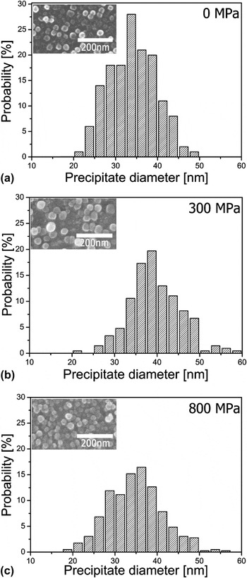
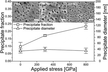
Representative SEM micrographs for the thermally treated only (i.e., σ = 0 MPa), the elastically stressed (300 MPa), and the plastically stressed (800 MPa) samples etched “electrically,” and the measured size distribution of γ′ precipitates are shown in Fig. 1. All samples exhibited very fine dispersion of spherical γ′ precipitates in γ matrix. Using high resolution SEM images (×70,000), the size and fraction of γ′ were investigated, with the results summarized in Fig. 2 (in which the SEM micrographs of the “chemically” etched samples are also provided). At least six high resolution micrographs were used for measuring the γ′ fraction and more than 150 precipitates were examined for estimating the diameter of the spherical precipitates. In the figure, with increasing applied stress, the fraction of γ′ continuously increased, whereas their diameter was not significantly changed and remained in the range of 20–60 nm (also see Fig. 1). As the γ′ size is almost unchanged in the highly stressed sample, one might imagine that the increase in γ′ fraction with the stress is mainly attributed to the enhanced nucleation of the γ′ precipitates rather than their growth. Note that the time for the thermal–mechanical treatment (i.e., 1 h) is conceivably too short to induce proper precipitate coarsening.
Size distribution of γ′ precipitates: (a) 0 MPa, (b) 300 MPa, and (c) 800 MPa. Inset images are examples of the SEM micrographs used for measuring the size of γ′.

Plot of γ′ fraction and size with the stress applied at 700 °C. Inset images are examples of the SEM images used for measuring the fraction of γ′.

The possible enhancement of γ′ nucleation due to the external stress might be explained by taking into consideration the nucleation rate of a γ′ precipitate and its Gibbs free energy barrier.Reference Porter and Eastering12 If the concentration of heterogeneous nucleation sites is C 1 per unit volume, the heterogeneous nucleation rate can be simply given as

where k and T are Boltzmann’s constant and absolute temperature, respectively, f is a complex factor depending on how frequently a critical nucleus can receive an atom from the matrix, and ΔG is critical value of Gibbs free energy barrier for the nucleation that can be obtained from the classical theory of nucleation as

where V and A are the volume and surface area of precipitate, respectively, γ is the inter-phase interface energy, ΔG v is the change in volume free energy, ΔG s is the change in misfit strain energy, and ΔG d is the amount of free energy that can be released by heterogeneous nucleation on crystalline defects (e.g., dislocations in the present work).
The external stress strains the material elastically or plastically, depending on the level of stress. In the case that the stresses do not surpass the yield stress, the resulting elastic strains may partially accommodate the misfit strain of (fully or partially) coherent precipitates, which results in the reduction of misfit strain energy term ΔG s and thus the total free energy barrier (ΔG) in Eq. (2).Reference Sauthoff13 It is noteworthy that, although the portion of ΔG s in ΔG can be small, the nucleation rate can be significantly enhanced by the change in ΔG s because of the exponential dependence of the rate on the activation energy. Therefore, the elastic stress will certainly lead to the easier nucleation of γ′ precipitates and thus increase in their fraction.
Much higher fraction of γ′ precipitates in the plastically stressed sample might be associated with both increasing nucleation site and decreasing activation energy barrier; if the applied stresses are higher than the yield strength, the plastic deformation occurs and thus results in the multiplication of dislocation having excess line energies and an elastic stress field. The increased dislocation density can enhance the nucleation rate of the precipitates,Reference Gopalan, Rajaaman, Viswanathan, Gopinathan and Venkadesan5, Reference Sauthoff13–Reference Cahn15 which may be explained by three mechanisms: first, the dislocation lines are interrupted by the nucleation of the precipitates, which shorten the dislocation and save dislocation line energies. Accordingly, this can induce the increase in the ΔG d (which can be often considered as the dislocation core energy over the particle radius)Reference Dutta, Palmiere and Sellars16 in Eq. (2) and hence the decrease in ΔG. This hypothesis is somewhat analogous to a mechanism suggested for hot-working-enhanced precipitation in a heat-resistant steel.Reference Kim, Baek, Han, Kim, Lee, Na and Kim17 Second, if the particle misfit of coherent (or partially coherent) precipitates is accommodated by the elastic strain of the dislocation stress field (i.e., if there is an attractive interaction between the dislocation stress field and the particle stress field), ΔG s and thus ΔG in Eq. (2) are reduced, which is similar to the effect of elastic stress. Third, for above reasons, dislocations are energetically preferential sites for heterogeneous nucleation of the precipitates. Thus, the dislocation density increase by plastic deformation can lead to the increase in the nucleation site concentration C 1 in Eq. (1) and the enhancement of the nucleation rate. Conclusively, the γ′ fraction in the plastically stressed sample is much higher than that in the elastically stressed one.
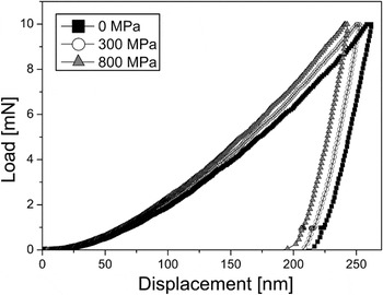
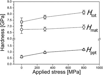
Next, we turned our attention to the change in nanoindentation hardness by the thermo-mechanical treatment. For a given sample, all the indentations were made within a grain to exclude the influence of grain boundary strengthening, which also made it possible to avoid the grain orientation effect on the strength. Representative nanoindentation load–displacement (P–h) curves obtained at the peak load of 10 mN are shown in Fig. 3. It is evident that, as the applied stress increases, the maximum displacement at the peak load decreases, implying that hardness increases. The nanoindentation hardness measured from each sample was 7.36 ± 0.33 GPa for σ = 0 MPa, 7.74 ± 0.16 GPa for σ = 300 MPa, and 8.14 ± 0.17 GPa for σ = 800 MPa. From these results, it was convinced that the thermo-mechanical treatment did not induce any strength degradation and the strength is even enhanced by the treatment. Note that the obtained nanoindentation hardness may be higher than conventional Vickers hardness (measured at much higher peak load) because of the well-known “indentation size effect,” i.e., an increase in hardness with decreasing indentation load and depth.Reference Nix and Gao18
Variations in nanoindentation load–displacement curve by the thermal–mechanical treatment.

To analyze the way the precipitates might affect strengthening responsible for the hardness variation, the contribution of each strengthening mechanism was investigated in terms of the critical shear stress required for cutting or bowing. As mentioned earlier, precipitation strengthening in a superalloy is usually controlled by cutting mechanism that can be subdivided into two models, i.e., WCD modelReference Brown, Ham, Kelly and Nicholson9 for small particles and SCD modelReference Huther and Reppich10 for large particles. For both cases, it is possible to estimate the critical shear stress necessary for cutting the precipitates based on the assumptions that a pair of edge dislocations travels in the <110> direction on the {111} plane and cut through the ordered γ′ precipitates in a disordered matrix.
In the case of WCD model appropriate for small particles, the critical shear stress for cutting can be given asReference Brown, Ham, Kelly and Nicholson9

where γ APB is the anti-phase boundary energy of the γ′ in the {111} plane, b is the Burgers vector of edge dislocation in the matrix, d is the particle diameter, f is the volume fraction of the γ′ particles, T is the line tension of the dislocation, and A is the numerical factor depending on the morphology of the particles (i.e., 0.72 for spherical particles).Reference Reppich6
For SCD model applicable to larger particles, the critical shear stress can be obtained byReference Huther and Reppich10

where w is a constant (of the order of unity) that accounts for the elastic repulsion between the strongly paired dislocationsReference Reppich6 and is considered as unity in this work.
To calculate Eqs. (3) and (4), the value of b, γ APB, G, and T should be known. In this study, b and γ APB were taken as 0.254 nm and 0.28 J m−2, respectively.Reference Jackson and Reed19 The shear modulus G [= 0.5E/(1 + ν)] was calculated using elastic modulus E = 221 GPa (of Inconel 740) and Poisson’s ratio ν = 0.35,Reference Pretorius and Nembach20 and T was estimated as 0.5Gb 2.Reference Brown, Ham, Kelly and Nicholson9 It is noteworthy that recently many simulation works (e.g., see Ref. Reference Mohles21 and Reference Rao, Parthasarathy, Dimiduk and Hazzledine22) have been made to provide the equations for more precisely calculating the critical shear stress for cutting in consideration of additional factors such as the long-range ordering and shapes of precipitates and the motion of the different-typed dislocations (i.e., screw and mixed dislocation). However, the effects of such factors have not been fully established yet and thus, in this work, we have taken the classical equations of (3) and (4) for simplifying calculations.
Although the cutting mechanism is known to be predominant mechanism for precipitation strengthening in a superalloy, previous worksReference Brown23, Reference Kocks24 reported that, in a limited condition (e.g., for large particles in an overaged condition), precipitation strengthening of superalloys can be also controlled by Orowan mechanism. It is well accepted that the critical stress necessary for Orowan (bowing) mechanism can be expressed asReference Orowan25

where λ is interparticle spacing between precipitates and is often simplified as

where f is the volume fraction of precipitates and d is the diameter of the spherical precipitate. As these f and d were already obtained experimentally (see Fig. 2), the critical shear stress required for Orowan mechanism can be easily evaluated according to Eqs. (5) and (6).
With the values of the critical shear stress calculated from Eqs. (3)–(5), one can estimate the contribution of each strengthening mechanism to the measured macroscopic hardness. By applying Tabor’s relationship and von Mises flow rule, the critical stress values for each strengthening mechanism (τ ppt) can be converted into the indentation hardnessReference Tabor26:

where H ppt is the amount of hardness increase, thanks to the precipitation strengthening.
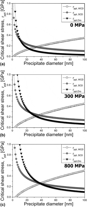
To find out the proper contributing mechanism, the τ ppt for each mechanism was plotted with the particle diameter, which is given in Fig. 4. For this theoretical calculation, the fraction of precipitates was fixed as average values for each sample (see Fig. 2). In Fig. 4, for a given diameter, the mechanism showing the lowest τ ppt value is supposed to mainly contribute to the strengthening. Note that the experimentally measured diameter was in the range of 20–60 nm. For all samples, with increasing particle size, there is a transition of the governing mechanism from WCD cutting to Orowan mechanism. The SCD cutting mechanism could be ruled out for entire range of particle diameter. In the figure, the maximum τ ppt (at the transition point from the WCD cutting curve to Orowan curve) indicates the maximum possible amount of the particle strengthening. It is interesting to note that the maximum τ ppt between WCD and Orowan curve increases more significantly with the applied stress vis-à-vis the value between WCD and SCD curve, i.e., the increase in the contribution of γ′ to the strengthening with increase in the applied stress is more pronounced in WCD–Orowan case rather than in WCD–SCD case. This trend might arise from the fact that the τ ppt for Orowan mechanism has higher sensitivity to volume fraction f than that for SCD cutting mechanism because the former and the latter are proportional to f/(1−f) and f 0.5, respectively.
Analytical calculations of the critical shear stress versus particle diameter: (a) 0 MPa, (b) 300 MPa, and (c) 800 MPa.

Finally, we have analyzed the contribution of H ppt change to the overall hardness change. Total (overall) hardness H tot can be described as

where H mat is the matrix hardness, which is the strength term contributed by other sources rather than γ′ precipitates (e.g., Peirls–Nabbaro stress, dislocation hardening, and solid solution strengthening by Co for this alloy). As mentioned earlier, grain boundary strengthening was excluded because all indentations were made at the interior of the grain. It is noteworthy that here we did not consider the role of carbides simply because their fraction is very low compared to γ′ fraction (for all examined samples). Also, we could not find any other important feature of phase transformations such as η phase precipitation. Note that thermodynamically calculated equilibrium (not shown here) indicated that η phase is not stable at 700 °C. While H tot was simply calculated from nanoindentation experiment according to Oliver–Pharr method,Reference Oliver and Pharr11 H ppt was determined in the following procedure: first, we directly compared the plot of size versus its fraction (Fig. 1) with the plot of size versus τ ppt (Fig. 4) to determine which size corresponds to which mechanism (WCD or Orowan mechanism). Next, we calculated the τ ppt for individual size in both the WCD regime and the Orowan regime according to Eqs. (3) and (5), respectively. Then, the overall τ ppt was determined in consideration of τ ppt of individual size and the fraction of each size. Finally, the obtained overall τ ppt was converted to H ppt by Eq. (7). Figure 5 exhibits the calculated H ppt and H mat together with H tot. It is obvious that the change in the H mat with the stress is very small compared with that in the H ppt. Especially, it is interesting to note that, although plastic deformation should increase the dislocation density and the strength (by strain hardening), the change in the average H mat between 300 and 800 MPa sample (from ∼6.78 to ∼6.94 GPa) is smaller than that in the average H ppt (from ∼0.97 to ∼1.19 GPa). From Fig. 5, it was believed that the overall strength enhancement by the thermo-mechanical treatment is seriously affected by the change in the amount of precipitation strengthening.
Summary of the measured nanoindentation hardness (H tot), the precipitation strengthening contribution to the hardening (H ppt), and the calculated matrix hardness (H mat).

IV. CONCLUSION
The influence of the high stress at high temperature on the γ′ precipitation behavior and its strengthening in Inconel 740 superalloy was investigated by using thermo-mechanically treated samples. Microstructural analysis revealed that, with increasing stress, the fraction of γ′ precipitates increased but their size was not significantly changed and remained in the range of 20–60 nm, which might be understood by considering the effects of the external stresses and the resulting elastic/plastic strains on the free energy barrier and the concentration of the nucleation sites for heterogeneous nucleation. Measurement of nanoindentation hardness showed that the strength was enhanced by the thermo-mechanical treatment. The hardness variation could be explained by analyzing the critical stress values for the governing precipitation strengthening mechanisms (i.e., cutting versus bowing). By dividing the overall hardness H tot into the matrix hardness H mat and the contributing amount of precipitation strengthening H ppt, it was proved that the change in the H ppt was largely responsible for the overall strength enhancement by thermo-mechanical treatment.
ACKNOWLEDGMENT
This work was supported by the Human Resources Development of the Korea Institute of Energy Technology Evaluation and Planning (KETEP) grant funded by the Korea government Ministry of Knowledge Economy (No. 20101020300460).