Introduction
Surface coating has been attracting researchers' attention by improving material properties and performances without changing bulk materials.[Reference Chalker, Bull and Rickerby1–Reference Ivanov, Lebedev and Pinahin9] The tribological and compression performance of a coating in many cases determines material applications in practice, since it plays an important role in surface fracture, wear, friction, fatigue, material lifetime, etc.[Reference Feng and Chen10–Reference Feng12] There has been an increasing interest in studying compression and tribology performance of coatings both in the scientific community and in industry, and the indentation and scratch tests become widely-used tools in this research process.
The full fields of material deformations and stresses in the coatings during indentation and scratch are very complex and unable to be determined experimentally due to the nonlinearity caused by multi-physics involved in the tests (e.g., large elastoplasticity, cracking, fracture, and wear) and the nonlinearity in geometry of a contact surface due to severe plastic deformation. The finite element method (FEM) serves as a powerful tool to reveal the detailed mechanical responses in the scratch and indentation processes. Pioneering FEM simulations on indentation and scratch tests, based on classic elastoplasticity, have been successful in both interpret experimental phenomena and help optimize designs.[Reference Feng and Chen10–Reference Bellemare, Dao and Suresh22]
Residual stresses commonly exist in engineering structures and parts due to thermal mismatch or mechanical/thermal processing, and they have significant effects on the mechanical behavior of materials, such as plasticity, fatigue, fracture, corrosion, wear, and friction.[Reference Lu23] In particular, when surface coating has different properties from bulk materials, the residual stresses can easily appear during manufacturing and assembling due to temperature changes, or in service. In many cases the residual stresses are complexly distributed in the materials, which makes a quantitative study challenging. Therefore, it is common to apply a homogeneous prestress field in materials to study the prestress effects on the materials' mechanical responses. This provides fundamental data on the effects of residual stresses since homogeneous prestress is a special and the simplest residual stress. In many cases, the definitions of prestress and residual stress are interchangeable in the literature (see Refs. Reference Jiang, Zhang, Yang, Jiang and Kang13,Reference Zhang, Cheng, Peng, Ma, Jiang, Hu and Chen14, and Reference Lu, Feng, Peng, Yang, Huan and Zhang24 and references mentioned therein). In addition to the inevitability of the appearance of residual stresses in many cases, residual stresses or prestress may be applied before the material is placed in service if it has better performance. Consequently, understanding the effects of residual stresses existing in engineering structures on mechanical performance is of great importance. In 2014, Lu et al. proposed a method that can be used to estimate the surface equibiaxial prestress of a material using instrumented sharp indentation.[Reference Lu, Feng, Peng, Yang, Huan and Zhang24] Furthermore, they successfully used the FEM to investigate the effects of the equibiaxial and non-equibiaxial prestress in the indentation test.[Reference Jiang, Zhang, Yang, Jiang and Kang13,Reference Zhang, Cheng, Peng, Ma, Jiang, Hu and Chen14] Similar to Refs. Reference Jiang, Zhang, Yang, Jiang and Kang13 and Reference Zhang, Cheng, Peng, Ma, Jiang, Hu and Chen14, this paper focused on FEM modeling and simulations in the indentation test. While Jiang et al.[Reference Jiang, Zhang, Yang, Jiang and Kang13] and Zhang et al.[Reference Zhang, Cheng, Peng, Ma, Jiang, Hu and Chen14] investigated the prestress in the bulk material instead of surface coating; the results from this paper show that the differences are very significant between bulk materials and thin films. Therefore, the first goal of this paper is to study the prestress effects on thin films as well as the effect of surface coating thickness during indentation. Prestress effects on scratch tests have recently attracted researchers' attention. In 2018, Jiang et al. experimentally investigated the effects of pre-stretch in scratch behavior of a low-density polyethylene (LDPE) film, and it was found that when the film is scratched parallel to the pre-stretch direction, the scratch performance of the LDPE film improved with an increasing pre-stretch level, and scratch resistance decreased with the increase of residual stress when the pre-stretch direction is perpendicular to scratch.[Reference Jiang, Wei, Cheng and Zhu25] In 2012, Tan et al. performed prestress scratching tests on a polished surface of SiC ceramics. It was found that the existence of prestress shortens the depth of median cracks and reduces the subsurface damage, and with increasing prestress in a proper range, the depth of median crack decreases and the propagation length of the lateral crack is limited.[Reference Tan, Jiang, Nie, Yang, Zhang and Peng26] While it is significantly important, FEM modeling of the prestress effects in the scratch test is rare if there is any at all, and studying the effects of prestress during scratch is another important goal of this paper. In this paper we develop three-dimensional indentation and scratch models to numerically investigate the effects of prestress on mechanical responses of thin films on a hard substrate by using FEM. The prestress discussed in this paper is compressive, and there is no special note, the word “prestress” means the compressive prestress in the rest of the paper. The results obtained show that mechanical responses of thin films during indentation and scratch tests are strongly dependent on both the prestress and the film thickness.
Model formulations
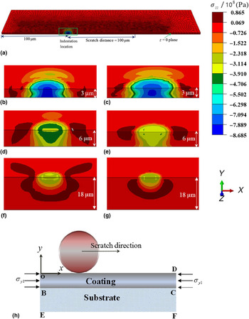
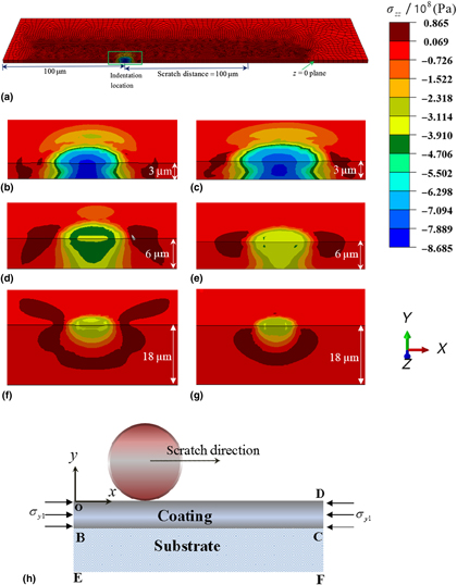
A schematic of the system of a substrate, a coating, and an indenter is shown in Fig. 1(h) where a Cartesian coordinate system is assigned. The x-axis is parallel to the scratch direction, the y-axis is pointing to the negative direction of the indentation (i.e., the out-of-coating direction), and the z-axis is pointing out of this figure. The z = 0 plane splits the structures into two symmetrical halves.
Distribution of the normal stress σ zzin the thin films at the indentation depth of 0.1 µm. (a) The mesh distribution in half a film, and the green box region in (a) is the same region as (b). (b), (d), and (f) With prestress σ xx = −σ y 1, and (c), (e), and (g) do not have prestress applied. The film thickness is 3 µm (b, c), 6 µm (d, e), and 18 µm (f, g), respectively. (h) Schematic of the scratch process on a prestressed film coated on a substrate.

The loadings are applied in three continuous steps. First, a homogeneous prestress at the coating is applied, and then the coating is attached to a substrate. Second, a vertical external force F n is continuously exerted along the y-axis on the spherical indenter to compress it into the coating surface, which is called the indentation step. Third, a horizontal external force F t along the x-axis and a moment M z are applied to move the indenter in the x-axis direction at a fixed indentation depth without the indenter rotation, which is called the scratch step. The scratch under a constant indentation depth is widely employed in both experiments and FEM simulations on scratch tests.[Reference Feng and Chen10–Reference Feng12]
In Fig. 1(h), the initial thickness of the coating in the undeformed configuration is considered 3, 6, and 18 µm, respectively, and the coating width along the z-axis and the length along the x-axis is 160 and 300 µm, respectively. The radius of the spherical indenter r is 200 µm which is a common geometry for the indenter as defined in European Standard EN 10109-2,[Reference Holmberg, Laukkanen, Ronkainen, Wallin and Varjus20] and the indenter is indented and scratches at the middle of the thin film width. This system geometry is consistent with the previous study.[Reference Feng and Chen10–Reference Feng12] The coating thickness in a few to several tens of micrometers is also commonly used in both FEM and experiments for the scratch tests.[Reference Bucaille, Gauthier, Felder and Schirrer18,Reference Holmberg, Laukkanen, Ronkainen, Wallin and Varjus20,Reference Li and Beres21] The following material properties were used for the metallic coatings[Reference Feng11,Reference Ott, Blue, Santella and Blau27] : yield strength  $\sigma _{{\rm y}1} = 234{\kern 1pt} {\kern 1pt} {\kern 1pt} {\kern 1pt} {\rm MPa}$, Young's modulus E 1 = 74 GPa, and v 1 = 0.3. For the high-speed steel substrate[Reference Holmberg, Laukkanen, Ronkainen, Wallin and Varjus20]:
 $\sigma _{{\rm y}2} = 4.1{\kern 1pt} {\kern 1pt} {\kern 1pt} {\kern 1pt} {\rm GPa}$, v 2 = 0.29, and
 $E_2 = 200{\kern 1pt} {\kern 1pt} {\kern 1pt} {\kern 1pt} {\kern 1pt} {\rm GPa}$. Coulomb friction coefficient is μ = 0.3. The elastic modulus and yield strength are much larger in the substrate than those in the soft coating, and under the loading used in this paper, the substrate is under extremely small elastic deformation without plasticity, which does not affect the deformation of soft thin film.[Reference Feng and Chen10–Reference Feng12] Therefore, the substrate can be considered a rigid body. The indentation or scratch depth is 0.1 µm. All results discussed in this paper are at a depth of 0.1 µm, and the ratio between indentation/scratch depth and the indenter radius is 1/2000. The size of the thin film is described in micrometers above. If the size of the scratch system and indentation depth are multiplied by n, the patterns of stress fields will be the same as in this paper and the applied force will be changed from F n (or F t) to n 2 · F n (or n 2 · F t). Because of the symmetry with respect to the z = 0 plane, only half of the structure will be analyzed.
In traditional Coulomb friction, the slippage on the contact surface starts only when the magnitude of the friction stress τ, τ = |τ| reaches the critical friction stress τ crit = μσ n where σ n is the normal contact stress and μ is the traditional Coulomb friction coefficient. In addition, once friction stress τ reaches the shear yield strength of material  $\tau _{\rm y}\, = \,\sigma _{\rm y}/\sqrt 3 $ (von Mises yield condition is utilized and σ y is the yield strength) in the plastic state, slippage can also initiate even if τ < μσ n. Therefore, the traditional Coulomb friction can be modified by defining the critical friction stress as
 $\tau _{{\rm crit}}\, = \,\min \,(\mu \sigma _{\rm n},{\kern 1pt} {\kern 1pt} {\kern 1pt} {\kern 1pt} \tau _{\rm y})$, and when the friction stress τ reaches τ crit the slippage can occur. A total system of friction equations can be found in previous models,[Reference Feng and Chen10,Reference Feng and Levitas28] and it is used for the contact surface between the indenter and thin film during the indentation and scratch steps. The cohesion condition between the contact surfaces of the film and substrate is used, and these two surfaces are always tied together and there is no sliding between them.
The rigid body assumption for the indenter is accepted in all pioneering FEM models in scratch tests in the literature, which is also used in this paper. The elastoplastic models introduced below will be used for both the substrate and coating, while the high-speed steel substrate is almost rigid under the loading applied in this paper. The position vector of a particle in the current deformed configuration  ${\bi r} = {\bi r}({\bi r}_0,{\kern 1pt} {\kern 1pt} {\kern 1pt} {\rm t})$ is described by a function of the current time instant t and the initial position vector r 0 in the reference undeformed configuration at the initial time t0. As with Ref. Reference Feng, Levitas and Hemley29, the deformation gradient F = ∂r/∂r 0 can be multiplicatively decomposed into a plastic F p contribution and a symmetric elastic stretch tensor V e as F = V e · F p. The small elastic deformation assumption ε e = V e − I (I is the second-rank unit tensor) is used here, but the material rotations and plastic strains are allowed to be large and considered in the deformation gradient F p. A complete system of equations is summarized below.
The velocity gradient 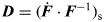 ${\bi D}= {\rm (}\dot{{\bi F}}\cdot {\bi F}^{-1}{\rm )}_{\rm s}$ is additively decomposed into elastic (subscript e) and plastic (subscript p) contributions:
 $${\bi D} = {\bi D}_p + \mathop {{\bi \varepsilon} _e} \limits^\nabla. $$
Subscript s stands for symmetrization of a tensor, and  $\mathop {{\bi \varepsilon} _{\rm e}}\limits^{\rm \nabla} $ is the Jaumann objective time derivative of the elastic strain ε e.
Hooke's law for deviatorics and volumetric (negative pressure p) components of the Cauchy stress T:
 $${\bi s} = 2G{\kern 1pt} {\kern 1pt} dev{\kern 1pt} {\bi \varepsilon} _e ;\quad -p = {\kern 1pt} \displaystyle{{\sigma _{xx} + \sigma _{yy} + \sigma _{zz}} \over 3} = K\varepsilon _{v {\kern 1pt}}, {\kern 1pt} $$
where  ${\bi s} = dev{\bi T}$;
 $\varepsilon _{{\rm v}{\kern 1pt}} $ is the volumetric strain; G and K are the shear and bulk moduli, respectively.
Von Mises yield condition obeys
 $$\sigma _i = \left( {\displaystyle{3 \over 2}{\rm {\bf s}}:{\rm {\bf s}}} \right)^{0.5} \le \sigma _y, $$
in which σ y is the material yield strength; σ i is the von Mises effective stress: 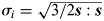 $\sigma _i = \sqrt {3/2{\bi s}:{\bi s}} $.
In the plastic region, plastic flow rule follows:
 $$\sigma _i\, = \sigma _{\rm y}\to {\bi D}_{\rm p} = \lambda {\bi s}\quad {\rm and}\quad \lambda \, \ge \,0.$$
The parameter λ is iteratively updated by satisfying the von Mises yield condition in Eq. (3), and the Newton–Raphson method and radial return method are frequently used for solving λ.
In the elastic region:
 $$\sigma _i\, \lt \sigma _{\rm y}\to {\bi D}_{\rm p} = 0\quad {\rm and}\quad \lambda \, = \,0.$$
Equilibrium equation yields
 $$\nabla \cdot {{\bi T}} = {\bf 0}.$$
In this paper the material is considered isotropic. When the size of the thin film is reduced to at or below several tens of nanometers the material may become single crystal. Anisotropy of single crystal theory can be found in Ref. Reference Feng, Bronkhorst, Addessio, Morrow, Cerreta, Lookman, Lebensohn and Low30.
Numerical results and discussion
In this section three-dimensional indentation and scratch models with prestress proposed in the previous section are simulated and discussed by using finite element code ABAQUS 6.14. Similar to our previous models,[Reference Feng and Chen10–Reference Feng12] an 8-node linear brick element (C3D8R) is used in the simulations of this paper. Due to symmetry on the z = 0 plane only half of the structure is considered in simulations and discussion. As seen in Fig. 1(a), the front surface is the z = 0 plane. The number of elements is around 100,000 for the thin film, with 6–10 elements in the thickness direction. As shown in Fig. 1(a), the distance of the indentation location and the left boundary of film is 100 µm, which can exclude the boundary effects. The numerical results for the scratch test are obtained at the location when the indenter scratches 100 µm from the indentation location to exclude effects from the indentation location [see Fig. 1(a)]. Compared with the thin film strength (e.g., yield strength and Young's modulus) the substrate is a very hard material in this paper, and therefore the deformation in the substrate is completely elastic and extremely small. Therefore, we will only discuss the results for the soft thin film as in Refs. Reference Feng and Chen10–Reference Feng12. For Figs. 1–3 the homogeneous uniaxial compressive prestress in the scratch direction (i.e., the x-axis) σ xx = −σ y 1 is applied, where σ y 1 is the yield strength of the films. For Fig. 4, in addition to the compressive prestress σ xx = −σ y 1, we also apply the compressive prestress σ zz from 0 to − σ y 1, so the prestress is biaxial. This helps us to understand the effects of the magnitudes of prestress in the z axis in a range (i.e., when it varies from zero to the maximum compressive prestress). In all cases the prestress is homogeneously distributed in the surface coating, and no plastic deformation occurs before the indentation step starts. The results may be very different if both plastic deformation and prestress are applied simultaneously, but this is not the focus of this paper. In addition, the results discussed in this paper are under an indentation or scratch depth of 0.1 µm for both the indentation and scratch tests.
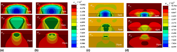
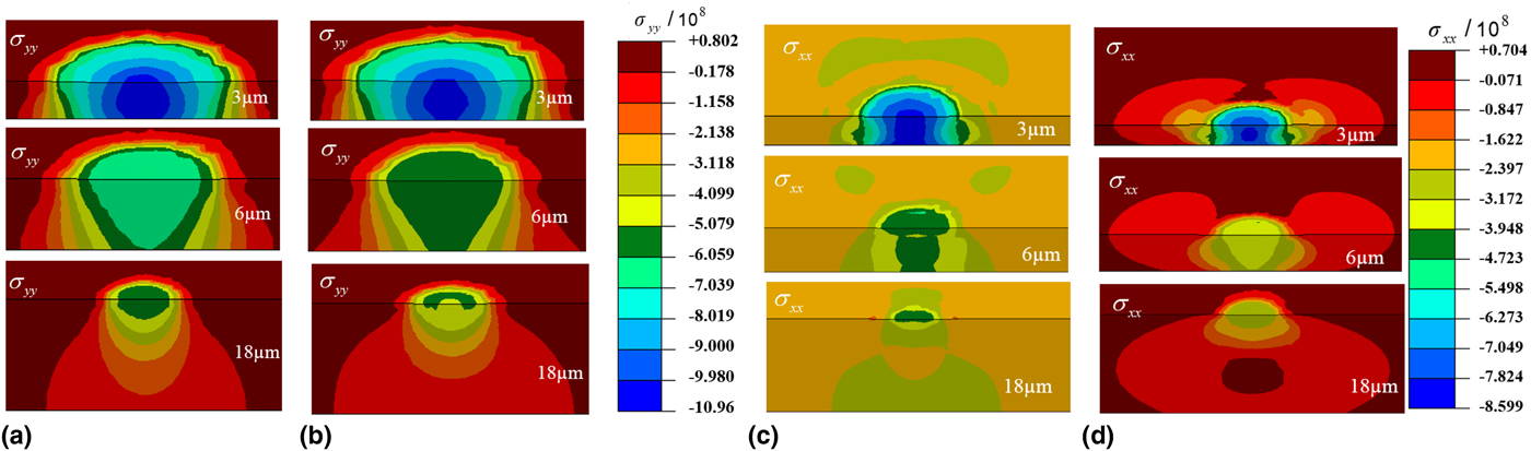
Distributions of the normal stress σ yy(a, b) and σ xx (c, d) of the thin films in the indentation test. (a) and (c) have the prestress σ xx = −σ y 1, and (b) and (d) are without prestress applied. The thickness of the films is 3, 6, and 18 µm.
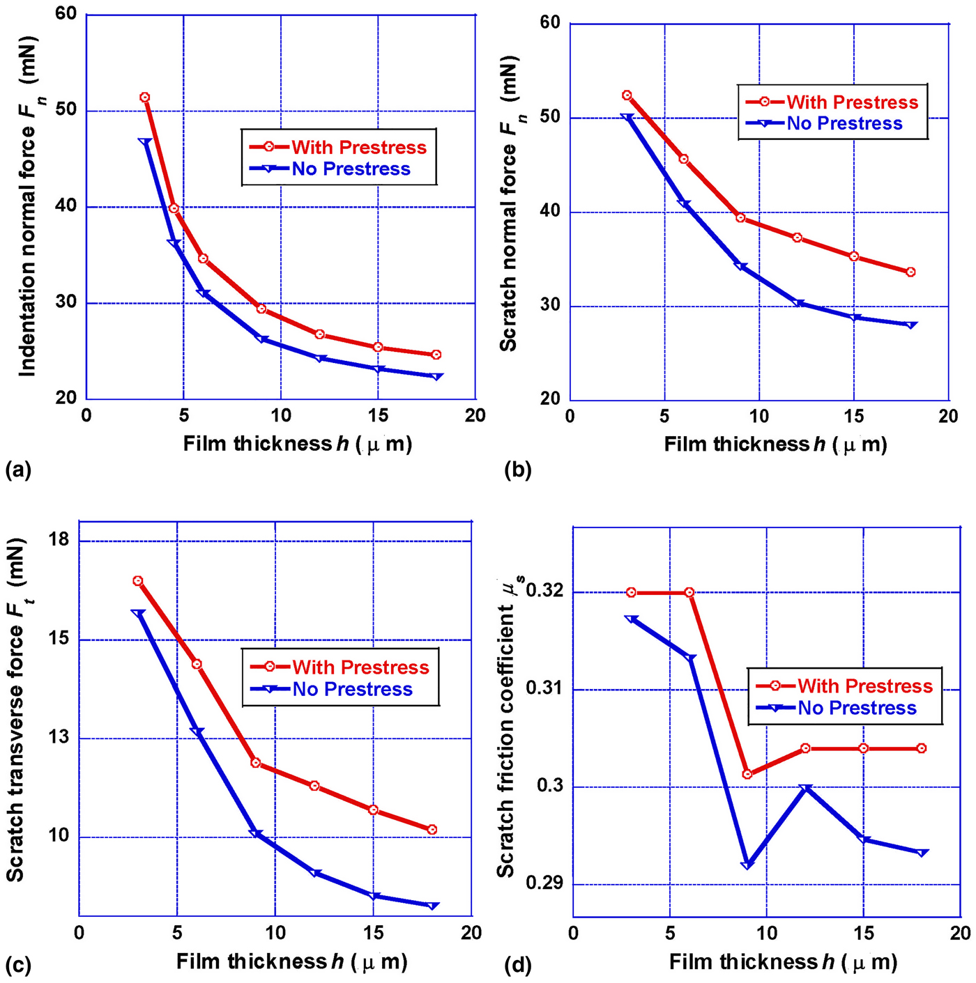
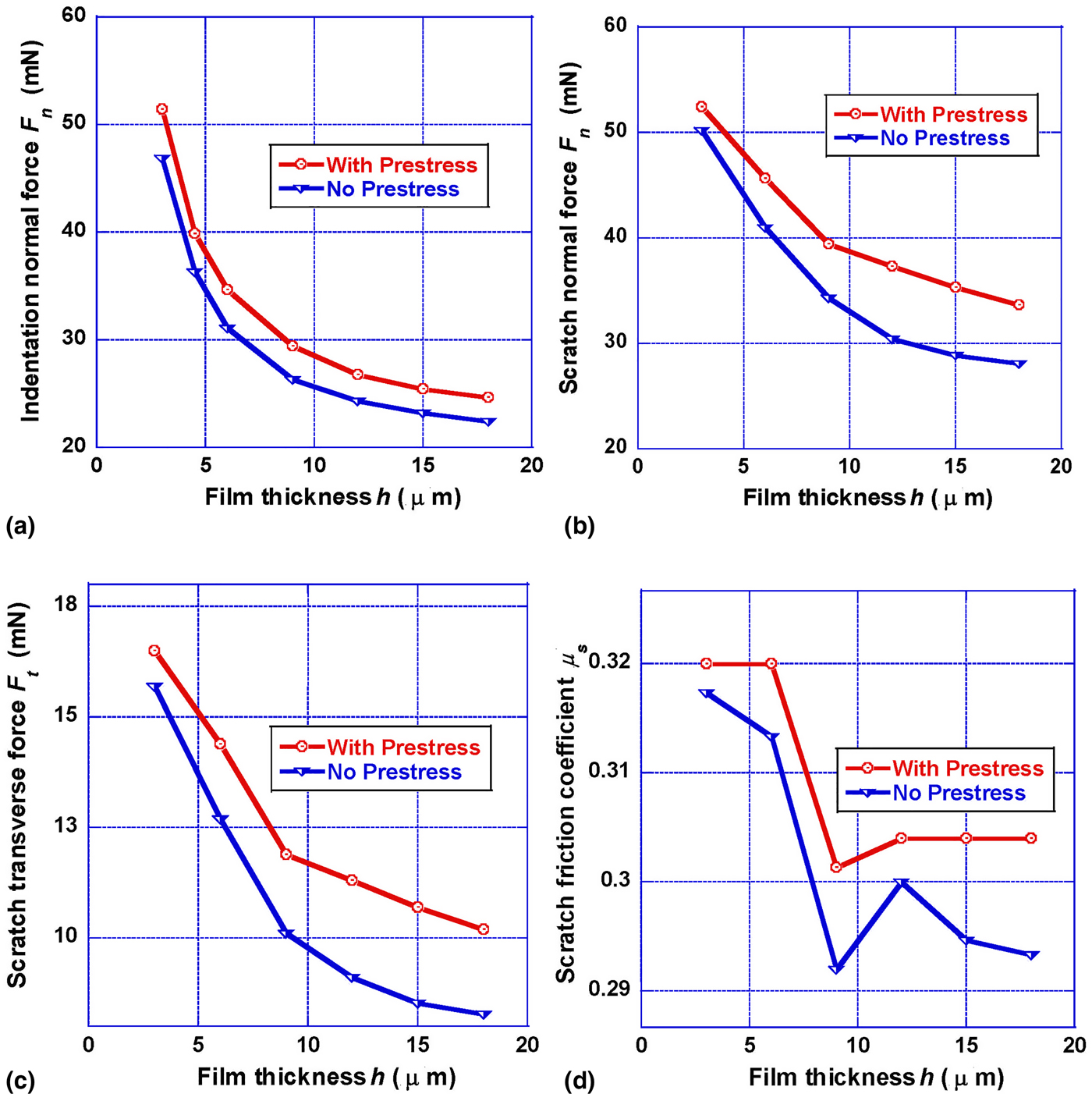
(a) Indentation force F n applied on the indenter along the y-axis versus the film thickness for prestressed (σ xx = −σ y 1) and non-prestressed films in the indentation test. Normal force F n (b) and transverse force F t (c) applied on the indenter for the scratch distance 100 µm for prestressed (σ xx = −σ y 1) and non-prestressed films at the scratch depth of 0.1 µm. (d) The scratch friction coefficient μ s :μ s = F t/F n.
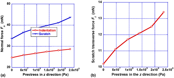
Normal F n (a) and transverse F t (b) force applied on the indenter when the scratch distance is 100 µm and scratch depth is 0.1 µm for prestressed σ xx = −σ y 1 and prestressed σ zz varying from 0 to  $\sigma _{y 1}{\kern 1pt} \;(compressive)$. In (a) the normal force F n for the indentation test is also plotted. This film thickness is 18 µm.
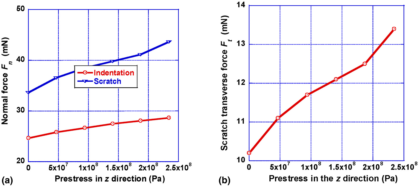
Figure 1 presents the distribution of the normal stress σ zzof the thin film in the indentation test. Figure 1(b) is the zoomed-in region of the green rectangle in Fig. 1(a). This nonzero stress region is quite small compared with the total volume of the thin film, and thus the boundary effects are excluded from our simulations. It is found from Fig. 1 that the patterns of the normal stress σ zz distribution in the high-stress (large absolute values) region between the prestressed and non-prestressed films are very similar. However, the stress σ zz is higher in the prestressed film, while there is no prestress applied in the z-axis. In the low-stress region the patterns of σ zz are very different between with prestress and without prestress. In particular with a large thickness (e.g., 18 µm) the patterns between them are completely different. One of the important reasons why prestress applied in one direction affects the stress in another direction is that the von Mises effective stress σ i is limited by the yield strength in shear, and thus the difference between two normal stresses cannot increase without a limit. In Ref. Reference Zhang, Cheng, Peng, Ma, Jiang, Hu and Chen14 the prestress effects in the bulk material are discussed with the Coulomb friction conditions. In this paper we extend the models not only for bulk material but also for thin films, so that combined Coulomb friction and plastic friction are considered. In Fig. 1, with an increase in film thickness, the patterns of the σ zz distribution vary significantly. There are two obvious features: first, with an increase in thickness, the stress concentration reduces and the thinner film has the larger stress at a fixed indentation depth of 0.1 µm; second, the normal stress gradient along the thickness direction increases with the increase of film thickness. Specifically, σ zz only varies very slightly in the film having 3 µm thickness, while in the film with 18 µm thickness σ zz is very high at the contact surface but close to zero at the bottom of the film.
Figures 2(a) and 2(b) presents the distribution of the normal stress σ yy of the thin film in the indentation test. In comparison with σ xx and σ zz, σ yy is the largest normal stress in the absolute value due to the compression of the indenter into the film. The patterns of all three normal stress distributions are quite different. Similar to σ zz, the stress concentration of σ yy is larger with prestress than that without prestress. With increasing coating thickness the stress σ yy concentration reduces, and the stress gradient increases in the thickness direction. The patterns of the σ yy distribution with prestress and without prestress are almost the same in both the high- and low-stress zones while the patterns of σ xx (or σ zz) are very different between prestressed and non-prestressed films in the low-stress zones. As shown in Figs. 2(c) and 2(d), the minimum normal stress σ xx in absolute value is equal to the yield strength σ y 1 of the prestressed film, while it is zero for the non-prestressed film. The stress concentration for σ xx is larger in the prestressed film than that in the non-prestressed film, which is consistent with σ yy and σ zz. The stress σ xx gradient along the thickness direction in the film with 18 µm thickness is larger than that in the 3 and 6 µm films. For the prestressed film the number of different colors in the σ xx is less than the number in the non-prestressed film and the stress σ xx gradient in the x and y directions is smaller in the prestressed film since there are less colors, which is different from the cases about σ yy and σ zz.
Figure 3(a) plots the vertical force F n applied on the indenter along the y-axis for prestressed and non-prestressed films at the indentation depth of 0.1 µm. F n is equal to the integration of the contact stress at the film along the direction normal to the undeformed film surface (i.e., along the y-axis):
 $$F_{\rm n} = \int {{\bi \tau} _y} da + \int {\sigma _{{\rm n}y}} da.$$
In Eq. (7), subscript y represents the components of the friction stress τand the normal contact reaction σ n along the y-axis, and  $\int {da} $ is the area of the contact surface. It is found in Fig. 3(a) that to reach the same indentation depth, the normal force F n is much larger in the prestressed film than that in the non-prestressed film. Therefore, to cause the same amount of deformation of the thin film, a larger force should be applied on the prestressed film, and the material will become harder to deform for the prestressed film. For example, for a film thickness from 3 to 18 µm, the increase in the normal force F n for the prestressed film is 10%–12% under the indentation depth 0.1 µm, in comparison with the non-prestressed film. In addition, with an increase in the film thickness the normal force F n reduces drastically for very thin films; then the rate of the F n reduction becomes slow and then becomes a constant for very thick films.
The discussion on Figs. 3(b)–3(d) and 4 is focused on the scratch test, and the results are obtained when the scratch distance from the initial indentation location is 100 µm as shown in Fig. 1(a). For the scratch test the indenter scratches on the film with a constant scratch depth of 0.1 µm. The scratch normal force is also determined by Eq. (7). While the indenter displacement in the y-axis is 0.1 µm for both indentation and scratch tests, Figs. 3(a) and 3(b) show that the normal force F n in the scratch test is higher than F n in the indentation test. Due to the indenter displacement in the y-axis, the film material in the front of the scratch is extruded out and film thickness is higher than the undeformed initial thickness. When the scratch continues the lump due to extrusion has to be scratched down to the indenter, and it requires an additional normal force, compared with compressing a flat surface in the indentation test. This is the reason why the normal force F n in the scratch is higher than F n in the indentation. For the film thicknesses varying from 3 to 18 µm, the increasing ratio of F n for scratch from the non-prestressed to prestressed film is about 4%–23%, but it is close to a constant 11% for the indentation test. This difference between scratch and indentation is also caused by severe scratch deformations. For a very thin coating the difference in F n between a prestressed and non-prestressed film during scratch is small.
Figure 3(c) plots the scratch transverse force F t for the prestressed and non-prestressed films during the scratch test. F t is the resistance force for the indenter moving along the scratch direction (i.e., along the x-axis), and it can be defined by
 $$F_{\rm t} = \int {{\bi \tau} _x} da + \int {\sigma _{{\rm n}x}} da,$$
where subscript x stands for the components of the friction stress τ and the normal contact stress σ n along the x-axis. The scratch coefficient μ s in Fig. 3(d) is defined by μ s = F t/F n.
For the indentation test, F t is zero while τx and σ n x are both nonzero at the contact surface due to deformation of contact surface. For the scratch test the variation of F t with the increasing film thickness has the same trend with the variation of F n, therefore, the variation of μ s = F t/F n is small during thickness changes as shown in Fig. 3(d). The difference in F t between the prestressed and non-prestressed films is small for a thin film but it can be larger when the thickness reaches 9 µm. The resistance of the prestressed film for scratch becomes larger, and the indenter is more difficult to move on the prestressed film, in comparison with the case for the non-prestressed film. For thicknesses varying from 3 to 18 µm the increasing ratio of F t for the prestressed film during scratch is about 5%–25% from the non-prestressed film. The scratch friction coefficient also represents the sliding capacity at the contact surface, and Fig. 3(d) shows that it is more difficult to slide on a prestressed film than a non-prestressed one due to a larger scratch friction coefficient. It is noted that μ s in Fig. 3(d) can be lower than the Coulomb friction coefficient 0.3 in this paper, while the plastic deformation of contact surface in many cases increases the scratch friction coefficient. The scratch friction coefficient being lower than Coulomb friction for a soft coating is due to plastic slippage, in which the friction stress cannot surpass the yield strength in shear but the normal contact pressure on the contact surface can continually increase. This is similar to the experiment[Reference Sinha and Lim6] and simulation[Reference Feng and Chen10] findings that the scratch friction coefficient can decrease with an increase of indentation depth (or plastic deformation). For Figs. 1–3 the prestress is uniaxial along the scratch direction. Figure 4 shows the normal force F n in the indentation and scratch, and the scratch transverse force F t, for the biaxial prestress in which the compressive prestress in the x-axis is σ y 1 and the compressive prestress in the z-axis σ zz varying from 0 to σ y 1. It is found from Fig. 4 that indentation normal force F n is significantly smaller than scratch normal force F n. With an increase of prestress σ zz the film deformation for indentation as in Fig. 4(a) and for scratch as in Fig. 4(b) becomes more difficult, and higher external forces (e.g., F n and F t) are required to deform the material and slide at the contact surface.
Conclusions
Three-dimensional indentation and scratch models with prestress are modeled and simulated by using the finite element code ABAQUS 6.14. The strong effects from the coating thickness and prestress are found for both the indentation and scratch tests.
The uniaxial compressive prestress is applied in the scratch direction, and the scratch and indentation depth is fixed as a constant at 0.1 µm. For the indentation test the patterns of normal stress distributions among σ xx, σ yy and σ zz are very different. The patterns of the normal stress σ zz in the high-stress region between the prestressed and non-prestressed films are very similar, but they are very different in the low-stress zone. With an increasing film thickness the stress concentration σ zz reduces, and the σ zz gradient along the thickness direction increases. σ yy is the largest normal stress due to the compression of the indenter into the film. The stress concentration of σ yy is larger with prestress than that without prestress, and the patterns of the σ yy distribution in the prestressed and non-prestressed films are very similar. The range (i.e., the number of different colors in the legend) of σ xx for the prestressed film is smaller than the range for the non-prestressed film and the stress σ xx gradient in the x and y directions are smaller in the prestress film, which are different from the cases for σ yy and σ zz. In addition, with an increase of the film thickness but for the same indentation depth, the normal force F n applied on the indenter reduces drastically at the beginning; then the rate of the F n reduction becomes slow and then becomes constant for the very thick films. Compared with the non-prestressed film, for film thicknesses from 3 to 18 µm, the increase in the normal force F n is 10%–12% from the non-prestressed to prestressed film.
For the scratch test with or without a uniaxial prestress, the normal force F n in the scratch test is higher than F n in the indentation test. For film thicknesses from 3 to 18 µm, the increasing ratio of F n for scratch from the non-prestressed to prestressed film is about 4%–23%. For a very thin coating, the difference in the normal force F n (or transverse force F t) between prestressed and non-prestressed films during scratch is small but it can be large for a thick film. The scratch resistance of the prestressed film becomes larger, and the indenter is more difficult to move transversely, in comparison with the case for the non-prestressed film. The scratch friction coefficient is larger with prestress than without prestress. With an increase of compressive prestress σ zz and a fixed prestress σ xx = −σ y 1, the film deformation for indentation and slippage at the contact surface for scratch become more difficult, which is consistent with the case with uniaxial prestress. In this paper, we focus on the prestress as compressive one, when the prestress is tensile, a decreasing stress concentration, and the smaller normal force F n for indentation test would be expected since the prestress sign is changed from the current study, in comparison with the case without prestress. The results obtained from this paper show that mechanical responses of thin films during indentation and scratch are strongly dependent of the prestress and the film thickness, and they are beneficial to understanding a surface coating's performance and improving the modeling and simulations for materials under prestress.
Acknowledgment
The authors gratefully acknowledge support for this work partially from Los Alamos National Laboratory Advanced Simulation and Computing program.