1. Introduction
In recent years, wireless power transfer (WPT) is gaining a growing interest both in academic and industrial research as a promising technology which enables the wireless recharge of electronic devices [Reference Marques and Borges1–Reference Monti, Corchia, De Benedetto and Tarricone5].
In fact, WPT allows overcoming problems related to the use of recharge based on a cable connection to the power source, this being crucial in all the applications where it is complicated, or even impossible, to physically access the device to be charged.
In this context, particularly attractive is the use of WPT for recharging embedded devices such as medical implants [Reference Chen, Liu and See6–Reference Monti, De Paolis, Corchia, Mongiardo and Tarricone19] or sensors [Reference Mayordomo, Dräger, Antonio Alayón and Bernhard20, Reference Chen, Yang and Luo21]. For these applications, a crucial aspect is the variability of the electric properties of the propagation channel. In this regard, the best choice appears to be the use of a WPT link based on a resonant inductive coupling [Reference Monti, Arcuti and Tarricone16–Reference Liu, Yang, Jiang, Ruan and Chen23]. In fact, the adoption of a resonant scheme combined with a magnetic coupling allows maximizing the efficiency of the link while minimizing the dependence of the performance on the electric properties of the surrounding environment.
Additionally, in order to improve the performance of the inductive resonant WPT link, a viable strategy consists in using one or more relay elements (i.e. an additional coil not directly connected to the source or to the load) [Reference Ranaweera, Duong, Lee and Lee24–Reference Zhong, Zhang, Liu and Hui27].
In this regard, even though the case of a resonant inductive WPT link using three or four resonators has been deeply investigated in the literature, to the best knowledge of the authors a closed-form expression of the efficiency in terms of the geometrical parameters of the link has not been yet derived for the general case.
In more detail, in most papers only the coupling between adjacent coils has been taken into account. However, for recharging embedded devices, the most suitable configurations are the ones where one or more relays are coplanar to either the transmitting or the receiving resonators. For these configurations, all the couplings among the coils have to be taken into account.
In this regard, interesting results have been reported in [Reference Jolani, Yu and Chen28], where a four-resonator link has been considered. More specifically, the link analyzed in [Reference Jolani, Yu and Chen28] consists of two pairs of coplanar resonators having a planar structure and a square geometry.
In this paper, the results reported in [Reference Jolani, Yu and Chen28] have been extended to the case of a three-coil link using a circular loop geometry. In more detail, a closed-form analytical expression of the efficiency is derived. The derived formula is valid for any position of the relay element between the transmitting and the receiving resonators, this comprising the case where the relay element is coplanar to either the transmitting or the receiving resonators. This enables the optimization of the efficiency by using general purpose optimization tools and in a negligible computational time, thus representing an attractive alternative to the optimization of the link through time-consuming full-wave simulations [Reference Monti, De Paolis, Corchia, Tarricone and Mongiardo18, Reference Monti, De Paolis, Corchia, Mongiardo and Tarricone19].
As per the adoption of the presented algorithm for optimizing WPT links for embedded devices, it is worth underlining that, in view of the adoption of a magnetic coupling, the performance of the link is independent of the electric properties of the propagation channel. In other words, the performance of the link is not affected by the medium interposed among the resonators, be it a human tissue, cement or air. For instance, referring to a link for recharging a medical implant, in [Reference Monti, De Paolis, Corchia, Mongiardo and Tarricone19] it is demonstrated that the performance of the link is strongly affected by the distance between the two resonators while it is independent of the presence of the human tissues. These results suggest that the presented algorithm can be adopted as it is for optimizing the link in air; possible effects on the performance of the specific electric properties of the propagation channel, which could be induced by a parasitic capacitive coupling, could be verified just before realization.
In order to validate the effectiveness of the proposed algorithm, numerical and experimental data referring to an application imposing specific constraints on the dimensions of the receiving resonator are reported and discussed.
The paper is organized as follows. In section “Analytical model”, the analyzed problem is briefly described and analytical formulas are reported for the relevant quantities. In section “Optimization process” the proposed optimization algorithm is described. Analytical and numerical results are given in section “Analytical results” and “Full-wave and circuital simulation results”, respectively. Experimental data are reported in section “Experimental results” and some conclusions are drawn in section “Conclusions”.
2. Analytical model
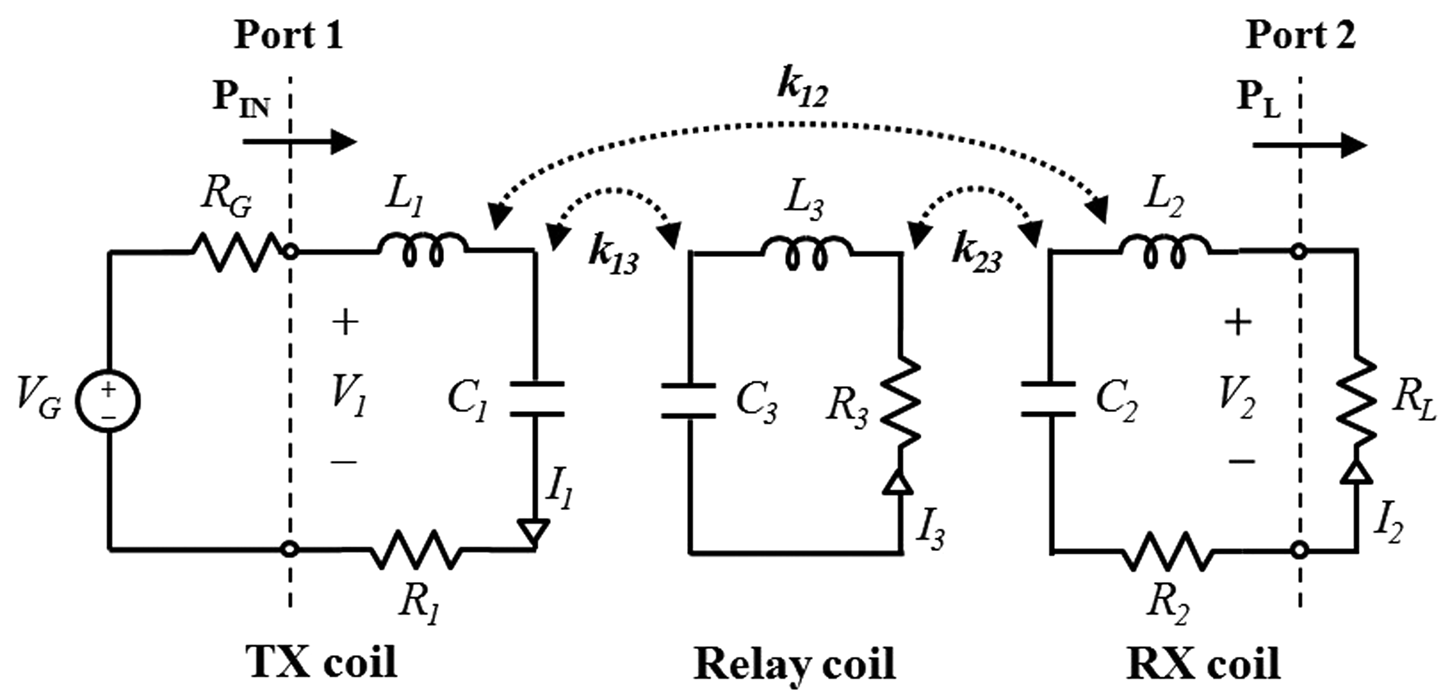
The equivalent circuit of the analyzed problem is illustrated in Fig. 1. It is a 3-coil WPT link consisting of a transmitting (TX) coil, a receiving (RX) coil, and a relay coil, in the following denoted by 1, 2, and 3, respectively.
Equivalent circuit of the 3-coil WPT link.

It is assumed that the source is a sinusoidal voltage generator with angular frequency ω 0 and internal resistance R G and that the load is a resistor R L.
The circuital elements R i and L i, denote the resistance and the inductance of the i th coil. The lumped capacitors C i are used to tune the resonance frequency to the desired value. The coupling coefficient between the i th coil and the j th coil is denoted by k ij (i = 1, 2, and 3, j = 1, 2, and 3).
Furthermore, it is assumed that the three coils are synchronous (i.e. they have the same frequency of resonance f 0 = 13.56 MHz).
The quality factor of the i th coil (i = 1, 2, and 3) is defined as follows:
 $$Q_i = \displaystyle{{\omega _{0i}L_i} \over {R_i}}\; \quad (i = 1,2,3),$$
while the load quality factor (Q L) and the loaded quality factor of the receiving coil (Q 2L) are given by:
 $$Q_L = \displaystyle{{\omega _{02}L_2} \over {R_L}},$$
 $$Q_{2L} = \displaystyle{{Q_2Q_L} \over {Q_2 + Q_L}}.$$
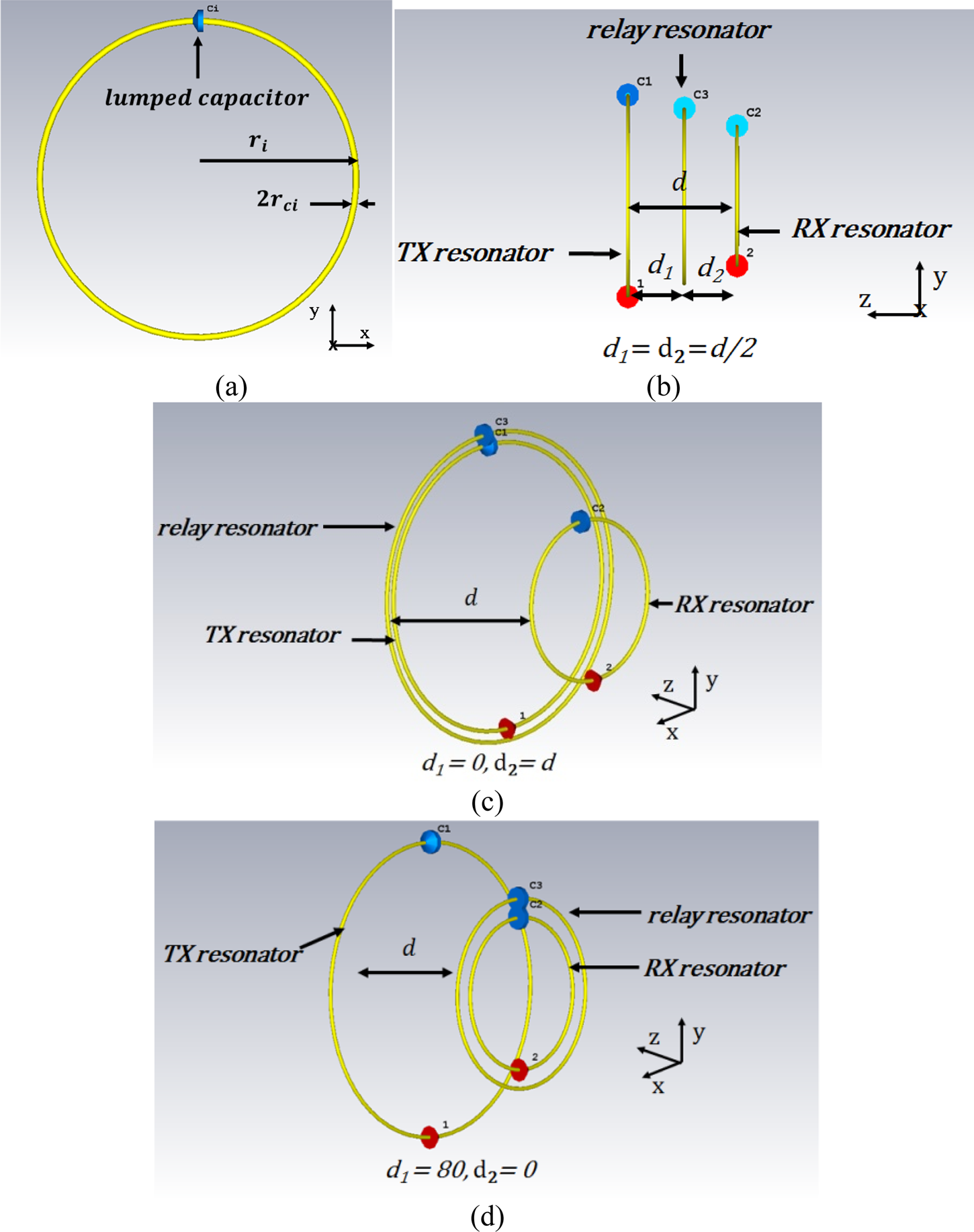
Referring to the practical implementation of the link illustrated in Fig. 2, in the next section, the analytical expressions of the circuital parameters are derived for the case where each resonator consists of a circular loop loaded by a lumped a series compensating capacitor.
(a) Geometrical parameters of the single loop; the distance between the TX and the RX resonators is d = 80 mm, the radius of the RX coil is r 2 = 50 mm + r c, while r c is 1.35 mm. (b), (c), and (d) Geometries of the three analyzed cases: (b) test case #1 (z 12 = d, z 13 = z23 = d 1 = d/2); (c) test case #2 (z 12 = d, z 13 = 0, z23 = d); and (d) test case #3 (z 12 = d, z 13 = d, z 23 = 0).

3. Analytical expressions of the circuital parameters
Referring to Figs 1 and 2, the total resistance R i of the i th loop (i = 1, 2, and 3) consists of the radiation resistance, R irad, and the loss resistance, R iohm [Reference Hu and Georgakopoulos29]:
 $$R_i = R_{iohm} + R_{irad}\quad \lpar {i = 1,2,3} \rpar,$$
 $$R_{iohm} = \displaystyle{{r_i} \over {r_{ci}}}\sqrt {\mu _0\rho \pi f_{0i}} \quad \lpar {i = 1,2,3} \rpar,$$
 $$R_{irad} = 320\pi ^6\left( {\displaystyle{{\,f_{0i}r_i} \over c}} \right)^4\quad \lpar {i = 1,2,3} \rpar,$$
where μ 0 is the free space magnetic permeability, ρ is the material resistivity, f 0i is the resonance frequency, r i and r ci are the radius and the cross-sectional radius of the i th loop.
While, the equivalent inductance of the i th circular loop (L i, i = 1, 2, and 3) can be calculated according to the following formula [Reference Hu and Georgakopoulos29 Reference Liu, Hu and Georgakopoulos30]:
 $$L_i = \mu _0r_i\left[ {\ln \left( {\displaystyle{{8r_i} \over {r_{ci}}}} \right)-2} \right]\quad \lpar {i = 1,2,3} \rpar.$$
The capacitors C i are set so to make the loops resonating at the desired angular frequency ω 0 (i.e. ω 0 = 2πf 0):
 $$C_i = \displaystyle{1 \over {\omega _0^2 L_i}}\quad (i = 1,2,3)$$
As per the mutual inductances M ij between the coils i and j (i = 1, 2, and 3, j = 1, 2, and 3), they are related to the coupling coefficients by the relation  $M_{ij} = k_{ij}\sqrt {L_iL_j} $.
In this paper the expression reported in equation (7) of [Reference Raju, Rongxiang, Chan and Yue31] is assumed for M ij.
In more detail, the most crucial case occurs when the two loops are coplanar. In this case, equation (7) of [Reference Raju, Rongxiang, Chan and Yue31] leads to a large error that can be reduced by expanding the formula to a higher order [Reference Jolani, Yu and Chen28]. For instance, the expression of M ij provided by equation (7) of [Reference Raju, Rongxiang, Chan and Yue31] when an expansion up to the 50th order is used is:
 $$\eqalign{M_{ij} = &\left( {\displaystyle{{\mu_0\pi r_i^2 r_j^2} \over {2{\lpar {r_i^2 + r_j^2 + z_{ij}^2} \rpar }^{3/2}}}} \right) \cr & \times \left( {1 + \displaystyle{{15} \over {32}}\gamma_{ij}^4 + \displaystyle{{15015} \over {65536}}\gamma_{ij}^6 + \cdots + 0.0347\gamma_{ij}^{50}} \right) \cr &(i = 1,2,3,\quad j = 1,2,3)} $$
where r i (r j) is the radius of the i th (j th) coil, z ij is the distance between the i th and j th coil, and γ ij is expressed by [Reference Jolani, Yu and Chen28]:
 $$\gamma _{ij} = \displaystyle{{2r_ir_j} \over {\lpar {r_i^2 + r_j^2 + z_{ij}^2} \rpar }}\quad (i = 1,2,3,\,j = 1,2,3)$$
As a general rule, the expansion is stopped at the n th order when the parameter  $\gamma _{ij}^{n-2} \lt 0.01$, i.e. when
 $\gamma _{ij}^{n-2} \approx 0$. In this paper a limit of 68 has been assumed for the expansion order, i.e. n max = 68.
3.1. Three-coil power transfer efficiency
In the context of WPT, the efficiency is usually defined as the ratio between the active power delivered to the load, P L, and the power entering the two-port network, P IN [Reference Kiani, Jow and Ghovanloo32]:
 $$\eta _{3{\rm -} coil} = \displaystyle{{P_L} \over {P_{IN}}}.$$
According to this definition, the efficiency of the link coincides with the power gain of the two-port network [Reference Mastri, Mongiardo, Monti, Dionigi and Tarricone33].
As demonstrated in [Reference Kiani, Jow and Ghovanloo32], for the 3-coil WPT link of Fig. 1 the following expression can be derived [Reference Kiani, Jow and Ghovanloo32] for η 3-coil:
 $$\eta _{3{-} coil} = \displaystyle{{\lpar {k_{13}^2 Q_1Q_3} \rpar \lpar {k_{23}^2 Q_3Q_{2L}} \rpar + \lpar {k_{12}^2 Q_1Q_{2L}} \rpar } \over {\cos \theta \lpar {1 + k_{23}^2 Q_3Q_{2L}} \rpar \sqrt {A^2 + B^2}}} \times \displaystyle{{Q_{2L}} \over {Q_L}}$$
where A, B, and θ are defined as follows:
 $$\matrix{ {A = 1 + k_{13}^2 Q_1Q_3 + k_{23}^2 Q_3Q_{2L} + k_{12}^2 Q_1Q_{2L\;},} \hfill \cr {B = 2Q_1Q_3Q_{2L}k_{13}k_{23}k_{12},} \hfill \cr {\theta = {\tan} ^{-1}\lpar {B/A} \rpar.} \hfill \cr} $$
From (12) and (13), it can be noticed that the power transfer efficiency depends on the load resistance R L while it is independent of the generator impedance R G. By using (1)–(9) in (12) and (13), it is possible to analytically express the efficiency in terms of the geometrical parameters of the link. This expression is suitable to be used in general purpose optimization algorithms in order to find the geometrical parameters of the link providing the best efficiency for given constraints.
From equations (11) and (13), the power delivered to the load P L can be extracted by multiplying the efficiency η 3−coil for the power entering the two-port network P IN (i.e.  $V_G^2 /2R_1$):
 $$P_{L,3{\hyphen} coil} = \displaystyle{{V_G^2} \over {2R_1}}\displaystyle{{\lpar {k_{13}^2 Q_1Q_3} \rpar \lpar {k_{23}^2 Q_3Q_{2L}} \rpar + \lpar {k_{12}^2 Q_1Q_{2L}} \rpar } \over {A^2 + B^2}} \times \displaystyle{{Q_{2L}} \over {Q_L}}\; \; $$
where V G is the driving voltage (see Fig. 1 and [Reference Kiani, Jow and Ghovanloo32]).
4. Optimization process
The developed algorithm allows the optimization of all the variables on which the efficiency depends. However, in order to illustrate its effectiveness, the case of a link where the size of the receiving resonator is given, while the dimensions of the transmitting and the relay resonators can be optimized, is analyzed. This could be the case of an application constraining the dimensions of the receiving coil. The analyzed example is representative of the case of a WPT link for a medical implant or for a mobile device, where the space available to house the receiving coil has to satisfy specific constraints in terms of dimensions and sometimes also geometry.
The details on the specific analyzed cases and on the assumed constraints are reported in the following part of this section. For all the analysed cases a value of 50 Ω has been assumed for the load impedance (R L = 50 Ω).
4.1. Analyzed cases
The adopted objective function is the power transfer efficiency expressed as in (12). The solvers GlobalSearch (GS) and MultiStart (MS), both available in the MATLAB® (Math-Works, Natik, MA) environment, have been exploited for finding the desired optimal solution [34].
The following three test cases have been considered.
(1) Test case #1: the relay coil is evenly spaced between the TX and the RX (i.e. z 13 = z 23 = d 1 = d 2 = d/2), see Fig. 2(b).
(2) Test case #2: the relay coil is coplanar to the TX (i.e. z 13 = 0, z 23 = d), see Fig. 2(c).
(3) Test case #3: the relay coil is coplanar to the RX (i.e. z 13 = d, z 23 = 0), see Fig. 2(d).
For all the analyzed cases, the optimization process acts on the values assumed by the coil radii of the TX and the relay element (i.e. r 1 and r 3).
4.2. Bounds and constraints
The optimization process is carried on assuming the following constraints:
(1) operating frequency coincident with the frequency of resonance f 0 = 13.56 MHz;
(2) distance between the TX and the RX coils z 12 = d, with d = 80 mm;
(3) load resistance R L = 50 Ω;
(4) cross-sectional radii r ci = r c = 1.35 mm, i = 1, 2, and 3;
(5) RX coil radius r 2 = 50 mm.
(6) r min ≤ r i ≤ r max, r min = 10 mm, r max = 101.35 mm.(i = 1, 3)
In addition, for the tests cases #2 and #3, where the relay element is coplanar with either the transmitting or the receiving coil, the following additional constraints are imposed
(7) Test case #2:
(15) $$ r_3 \ge r_1 + r_{distance} $$
(8) Test case #3:
(16)$$ r_3 \ge r_2 + r_{distance} $$


where the parameter r distance (r distance = r c + r gap, r gap = 2 mm) denotes the minimum distance between the coplanar coils.
The presence of these constraints and bounds guarantees the practical implementation of the solutions provided by the optimization process.
It is worth observing that the numerical values assumed for some of the variables of interest (i.e. the distance between the two resonators, coil radii, etc.) are mostly related to the fabrication process. In more detail, considering that the specific values assumed by the relevant parameters do not influence the effectiveness of the proposed approach, values simplifying the realization of the coils have been chosen.
5. Analytical results
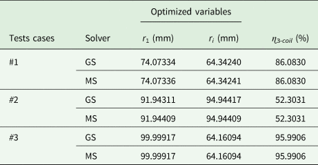
Taking into account the application requirements and bounds described in section “Optimization process”, the results of the optimization process are summarized in Table 1. In particular, the optimal values provided by the optimization process for r 1 and r 3 and the corresponding power transfer efficiency are reported in the table.
Optimized parameters

As can be observed, the optimal values provided by the two solvers (the GS and the MS) are coincident; thus confirming that the achieved maximum value of the efficiency is clearly a global maximum.
5.1. Test case #1
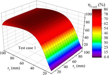
For test case #1, the optimal values of the coil radii r 1 and r 3 are 74.07 and 64.34 mm, respectively.
The 3-D surface representing the ɳ 3-coil as function of r 1 and r 3 is illustrated in Fig. 3. When r 1 and r 3 are set to their optimal values, ɳ 3-coil assumes its maximum equal to about 86% (see Fig. 3). Additionally, from Fig. 3 it can be observed that the efficiency is nearly independent of r 1.
Test case #1: Analytical results of ɳ 3−coil for different values of r 1 and r 3 (z 12 = d, z 13 = z 23 = d/2).

5.2. Test cases #2 and #3
In this subsection, the analytical results obtained by the optimization process for the test cases #2 and #3 are detailed.
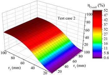
When the relay coil is coplanar to the TX coil (Test case #2), the optimal values of r 1 and r 3 are of about 91.94 and 94.94 mm, respectively (see Table 1, and Fig. 4). The optimal values of r 1 and r 3 correspond to a maximum of the power transfer efficiency of about 52.30%. The efficiency behavior as function of r 1 and r 3 is illustrated in Fig. 4. It can be seen that the efficiency is mainly affected by r 3; in fact, for a given value of r 3 the efficiency is nearly constant.
Test case #2: Analytical results of ɳ 3−coil for different values of r 1 and r 3 when the relay is coplanar to the TX coil (z 12 = d, z 13 = 0, z 23 = d).

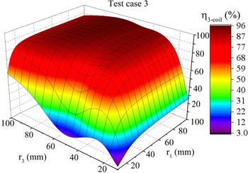
As per the test case #3, the optimal values of r 1 and r 3 are 100 and 64 mm, the corresponding efficiency is 96%. The efficiency as function of r 1 and r 3 is illustrated in Fig. 5; in this case it can be seen that the efficiency exhibits a similar dependence on r 1 and r 3.
Test case #3: Analytical results of ɳ 3-coil for different values of r 1 and r 3 when the relay is coplanar to the RX coil (z 12 = d, z 13 = d, z 23 = 0).

The difference of the realizable maximum power efficiency obtained for the two test cases can be explained as follows. In both the analyzed cases, the relay coil acts as a matching network.
For the Test case #2 where the relay is coplanar to the TX coil, the optimization process allows to minimize the mismatch between the transmitting resonator and the generator impedance R G.
Similarly, for the Test case #3 where the relay is coplanar to the RX coil, the optimization process allows to minimize the mismatch between the receiving resonator and the load impedance R L. However, the efficiency as defined in (12) only depends on R L, while it is independent of R G. In more detail, by using the scattering parameters of the link the efficiency can be expressed as:
 $$\eta _{RF-RF} = \displaystyle{{{\vert {S_{21}} \vert } ^2} \over {1-{\vert {S_{11}} \vert } ^2}}.$$
The above reported equation highlights that, according to the definition commonly adopted in the context of WPT, the efficiency only depends on the mismatch at the output port of the WPT link. This explains the difference between the results achieved for the efficiencies for the test cases #2 and #3.
Accordingly, it can be concluded that when the goal is to maximize the efficiency as defined in (12), or equivalently in (17), the best configuration is the one corresponding to the test case #3. This configuration will be numerically and experimentally analyzed in the following section.
6. Full-wave and circuital simulation results
The optimal configuration of the link corresponding to the test case #3 has been analyzed by means of full-wave simulations performed with CST Microwave Studio (see Fig. 2(d)). A Tower Workstation HP Z230 was used for carrying out the numerical analysis. The machine was equipped with, a i7-4790 CPU @ 3.60 GHz, 16 GB of RAM, an HD of 1 TB, and a graphic board NVIDIA Quadro K620 (GPU with 2 GB dedicated). The operating system installed on the HP Z230 was Microsoft Windows 10 Pro.
The adopted design parameters are summarized in Table 2; the distances between the three coils are: z 12 = z 23 = d = 80 mm, z 13 = 0.
Design parameters of the test case #3

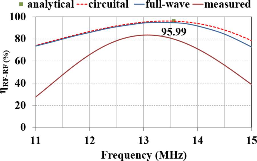
By using the simulated scattering parameters of the link in (17) the results reported in Fig. 6 have been obtained for the efficiency; according to full-wave simulations the maximum of η RF−RF is of about 95% which is very close to the value expected from the theory (i.e. 96%).
Test case #3: comparison of the results achieved by means of the optimization process, circuital, full-wave simulations, and measurements.

Figure 6 also shows the results achieved from circuital simulations. In more detail, simulations have been performed by using the circuital simulator AWR for analyzing the equivalent circuit of the link illustrated in Fig. 1; the values assumed for the parameters are the ones provided by the analytical formulas. From Fig. 6, it can be noticed that a very good agreement has been obtained between full-wave and circuital simulations, thus confirming the accuracy of the values provided by the analytical formulas for the parameters of the link.
In order to give an idea of the advantages of the proposed algorithm, it is worth underlining that the computation of the optimal solution through the optimization of (12) takes few seconds. As per the time required for a full-wave simulation, it depends on the adopted solver. The computation time is of about 1 h with the frequency domain solver, while it is of about a week when the time domain solver is used. Obviously, in order to perform an optimization through full-wave simulations it is necessary to perform several simulations.
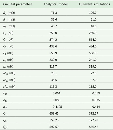
Finally, referring to the equivalent circuit illustrated in Fig. 1, Table 3 compares the values of the parameters provided by the analytical formulas and those extracted from full-wave simulations. It can be observed that they are in an excellent agreement.
Circuital parameters (Test case #3)

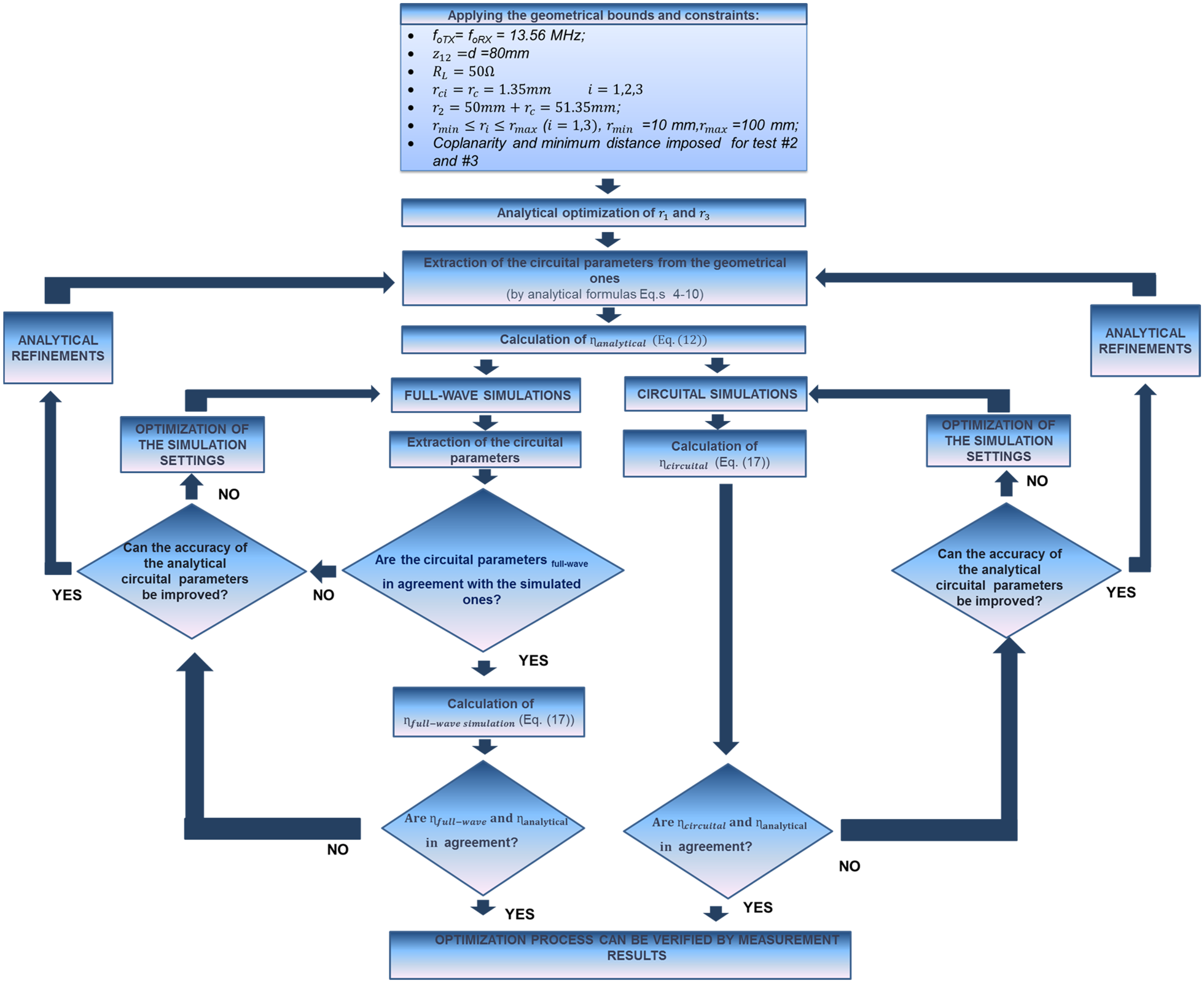
A flowchart describing the optimization process of a WPT link through the proposed algorithm is illustrated in Fig. 7. As it can be seen, by exploiting (12), the optimization of the efficiency with given constraints can be afforded starting from the analytical results and by using full-wave simulations only for verification before fabricating the coils.
Flowchart of the optimization process, circuital, and full-wave simulations.

In the following section, experimental data are reported and discussed.
7. Experimental results
In order to verify the theory, a prototype of a WPT link corresponding to the Test case #3 and having the equivalent parameters given in Table 3 has been fabricated. The geometrical parameters of the coils are the ones summarized in Table 2, while the distance between the transmitting and the receiving resonators is 80 mm.
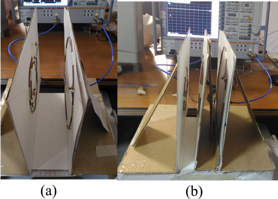
The realized experiment is illustrated in Fig. 8; each resonator has been realized by using a copper cylindrical wire and a series compensating lumped capacitor. Measurements of the scattering parameters were performed by using a R&S ZVA 50 Vector Network Analyzer. By using the discrete values of the lumped capacitors at disposal of the authors, the resonators were optimized in order to be synchronous and to exhibit values of the equivalent parameters (see Fig. 1) as close as possible to the ones reported in Table 3.
Experimental setup adopted for the test case #3 (a) and the re-optimization process of the test case #3 (b). The distance between the transmitting and the receiving resonators is 80 mm.

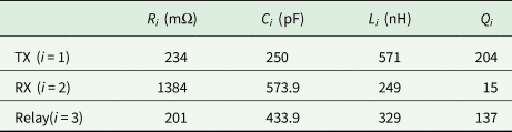
The measured values of the parameters of the coils are summarized in Table 4; the frequency of resonance is 13.32 MHz. By comparing the values of the parameters reported in Table 3 with the ones of Table 4, it is evident that the quality factors of the realized resonators are definitely lower than the ones assumed during the optimization process of the link. Therefore, the realized link exhibits lower values of the efficiency. This is evident from Fig. 6, where the measured efficiency is compared with the results achieved from full-wave simulations and analytical formulas corresponding to the parameters of Table 3: from measurements the maximum of ɳ 3−coil is of about 82.5% and occurs at the frequency of resonance, i.e. 13.32 MHz. The values obtained for the efficiency by using the various approaches are reported in Table 5.
Measured circuital parameters (Test case #3)


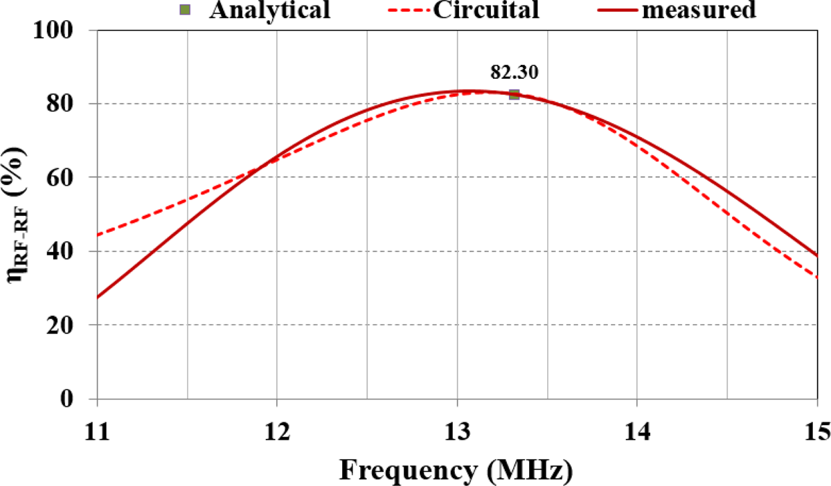
Figure 9 compares the measured efficiency with circuital simulations when the measured parameters summarized in Table 4 are used, the value provided by the analytical formula is also reported; a good agreement can be observed.
Test case #3: Comparison of the results achieved by means of the re-optimization process, circuital, and measurements. For the analytical and circuital results, the measured data reported in Table 4 have been used.

In order to further investigate the performance of the fabricated link, the available and the transducer gain have also been measured. In fact, as already observed, the efficiency as defined in (11) coincides with the power gain of the link and only depends on the output port, i.e. on the load impedance R L. In order to complete the characterization of the link highlighting the behavior also with respect to a generator with impedance R G, two useful figures of merit are the available gain (G A) and the transducer gain (G T) [Reference Mastri, Mongiardo, Monti, Dionigi and Tarricone33].
The available gain allows to evaluate the maximum power that the network is able to deliver to a load for a given generator (i.e. for a given value of R G) and it is independent of R L. The transducer gain allows to evaluate the power that the network is able to deliver to a given load (i.e. to a given R L) for a given generator (i.e. for a given value of R G). In more detail, for given values of R G and R L, G T coincides numerically with the active power delivered to the load for a unitary value of the power supplied by the generator.
According to the above reported observations, G A and G T depend on R G; for the fabricated link, from circuital simulations it has been derived that the optimal value of R G for the fabricated link is about 4 Ω (R Gopt = 3.8 Ω).
Figure 10 shows the measured gains as function of the frequency for R G = 4 Ω and R L = 50 Ω; while, the values calculated for the output voltage are illustrated in Fig. 11. As can be seen, being the value assumed for R G nearly coincident with the optimal one, the three gains are all maximized at the frequency of resonance. In Fig. 12, the output voltage calculated assuming that the link is driven by an AC voltage source having an internal resistance equal to 4 Ω are reported. The results have been calculated through circuital simulations performed by modeling the link as a black-box component described by the measured scattering parameters.
Measured gains of the fabricated link for R G = 4 Ω and R L = 50 Ω. The efficiency η coincides with the power gain of the link.

Output voltage calculated for R L = 50 Ω assuming on the input port a voltage generator (V G = 1 V, see Fig. 1) with internal resistance R G = 4 Ω. The results have been obtained by using the measured scattering parameters of the link in circuital simulations and by varying the frequency of the AC voltage generator.

Measured gains of the fabricated link for R G = 50 Ω and R L = 50 Ω. The efficiency η coincides with the power gain of the link.

Finally, in order to highlight the behavior of G T and G A as function of R G, in Fig. 12 the measured gains for R G = 50 Ω and R L = 50 Ω are reported.
As expected, being the value assumed for R G very different from the optimal one, G A and G T still have a maximum at the frequency of resonance, but this is definitely lower than the absolute maximum value that can be obtained for the two-port network (i.e. about 0.82).
This result is due to the fact that the proposed algorithm optimizes the efficiency defined as the power gain of the link; consequently, the optimization is performed with respect to a given load independently of R G. In this regard, it is worth observing that, this is an intrinsic limitation of the three coils configuration. In fact, as demonstrated in [Reference Mastri, Mongiardo, Monti, Dionigi and Tarricone33], by using a three coil configuration it is possible to maximize either G A or G T, therefore, only a local maximum of G T can be obtained. In order to simultaneously maximize all the three gains a four coil configuration has to be considered [Reference Mastri, Mongiardo, Monti, Tarricone and Costanzo35].
7.1. Re-optimization
The results reported in the previous subsection highlight that, in general, it is difficult to reproduce for all the parameters of the link the exact values assumed during the design process.
In this regard, a possible design procedure could be
(1) optimize the link taking into account the constraints of the specific application of interest;
(2) realize the resonators so to achieve values of the equivalent parameters as much close as possible to the ones obtained from the optimization process;
(3) re-optimize the link by using the measured data of the resonators and by acting on the “free-parameters”.
The last step should be performed taking into account the starting configuration of the link and the constraints imposed by the specific application. For instance, for the Test case #1, once the resonators have been realized, in the case where the achieved parameters are different from the desired ones, a possible solution could be to relax the constraint of equally spaced resonators and to optimize d 1 (or equivalently d 2) for given values of all the other parameters. Similarly, for the Test cases #2 and #3, if compatible with the specific application of interest, a possible strategy could be to relax the constraint on the coplanarity of the relay with the transmitting (Test case #2) or the receiving (Test case #3) resonators.
In particular, for the Test case #3 a possible solution to improve the results achieved for the efficiency of the realized three-coil system consists in relaxing the constraint of having the relay coplanar to the receiving resonator. In particular, similarly to the Test case #1 it could be assumed that the relay is at a distance d 2 from the receiving resonator which can be optimized, while keeping constant all the remaining parameters.
Accordingly, the optimization procedure has been applied with the goal of maximizing the efficiency by acting on d2 with 0 <d2 <d, being d = 80 mm. The optimization was performed by using for the resonators the measured parameters that are reported in Table 4.
The optimal value of d 2 obtained by the re-optimization process is 6 mm; in particular, for d 2 = 6 mm the power transfer efficiency is equal to 82.9%, while the value achieved for d 2 = 0 is 82.3%.
This result has been experimentally verified. In particular, measurements were performed by measuring the scattering parameters of the link by varying d 2; the experimental setup is illustrated in Fig. 8(b).
The results achieved this way for the efficiency are reported in Fig. 13 and are compared with analytical data. As can be noticed, a good agreement has been observed.
Comparison of the results achieved for the link illustrated in Fig. 8b by varying the distance (d 2) between the relay element and the receiving coil.

Measurements confirm that the maximum of the efficiency (ɳ 3−coil = 84.80%) occurs at d 2 = 6 mm.
However, for the analyzed case, the measured data also confirm that the re-optimization process allows obtaining a very slight improvement of the efficiency.
8. Conclusions
In this paper a design procedure for a 3-coil WPT link has been presented.
The proposed approach aims at maximizing the efficiency of the link by optimizing its geometrical parameters for assigned constraints. The case of a link using synchronous resonators each one consisting of a circular loop loaded by a lumped compensating capacitor has been analyzed.
The proposed algorithm exploits the circuital equivalent representation of the link as a two-port network; for the lumped element equivalent circuit, appropriate theoretical formulas relating the equivalent parameters to the geometrical ones have been adopted.
The proposed procedure considerably reduces the computational time with respect to the optimization through full-wave simulations while finding a global reliable solution.
The achievable results are discussed referring to an application constraining the dimensions of the receiving coil, as it happens in most practical cases of interest. For the analyzed example, analytical data are validated through full-wave simulations and measurements.
Acknowledgement
This work was supported by the COST Action IC1301 WiPE Wireless Power Transmission for Sustainable Electronics.
 Giuseppina Monti (M'16-SM'16) received the Laurea degree in telecommunication engineering (with honors) from the University of Bologna, Bologna, Italy, in 2003, and the Ph.D. degree in information engineering from the University of Salento, Lecce, Italy, in 2007. She is currently with the Department of Innovation Engineering, University of Salento, Lecce, Italy, as a Temporary Researcher and Lecturer in CAD of microwave circuits and antennas. Her current research interest includes the analysis and applications of artificial media, the design and realization of microwave components, MEMS-based reconfigurable antennas and devices, rectennas, and systems and devices for wireless power transmission applications. She has coauthored three book chapters and more than 150 papers in international conferences and journals.
 Maria Valeria De Paolis received the M.S. degree in telecommunications engineering (cum laude) from the University of Salento, (Lecce, Italy) in 2014. She obtained the Ph.D. degree in Engineering of Complex Systems at the University of Salento (Lecce, Italy). Her work was focused on the design, characterization, and fabrication of wireless power transfer systems. In November 2017, she was contracted as a Post-Doctoral Researcher in the research laboratory of analysis and architecture of systems (LAAS-CNRS) of Toulouse (France). Her research activity is currently focused on the design and characterization of RF passive sensors.
 Laura Corchia was born in Italy, in 1980. She received the M.S. degree in Telecommunication Engineering and the Ph.D in Information Engineering from University of Salento, Lecce, Italy, in 2007 and 2011, respectively. She is currently a Postdoctoral Researcher with the Department of Engineering for Innovation, University of Salento. Her research interests include the development of near and far field wireless power transfer links and power management units for wearable applications, the design and the fabrication of reconfigurable antennas, and the characterization of antennas and microwave devices.
 Apostolos Georgiadis was born in Thessaloniki, Greece. He received the Ph.D. degree in electrical engineering from the University of Massachusetts, Amherst, in 2002. In March 2007 he joined CTTC, Spain as a senior researcher. In July 2016 he joined Heriot-Watt University, Edinburgh as an Associate Professor. He has been Associate Editor of the IEEE Microwave and Wireless Components Letters and the IET Microwaves, Antennas and Propagation. He co-founded and was Editor-in-Chief of the Cambridge Wireless Power Transfer Journal. He was a Distinguished Lecturer of IEEE Council on RFID. He is an URSI Fellow. He was a co-recipient of the 2016 Bell Labs Prize. His research interests include energy harvesting and wireless power transmission, RFID technology, active and phased array antennas, inkjet and 3D printed electronics, and millimeter wave systems. He has published more than 200 papers in peer reviewed journals and international conferences.
 Luciano Tarricone received the Laurea degree in electronic engineering (cum laude) and Ph.D. degree from Rome University “La Sapienza,” Rome, Italy, in 1989 and 1994. He was a Researcher with the IBM Rome Scientific Centers (1990–92), and with the IBM European Center for Scientific and Engineering Computing (1992–94). He was a Researcher and a Professor with the University of Perugia, Perugia, Italy (1994–2001). Since November 2001, he has been a Faculty Member with the Department of Innovation Engineering, University of Salento, Lecce, Italy, where he is Full Professor of EM Fields and coordinates a research group and the Electromagnetic Lab. He has authored and coauthored approximately 400 scientific papers and several books. His main contributions are in bioelectromagnetics, numerical methods for efficient CAD of microwave circuits and antennas, electromagnetic energy harvesting and wireless power transmission, novel CAD tools and procedures for microwave circuits, RFID, and EM highperformance computing.