



Introduction
The two frequency bands that can be extensively used in the implementation of 5G communication systems are the sub-6 GHz region and the millimeter-wave band [1]. In the era of 5G systems, fundamental technologies such as multiple-input–multiple-output (MIMO), beamforming, cognitive radio (CR), and edge computing play a crucial role [Reference Nordrum and Clark2]. The usage of MIMO technology instead of conventional single-input–single-output systems is an effective choice to achieve high data rates [Reference Sharawi3]. In the past, various works have been done on MIMO antennas for achieving enhanced gain, impedance bandwidth as well as isolation among the different ports of the MIMO [Reference Peng, Zhi, Yang, Cai, Wan and Liu4–Reference Kumar, Babu, Narayan and Raju6]. The CR technology provides better spectrum utilization [Reference Mitola and Maguire7]. In any CR system, there are typically two types of users: primary users (PUs) who hold a license and secondary users (SUs) who do not possess a license. The operations performed by CR are subcategorized as (i) spectrum interweave CR and (ii) spectrum underlay CR. For the interweave CR system, an ultrawideband (UWB) or wideband (WB) antenna acts as a sensing antenna that senses or scans the whole frequency band of interest and identifies the unused portion of the spectrum by the PU. To facilitate communication with the SU and grant them access to utilize the unused spectrum, a narrowband communication antenna is necessary. In the underlay system, both SU and PU can simultaneously access the spectrum, but the signal-to-interference plus noise ratio value of the SU must be below the allowed standard value. The SU must operate in a manner that does not interfere with the PU. If interference occurs, it is imperative to stop the communication of the SU promptly. Therefore, for underlay systems, the UWB or WB sensing antenna should have reconfigurable band-notch characteristics for the communication of SU [Reference Tawk, Costantine and Christodoulou8]. In the literature, very few designs were available that work in all the modes of CR, i.e., interweave CR and underlay CR. The design presented in paper [Reference Hussain and Sharawi9] works for the interweave CR only and no discussion on underlay operation was given. In paper [Reference Thummaluru and Chaudhary10], all the CR operations can be performed simultaneously by all ports but, isolation between the ports was enhanced by using reflectors, so due to extra reflectors overall physical size of the design was increased. The problem of low isolation was improved in paper [Reference Alam, Thummaluru and Chaudhary11] by properly orienting the ports and placing them at an appropriate distance from each other. But at the same time, the tunability range was reduced for interweave and underlay CR systems. To minimize the abovementioned isolation problem, in paper [Reference Alam, Thummaluru and Chaudhary12], the authors added two separate ports which further improved the tuning range of the communicating antennas.
All the abovementioned designs were based on microstrip radiators integrated with CR-MIMO functionalities. The main drawback of using a microstrip radiator was low isolation among the ports in specified impedance bandwidth and lower gain after integrating lumped elements like PIN diodes, varactor diodes, etc. Additionally, it is crucial to note that in all the aforementioned designs, circularly polarized (CP) behavior was not explored. CP should be thoroughly investigated and considered in the design process for a comprehensive approach to wireless communication. Therefore, in this research, the proposed antenna is founded on a dielectric resonator (DR) as the primary radiator. The drawbacks listed above could be removed using a dielectric resonator antenna (DRA) integrated with MIMO-CR functionality. In the proposed design, appropriate orientation, and spacing of the antenna elements have been chosen which improved the isolation. To obtain wide impedance as well as CP (<3 dB) bandwidth, a modified C-shaped aperture is taken. Finally, the antenna is integrated with a reconfigurable multipurpose filter and this same proposed structure works for both interweave and underlay showing gain in the range from 3.13to 5.19 dBic.
The workflow of this paper is discussed as follows: The “Two-port WB CP-MIMO antenna design” section describes the design of a single-port-modified C-shaped aperture-fed antenna supporting a frequency range of 3.8–5.05 GHz. Single-port antenna is then extended to a two-port MIMO antenna with 90° rotated elements for better isolation among ports and then its WB CP behavioral analysis is discussed; In the “Design of multifunctional filter” section, a multipurpose reconfigurable filter showing all-pass, band-pass, and band-reject filtering characteristics for CR applications is presented; Further, in the “CP-MIMO antenna and multifunctional filter integration” section, integration of the CP-MIMO antenna with multipurpose reconfigurable filter is depicted; the simulated results are then compared with the measured ones as well as comparison of the proposed work with the other state-of-the-art designs are presented in the “Measurement outcomes” section; finally, the “Conclusion” section concludes the paper.
Two-port WB CP-MIMO antenna design
In this section, the various design steps of a two-port WB CP-MIMO antenna, covering the frequency range from 3.8 to 5.05 GHz within the sub-6 GHz band, are discussed. Figure 1 shows the single-element, dual-port MIMO antenna and proposed reconfigurable CP-MIMO antenna. The presented structure is simulated and analyzed in Ansys HFSS EM simulation software. Initially, a single-port antenna is designed, which involves three steps as shown in Fig. 2. The evaluation of the single-port antenna is discussed in Fig. 2. The optimized dimension is mentioned in Table 1. It shows that Antenna-I is a simple ring slot aperture-coupled fed DRA. In Antenna II, the shape of the aperture remains the same, but the feeding line is altered by incorporating a circular ring at one of the edges of the feedline. Finally, in Antenna III, the circular ring-shaped aperture is further modified while keeping the rest of the antenna structure unchanged, as shown in Fig. 2(c). When we feed the DR-based antenna with a modified C-shaped aperture, then HEM12δ mode is generated inside the ceramic at 5 GHz. This is because the C-shaped aperture, i.e., feeding structure behaves as a magnetic dipole [Reference Sharma, Das, Gupta and Gangwar13]. The resonant frequency associated with the HEM12δ mode can be predicted through HEM11δ mode. The empirical formula of HEM11δ mode can be calculated using the following equation [Reference Sharma, Das and Gangwar14]:
 \begin{equation}{{\text{f}}_{r,HEM11\delta }} = \frac{{18.972 \times {{10}^8}}}{{2{{\pi D}}\sqrt {{\varepsilon _{alumina}}} }}\left\{ {0.27 + 0.36\left( {\frac{{\text{D}}}{{2{\text{h}}}}} \right) + 0.02{{\left( {\frac{{\text{D}}}{{2{\text{h}}}}} \right)}^2}} \right\}{\text{ }}\end{equation}
 \begin{equation}{{\text{f}}_{r,HEM12\delta }} = 1.3 \times {{\text{f}}_{r,HEM11\delta }}\,\,\,\,\,\,\,\,\,\,\,\,\end{equation}
Geometrical layout of designed MIMO antenna. (a) Top view of single element CP DRA, (b) Perspective view of single-element CP DRA, (c) 2-port CP-MIMO DRA, and (d) Proposed reconfigurable CP-MIMO DRA.

Schematic of different antenna configurations. (a) Antenna I, (b) Antenna II, and (c) Antenna III.

Optimized parameters of the proposed filtenna (unit in mm)

The S-parameters and axial ratio curves for all three antenna configurations are depicted in Fig. 3(a) and (b). From Fig. 3(a), it can be said that the maximum impedance bandwidth is achieved in the case of Antenna-III, i.e., 3.8–5.05 GHz. From Fig. 3(b), it can be observed that Antenna-I shows linear polarization characteristics. For the Antenna II configuration, the addition of a circular ring in the feedline serves to further decrease the axial ratio value, though it remains above the 3 dB standard. Therefore, the aperture slot undergoes more modifications, resulting in the Antenna III configuration. By applying modifications in the aperture, orthogonal field components are generated with a phase difference among them creating a wide circular polarization bandwidth. This can be visualized by the electric field (E-field) distribution over the DR. Figure 4(a) and (b) shows the field distribution at ωt = 0° and 90°. It is confirmed from the field distribution that the E-field vector is moving orthogonally at 4.9 GHz. It confirms the CP behavior of the proposed antenna. The modal field variation in the DRA is shown in Fig. 4(c). It shows that the proposed antenna works in HEM12δ mode. Finally, the two-port MIMO structure is formed by placing the elements anti-parallelly (180° rotated) and giving appropriate spacing between them. This antenna arrangement is shown in Fig. 1(c). The S-parameters of the presented structure are displayed in Fig. 5. In this two-port MIMO design, the ground planes of the two elements are interconnected using a thin metal strip, an essential requirement for a MIMO structure [Reference Sharawi15]. The two-port MIMO configuration produces good impedance matching giving WB response from 3.8 to 5.05 GHz, which is the same as single-port antenna. The presented structure demonstrates excellent isolation performance, showing values below 28.5 dB. In the MIMO configuration, an overlapping axial ratio bandwidth of 40% is achieved. The optimized parameters of the proposed structure are depicted in Table 1.
Results of Antenna-I, -II, and -III. (a) Reflection coefficient and (b) Axial ratio.

E-field distribution at 4.9 GHz for (a) ωt = 0°, (b) ωt = 90°, and (c) HEM12δ mode.

S-parameter variation of the dual-port antenna.

Design of multifunctional filter
As it is known, integrating CR capabilities with the MIMO antenna system requires achieving both sensing and communicating functions from a single port. This can be done by introducing a reconfigurable multifunctional filter within the feed line of the antenna elements. If a simple microstrip line is designed then it serves as an all-pass filter [Reference Alam, Thummaluru and Chaudhary11]. From various literature, it was observed that split ring resonator (SRR) structures work as bandpass filters [Reference Zhou, Tong, Fu and Wu16]. Figure 6(a) and (b) shows the circular SRR structure added to the feed line and its S-parameter variation. From Fig. 6, it can be seen that the feed line integrated circular SRR structure shows bandpass behavior within the sensing range of 3.8–5.05 GHz. For designing the SRR, the following equation is used [Reference Sehgal and Patel17]:
 \begin{align}{f_r} & =\nonumber \\ & \,\, \frac{1}{{2\pi \sqrt {0.0002\,L\,\left( {2.303\,lo{g_{10}}\frac{{4L}}{{{h_s}}} - 2.451} \right)\left[ {\,\frac{{\left( {3\,{R_{avg}} - g} \right){C_{Pul}}}}{2} + \,\frac{{{\varepsilon _s}{h_s}d}}{{2g}}} \right]} }}\end{align}
Filter design and its results. (a) Layout of multipurpose filter; (b) S-parameter of circular SRR, reflection coefficient in case of (c) all-pass filter and (d) band-reject filter.

The parameters described in the equation are as follows: R avg, which shows the average value of the two designed split rings; g, indicating the spacing or gap; C pul, showing the capacitance per unit length; L, calculated as L = 6 * n – g, where n is a given parameter; and d represents the spacing between the inner and outer ring. Figure 6(c) shows the reflection coefficient of the multifunctional filter after applying the five PIN diodes (D1, D2, D3, D4, D5). In the proposed filter design, when all the diodes are ON, then it behaves as all pass filter. In case, when all the diodes are OFF, then the filter acts as a band pass filter. In case, when D1, D4, and D5 are ON, and D2 and D3 are OFF, it behaves as a band notch filter, whose S-parameters are depicted in Fig. 6(d).
CP-MIMO antenna and multifunctional filter integration
In this section, the discussion revolves around a multifunctional reconfigurable filter that is integrated with the two-port CP-MIMO DR-based WB antenna. This seamless integration is effortlessly achieved with minimal matching losses, primarily because both the antenna and filter feedlines are maintained at the same dimensions. The overall structure of the proposed two-port CP-MIMO antenna with integrated CR is depicted in Fig. 1(c). Figure 7 shows the reflection coefficient curve of the proposed MIMO antenna when all the diodes are OFF. From Fig. 7, it can be said that the designed antenna works between 3.8 and 5.05 GHz, in case of all diodes are OFF. The radiator is used for sensing purposes. Only a single port is analyzed in this context, given that the design is symmetrical and the same antenna elements are used for the two-port structure. Therefore, similar results will be obtained for both ports. Figure 8(a) and (b) shows the input reflection coefficient variation with different values of reverse bias voltages of the varactor diode in two different scenarios. In case I, all the PIN diodes are OFF, while in case II, D1, D4, and D5 are ON, and D2 and D3 are OFF. From Fig. 8(a), the passband is reconfigured to a higher frequency with an increase in reverse bias voltage. From Fig. 8(b) it can be observed that increasing the reverse bias voltage results in the reconfiguration of band rejection to a higher frequency. In Case I, the antenna operates for CR interweave, whereas in Case II, it works as CR underlay.
Reflection coefficient curve of MIMO antenna when all the PIN diode OFF (sensing case).

Reflection coefficient plot with alteration in reverse bias voltage across varactor diode. (a) Interweave case and (b) Underlay case.

Measurement outcomes
The fabricated prototype of the proposed two-port CP-MIMO antenna with CR feature is shown in Fig. 9. To validate the simulated outcomes, measurements were conducted on the fabricated antenna, and a comparison was made between the simulated and measured results. The S-parameters of the proposed antenna is measured using Agilent VNA E5071C. The simulated and measured S-parameter curve for all three operations of CR are shown in Fig. 10(a–d). It is visible from the graph that there is a slight variation in the measured and simulated outcomes. This could be possibly due to the adhesive used between the ceramic resonator and the FR4 substrate. The use of biasing lines could also be the reason for the same. The proposed antenna can efficiently perform sensing operations in the spectrum 3.8–5.05 GHz. Through appropriate biasing of lumped elements, specifically varactor diodes and PIN diodes, tunability is realized for interweave operation ranging from 3.8 to 4.3 GHz. Conversely, for the underlay mode, the tunable range covers from 3.8 to 4.5 GHz.
Pictures of fabricated antenna. (a) Top view and (b) Bottom view.

S-parameter variation of CP-MIMO DRA (a) |S11| in sensing mode (b) |S21| in sensing mode (c) Interweave mode when V r = 3 V (d) Underlay mode when V r = 3 V.

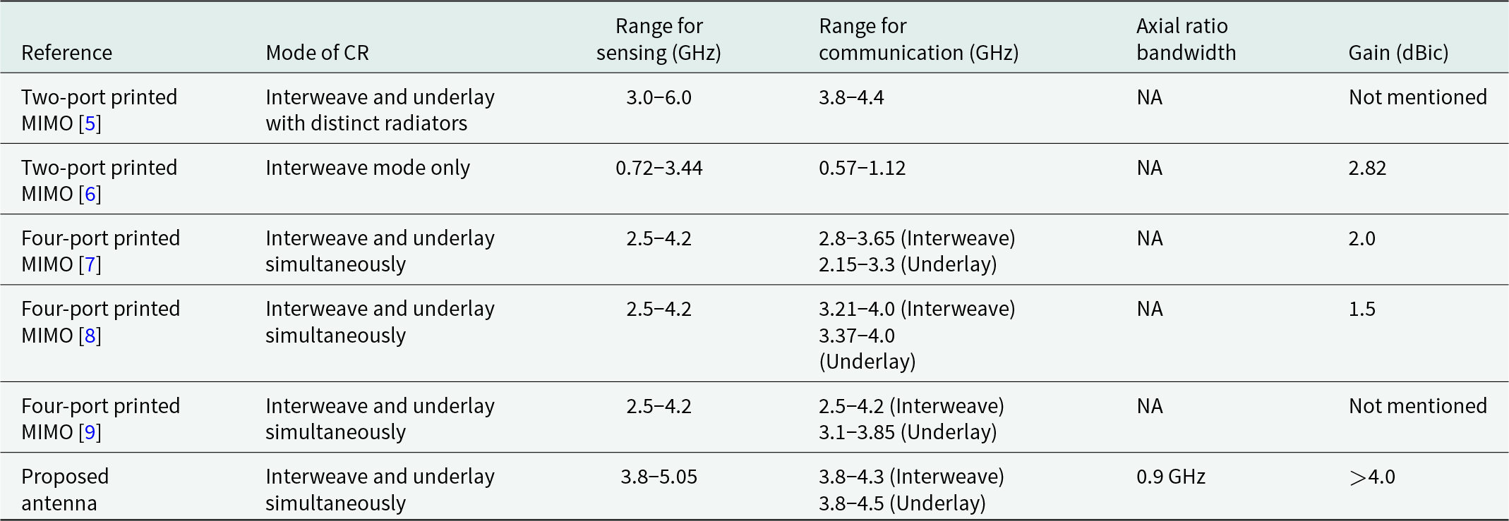
The axial ratio and gain of the presented geometry are displayed in Fig. 11. The axial ratio spans from 3.6 to 4.5 GHz. Also, the measured gain is above 4.0 dBic at the operating frequency band. The calculated radiation efficiency is displayed in Fig. 11(b). It shows more than 80% of radiation efficiency at the working frequency band. Figure 12 measured and simulated left-handed circular polarization (LHPC) and right-hand circular polarization (RHCP) radiation patterns at 4.0 GHz with port-1 and port-2, respectively. From Fig. 12, it is observed that the radiation pattern is broadsided with both the antenna ports, which confirms the HEM12δ mode inside the cylindrical ceramic. The designed radiator shows LHCP features because LHCP is more dominant as compared to RHCP. Table 2 compares the performance of the designed CP dual-port MIMO DRA for CR applications with other existing MIMO antennas for CR applications. From Table 2, it can be observed that the designed structure has two major advantages over the other designed one: (i) WB CP feature is achieved in sensing mode, which has not been discussed till now for CR applications and (ii) gain value is high as compare to other existing printed MIMO antenna for CR application.
Far-field parameters of the proposed radiator. (a) Gain, (b) Radiation efficiency, and (c) Axial ratio.

Measured and simulated LHCP and RHCP pattern at 4.0 GHz. (a) Port-1 and (b) Port-2.

Performance comparison of proposed MIMO radiator with other existing MIMO radiators for CR applications
Further, to analyze the MIMO behavior of the proposed antenna, the envelope correlation coefficient (ECC) and diversity gain (DG) have been listed in Table 3. By observing the values of ECC and DG, it can be said that the ECC value is well below the standard acceptable limit of 0.5 in the whole sensing band which signifies better MIMO behavior. Further, the DG of the proposed antenna is around 10 dB within the sensing range again validating better MIMO performance.
Calculated values of ECC and DG of designed MIMO antenna

Conclusion
In this work, a two-port CP-MIMO DRA for 5G-CR applications is designed and analyzed. DR is used as a radiator, for getting two important advantages: (i) isolation improvement (>25 dB) without using any separate structure; and (ii) improved gain (>5.0 dBic) performance in the presence of active elements like diodes. The proposed antenna performs sensing from 3.8 to 5.05 GHz. For communication under interweave CR mode, the bandpass reconfigurability spans from 3.2 to 4.3 GHz. For spectrum underlay, the band reject operation demonstrates tunability ranging from 3.1 to 4.5 GHz. The proposed two-port antenna shows an overlapping axial ratio BW of 40% in the desired frequency range. The proposed two ports MIMO antenna can work efficiently for the midband 5G-CR systems.
Funding statement
This research received no specific grant from any funding agency, commercial or not-for-profit sectors.
Competing interests
The authors report no conflict of interest.

Yajush Rai born in Varanasi, Uttar Pradesh, India, in 1993. He is a research scholar in the Electronics and Communication Engineering Department at Motilal Nehru National Institute of Technology Allahabad, Uttar Pradesh, India. He is completed his Master’s degree (M.Tech) in Electronics and Communication Engineering from University of Allahabad, India, in 2020 and Bachelor’s degree in Electronics and Communication Engineering from Raj Kumar Goel Institute of Technology (R.K.G.I.T), Ghaziabad, India, in 2017. His research interests include dielectric resonator (DR)-based antenna designs for sub-6 GHz 5G application, DR-based filtennas for cognitive radio applications, and antennas for imaging and sensing.

Deepak Sigroha earned his degree of Bachelor of Technology from Maharshi Dayanand University Rohtak, Haryana, India, in 2011, and later completed his Master of Technology in Signal Processing at the Indian Institute of Technology Guwahati, Assam, India, in 2014. Following this, he joined Sant Longowal Institute of Engineering and Technology (Deemed-to-be-university, under Ministry of Education, Govt. of India), Longowal, Punjab, India, as an Assistant Professor in the Electronics Engineering Department. He served in this capacity until December 2017. Presently, he holds the position of Assistant Professor in the Department of Electronics Engineering at Rajkiya Engineering College Sonbhadra, Uttar Pradesh, India. Deepak Sigroha has contributed to the field with two publications in International Journals (SCI Indexed) and has presented three articles in National/International Conferences. His research focus encompasses various areas, including VLSI, biomedical signal processing, MIMO antennas, antennas for IoT applications, circularly polarized DRAs, ultrawideband and super wideband antennas, wearable antennas, and antenna optimization using machine learning.

Krishna Tyagi born in Agra, Uttar Pradesh,India, in 1998. She is a junior research fellow in the Electronics and communication Engineering Department at Motilal Nehru National Institute of Technology Allahabad, Uttar Pradesh, India, in 2017. She has completed her Master’s degree (M.Tech.) in Microwave Electronics from Department of Electronic Science, Delhi University South Campus, New Delhi, India, in 2020 and Bachelor’s degree in Electronics and Communication Engineering from U.I.E.T, CSJM University, Kanpur, India. Her research interests include DRA-based antenna design for 5G application, mm–wave-based transreceiver, RFID, and microwave filters.

Gourab Das born in Radhamohanpur, West Bengal, India, in 1990. He completed his B.Tech in Electronics and Communication Engineering from West Bengal University of Technology, Kolkata, India, in 2012 and M.Tech in ECE from Indian Institute of Technology (Indian School of Mines), Dhanbad, India. He has done his Ph.D from Indian Institute of Technology (Indian School of Mines), Dhanbad, India in 2020. Currently, Dr. Das is working as an Assistant Professor in the Department of Electronics and Communication Engineering at Punjab Engineering College (Deemed to be University) Chandigarh. Before joining PEC Chandigarh, He has worked as a postdoctoral Fellow at IIT Kanpur. He has authored or coauthored over 50 research papers in international/national journals/conference proceedings. He has received Best Research Publication Award- 2019 organized by Electronics Engineering Department of IIT (ISM) Dhanbad. His research interests include dielectric resonator antenna, antenna array, and MIMO antenna.

Anand Sharma obtained his Bachelor of Technology from Dr. A.P.J. Abdul Kalam Technical University (AKTU) in 2012, Master of Technology from Jaypee University of Engineering and Technology Guna in 2014, and Ph.D. in RF and Microwave from Indian Institute of Technology (ISM), Dhanbad, in 2018. After that, he joined Government Engineering College Sonbhadra, Uttar Pradesh, India, as an Assistant Professor in Electronics Engineering Department and left the college in June 2019. Currently, he holds the position of Assistant Professor in the Department of Electronics and Communication Engineering, Motilal Nehru National Institute of Technology Allahabad, Prayagraj, Uttar Pradesh, India. He has published more than 60 articles in the International Journal (SCI Indexed) and also presented more than 40 articles in National/International Conferences. His area of research includes MIMO antennas, antenna for IoT applications, circularly polarized DRAs, ultrawideband and super wideband antennas, wearable antennas, and antenna optimization using machine learning.



