
Introduction
The field of capillary suspensions is fairly young but has already gained worldwide attention.[Reference Koos and Willenbacher1–Reference Danov, Georgiev, Kralchevsky, Radulova, Gurkov, Stoyanov and Pelan7] This rapidly growing field has shown significant promise in easily creating adaptable pastes to use in a large variety of applications, e.g., heat-stable and low-calorie chocolate spreads,[Reference Hoffmann, Koos and Willenbacher8, Reference Wollgarten, Yuce, Koos and Willenbacher9] battery slurries,[Reference Bitsch, Dittmann, Schmitt, Scharfer, Schabel and Willenbacher10, Reference Bitsch, Gallasch, Schroeder, Börner, Winter and Willenbacher11] highly conductive pastes for solar cells,[Reference Schneider, Koos and Willenbacher12, Reference Schneider, Maurath, Fischer, Weiß, Willenbacher and Koos13] stable slurries for biofuels,[Reference Jampolski, Sänger, Jakobs, Guthausen, Kolb and Willenbacher14] and strong highly porous ceramics.[Reference Koos, Dittmann and Willenbacher15–Reference Dittmann, Maurath, Bitsch and Willenbacher17] These different applications illustrate the manifold applicability of capillary suspensions due to the easy way capillary suspensions can be adapted to each desired product. It is important to understand the physical phenomenon of capillary forces to understand how the suspensions can be tuned appropriately to create tailor-made materials.
Different particulate networks can be realized when creating capillary suspensions. These differences primarily originate from the wettability of the secondary fluid against the particles, quantified using the three-phase contact angle θ. In the first investigation by Koos and Willenbacher,[Reference Koos and Willenbacher1] two states were defined. For θ < 90°, the secondary fluid preferentially wets the particles and the system is arranged in the pendular state. The particles are directly connected to each other through pendular bridges, a sample-spanning network is formed. The particulate system is in the capillary state when the contact angle θ > 90°. Here, clusters of particles surrounding secondary fluid droplets are formed.[Reference Koos and Willenbacher18] A sample-spanning network is formed in this system through the connections between these polytetrahedral or higher order clusters.
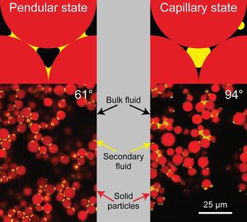
These different network structures were first imaged by Bossler and Koos,[Reference Bossler and Koos19] and are shown in Fig. 1 together with a schematic illustration of the two states. They used a system containing fluorescently labeled silica microspheres ( $d_{50} = 6.4{\kern 1pt} {\kern 1pt} {\rm \mu m}$) dispersed in a mixture of Hexamoll DINCH and n-dodecane with fluorescently dyed aqueous glycerol as the secondary fluid.[Reference Bossler and Koos19] Two different microstructures are visible depending on the surface treatment of the particles, given by the three-phase contact angle θ. The drops in the pendular state have a narrow volume distribution between 2% and 5% of the average particle volume. In the capillary state, the drop sizes have a much wider distribution, ranging from the small, singly connected drops on the particle surface to larger drops connecting many particles. In both cases, a clear sample-spanning network is visible. Various types of structured materials can be created if the structure of this sample-spanning network is preserved.
Schematic illustration and confocal images of capillary suspensions with silica spheres (d 50,3 = 6.40 ± 0.02 µm) that are fluorescently dyed with rhodamine B isothyocyanate (shown in red). Their contact angle was chemically modified before sample preparation. A mixture of Hexamoll DINCH and n-dodecane was used as a bulk phase, and fluorescently dyed aqueous glycerol (yellow) was used as the secondary fluid. On the left side, the particulate network in the suspension is arranged in the pendular state with a contact angle of 61° and the system on the right side is in the capillary state with 94°. Images reprinted with permission from Bossler and Koos.[Reference Bossler and Koos19] Copyright 2016 American Chemical Society (https://pubs.acs.org/doi/abs/10.1021%2Facs.langmuir.5b04246).

New materials by solidification of capillary bridges
The first class of materials is created by preserving the capillary bridges connecting particles through bridge solidification. This can be accomplished through gelation or crystallization of the bridging fluid, or by carrying out a chemical reaction, e.g., polymerization, within the fluid. The structure of these materials should be closely related to the structure of the capillary suspension precursor.
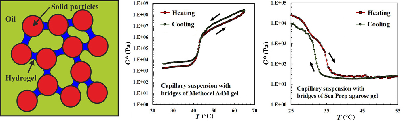
Using systems with a hydrogel bridging fluid, Das et al. recently showed that the properties of the capillary suspensions could be reversibly controlled.[Reference Das, Dunstan, Stoyanov, Starck and Paunov20] Aqueous solutions with hydrogel-forming polymers (Methocel A4M and SeaPrep agarose) were used as the immiscible secondary phase binding together pre-hydrophobized calcium carbonate particles in silicone oil, as shown in Fig. 2. For both secondary phase compositions, they observed the reproducible reaction of the capillary suspension upon external thermal changes using rheological measurements.
(left) Scheme for capillary suspensions made of pre-hydrophobized calcium carbonate in silicone oil with a hydrogel-forming secondary phase. (right) Complex shear modulus as a function of sample temperature. Reprinted with permission from Das et al.[Reference Das, Dunstan, Stoyanov, Starck and Paunov20] Copyright 2017 American Chemical Society.

The gelation of the secondary fluid bridges could be accomplished by either raising or lowering the sample temperature.[Reference Das, Dunstan, Stoyanov, Starck and Paunov20] Samples with aqueous Methocel A4M gelled at higher temperatures and an increase in the complex shear modulus by several orders of magnitude was observed for the capillary suspension. The reverse effect was observed using Sea Prep agarose, where the complex shear modulus decreases with increasing temperature. In both cases, a hysteresis was observed at heating and cooling rates of 1 °C/min or faster, but the effect was highly reproducible. These thermally responsive capillary suspensions could potentially be used in personal care or home products.
Domenech and Velankar used a multiphase solution consisting of silica particles in a bulk polyisobutylene (PIB,  $M_{\rm w} \, \sim \; 2200 \,{\rm g/mol}$) with small amounts of added polyethylene oxide (PEO,
 $M_{\rm w} \, \sim \; 20,{\rm 000} \, {\rm g/mol}$).[Reference Domenech and Velankar2] The system was mixed at an elevated temperature of 80 °C, above the melting temperature of the PEO, and then were rapidly cooled to 5 °C whereupon the bridges would crystallize. This system was used to study the structure of the capillary bridges and morphologic changes with the addition of increasing amounts of secondary fluid.[Reference Domenech and Velankar2, Reference Domenech and Velankar21] In several papers, Velankar and coworkers described the various morphologic changes that were possible in this system and even described bicontinuous structures when larger amounts of secondary fluid are added and the interface becomes jammed by the particles.[Reference Yang and Velankar3, Reference Domenech and Velankar6, Reference Heidlebaugh, Domenech, Iasella and Velankar22–Reference Yang, Roell, Echavarria and Velankar24] Velankar and coworkers used this system primarily to investigate the structure, removing the liquid PIB from the solidified structure-produced solid bodies. Presumably, this method can be used to design porous materials.
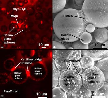
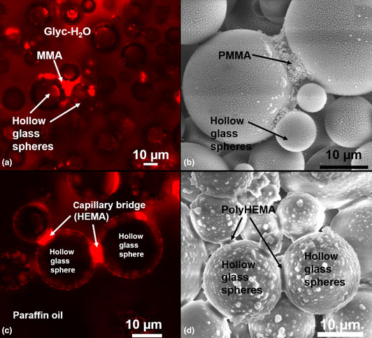
Hauf et al. proved that direct polymerization within the capillary bridges can be used to control the physical and chemical properties of the bridges to create porous materials.[Reference Hauf, Riazi, Willenbacher and Koos25] They primarily used two material systems made of micron-sized hollow glass spheres with monomers as the secondary phases. One system was hydrophobic glass spheres dispersed in water and methyl methacrylate (MMA) as the bridging fluid, as shown in Fig. 3(a). The other system was made of hydrophilic glass hollow spheres in low-viscosity paraffin oil as bulk fluid and hydroxyethylmethacrylate (HEMA) as secondary fluid, as shown in Fig. 3(c). The capillary bridges, which are shown in red, keep their shape after polymerization. The corresponding polymerized porous bodies, without any remaining bulk fluid, are imaged using ESEM as shown in Fig. 3(b) and in Fig. 3(d), respectively. Hauf et al. determined that it is possible to polymerize the capillary bridges in the wet state, at moderate temperatures below 100 °C, without losing volume and by preserving the structure of the material.[Reference Hauf, Riazi, Willenbacher and Koos25] Therefore, the volume and the shape of the capillary/polymeric bridges can be controlled from the wet to the solid state.
(a) Confocal image slice for capillary suspensions made of 40 vol% hydrophobic hollow glass spheres in a glycerin/water mixture (61/39 wt%) with 6 vol% added MMA. The MMA is dyed (red), and the other components are undyed. (b) Corresponding ESEM images of a fractured section of the porous body and the polymeric bridges. (c) Confocal image slice for the 40 vol% hydrophilic hollow glass spheres in paraffin oil with 4 vol% added HEMA. The HEMA here is dyed (red), and the other components are undyed. (d) Corresponding porous solid samples with visible poly(HEMA)-bridges, which interconnect the particles. The samples were polymerized in the bulk fluid for 2.5 h at 82 °C, and the BPO content was 15 mg/mL.[Reference Hauf, Riazi, Willenbacher and Koos25] The samples in paraffin oil were washed in diethyl ether and soaked on paper towels after polymerization. Figure adapted from Hauf et al.,[Reference Hauf, Riazi, Willenbacher and Koos25] reprinted with permission from Springer (Colloid and Polymer Science), copyright 2017.

By varying the initiator concentration during the radical bulk polymerization process, it is possible to control the molecular weight of the polymeric bridges and thus to tune the properties of the final material.[Reference Hauf, Riazi, Willenbacher and Koos25] Porosities of  $\varepsilon _{{\rm open}} = 65\% $ were reached for samples that are made of 30 vol% hydrophilic glass spheres with 6 vol% HEMA. These samples have a failure strength under four-point-bending of 0.1 MPa. For the other material system, made of 30 vol% hydrophobic glass spheres with 6 vol% MMA, the porosity was
 $\varepsilon _{{\rm open}} = 60\% $ and the failure strength was 0.05 MPa. Hauf et al. also demonstrated that this process can be used with other particles or other combinations of particles.[Reference Hauf, Riazi, Willenbacher and Koos25]
Roh et al. have recently shown the application of capillary suspensions to form complex and flexible structures by using the elastomeric polydimethylsiloxane (PDMS), which has important implications for biomedical applications.[Reference Roh, Parekh, Bharti, Stoyanov and Velev26] In this study, the capillary suspensions contained 50% (v/v) precured PDMS microbeads dispersed in water and 10–40 vol% uncured liquid PDMS as the bridging fluid. The suspensions had paste-like behavior and could be three-dimensional (3D) printed in several structures in air and under water. They were then heat-cured at 85 °C to crosslink the liquid silicone bridges between the microbeads, which lead to solidified 3D shapes.[Reference Roh, Parekh, Bharti, Stoyanov and Velev26] The rheological behavior of these capillary suspensions showed an increase in yield stresses and storage moduli, but a reduction as the amount of PDMS increased above 20 vol%. The cured 3D structures showed increasing tensile strength flexibility with increasing amounts of the secondary phase, up to 0.9 MPa at a strain of 1.4 for samples with 30% secondary phase. Depending on the amount of secondary phase, the porosity and the mechanical properties could be controlled, which is useful for creating self-supporting, highly extensive and elastic bodies. These structures feature shape memory effects. An example was shown by bringing a water droplet in contact with a printed mesh, the structure wraps around the droplet and keeps it like a grid-like shell. The biocompatibility of the silicone-based pastes is advantageous for 3D printed biomedical products, or in the field of tissue engineering such as direct printing of bio-scaffolds.[Reference Roh, Parekh, Bharti, Stoyanov and Velev26]
Precursor for sintered materials
A similar way to use capillary suspensions as precursors to create porous materials with beneficial properties is to use them for producing highly porous and strong ceramic bodies with pore sizes <10 µm and porosities >50%. Dittmann et al. investigated a processing route for tailor-made macroporous ceramics by sintering green bodies made of capillary suspensions following debinding of the bulk phase.[Reference Dittmann, Koos and Willenbacher27] Therefore, a particulate system with 15–20 vol% raw ceramic powder, made of calcined α-Al2O3, dispersed in paraffin oil and a water sucrose solution was used as a secondary phase with a varying amount of 0–4 vol%. The water sucrose solution is important because the removal of the bulk phase and water during the debinding process leads to a network collapse if a stabilizing agent is not used. The sucrose crystalizes, and therefore, preserves the structure. Another alternative is to use paraffin wax as the bulk fluid, which also creates a processable paste that is ideal for extrusion and provides an adequate shape accuracy of the porous bodies. The capillary suspensions showed an increase in yield stress with higher particle fractions and with increasing amount of secondary phase over several decades up to 200 Pa. Dittmann and coworkers determined that with the addition of only small fractions of the bridging fluid, from 0 to 1 vol%, the rheological behavior changes dramatically. With more secondary phase, the yield stress reaches a plateau. The amount of secondary fluid also affects the material properties of the sintered bodies. Increasing amounts of secondary phase increase the porosity from 50% to almost 65%. This was also observed in the average pore size of the porous media. The pore sizes are larger for higher porosity samples, but their distribution increases, which means a heterogeneous pore network.[Reference Dittmann, Koos and Willenbacher27] Increasing particle fractions naturally lead to a decrease in the porosity. These porous bodies are interesting for the rapid production of porous ceramics that can be used as lightweight building materials or filter membranes and in applications such as catalytic carriers.
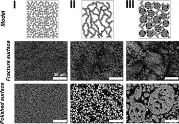
Further microstructural investigations of these macro-porous ceramic materials were completed by Dittmann and Willenbacher, with special attention to the influence of the induced structural properties on the mechanical performance, as shown in Fig. 4.[Reference Dittmann and Willenbacher16] The structure of these materials can be controlled using the amount of the secondary phase from the van der Waals particle network in regime I at 0.0 vol%, to a homogeneous flocculated and sample-spanning pendular state particle network stabilized with capillary liquid bridges in regime II at 2.5 vol%, and finally to strong aggregation and inhomogeneous structure formation due to spherical agglomeration in regime III at 8.0 vol% secondary phase. These changes are also apparent in the rheological behavior of the corresponding capillary suspensions.
Model for capillary suspensions in the pendular state and corresponding SEM images of the fractured and polished surfaces of sintered parts. The images show the particle network in regime I with 0.0 vol% sucrose solution, 2.5 vol% in regime II (pendular state), and 8.0 vol% in regime III (spherical agglomeration). The suspensions have a solid loading of 20 vol% α-Al2O3 in paraffin oil and the ceramics were sintered at 1650 °C for 2 h. Figure from Dittmann and Willenbacher,[Reference Dittmann and Willenbacher16] reprinted with permission. Copyright 2014 John Wiley & Sons, Inc.

The sample-spanning particle network stabilized by capillary liquid bridges in regime II (pendular state) leads to an open, porous structure. This transitions to a body with a strong increase in porosity and the formation of a bimodal pore size distribution with higher average pore size upon increasing amounts of liquid (funicular state). Further increases of the bridging fluid induce the formation of large aggregates (regime III, agglomeration). The body has a similar porosity, but a broad multimodal pore size distribution and an increase of the average pore size were observed due to coarsening of the microstructure. This also affects the mechanical properties of sintered bodies. For regimes I and II, the mechanical strength depends only on porosity, not on pore size. With increasing porosity, the mechanical strength decreases.[Reference Dittmann and Willenbacher16] These properties of capillary suspensions as precursors can also be used to produce highly porous glass filters with porosities over 50% at average pore sizes between 1 and 50 µm and high gas permeability, as Maurath et al. showed in their study.[Reference Maurath, Dittmann, Schultz and Willenbacher28]
An extended field is the 3D printing of capillary suspensions, which was investigated by Maurath and Willenbacher for highly open porous, hierarchically structured ceramics.[Reference Maurath and Willenbacher29] They produced cellular and honeycomb bodies with porosities up to 88% and an open-porous struts with porosities between 45% and 60% and pore sizes smaller than 6 µm using capillary suspensions. The materials have a high specific compressive strength. They found that the density could be decreased by 2–3 times without any decrease of the mechanical strength. The manufacturing of 3D honeycomb structures showed anisotropic behavior under compression depending on if the applied force was perpendicular to or in-line with the cell orientation. The largest advantage in 3D printing is the hierarchical structure of the samples, whose shrinkage can be appropriately controlled by adapting the sintering temperature. The 3D printing offers different parameters for the body shape, structure, and the printed pore sizes, as well as the paste properties, which determine the smaller pore sizes. Tailor-made products can, therefore, be realized for specific applications such as separation and filtration processes, or as microfluidic crossflow filters for hot gas filtration. Another possible field is in catalyst supports with smart flow channels for fast chemical reactions requiring high internal surface.[Reference Maurath and Willenbacher29]
The effect of preserving the structure using capillary suspensions was adapted by Schneider et al. to enhance crack-free drying of films.[Reference Schneider, Maurath, Fischer, Weiß, Willenbacher and Koos13] Here, particle systems in n-octanol and water, but also with paraffin oil as bulk phase and a water–sucrose solution as secondary phase were used. The capillary bridges prevent particle motion during drying and the uniform network limits variations in the capillary pressure as the solvent evaporates. This increases the critical cracking thickness (CCT) and decreases the extent of cracking for films above the CCT. Without the use of a stabilizing agent, the network collapses and dense films are created. This research can be applied to a large range of materials, such as suspensions of metals, semi-conductors, and glassy polymeric particles. A particular area of interest is in printed electronic devices where cracks reduce the conductivity.[Reference Schneider, Maurath, Fischer, Weiß, Willenbacher and Koos13] This work also demonstrated that a stabilizing agent such as sucrose preserved the porosity of ceramic films, and a reduction in cracking, which even persisted after debinding and sintering, was observed. This allows thin, active ceramic films to be printed onto a scaffold. Superior filtration efficiency was demonstrated in these films.
Finally, Dittmann et al. demonstrated that suspensions with a bimodal particle size distribution can be used to reinforce ceramic and polymeric porous bodies.[Reference Dittmann, Maurath, Bitsch and Willenbacher17] Ceramics with coarse and fine Al2O3 were produced and the addition of these fine particles increased the compressive strength doubled from 15 to 30 MPa for bodies with the same porosity of 55%. The flexural strength also increased, but this effect was less pronounced. Dittmann and coworkers also used fine particles made of tetragonal stabilized (3 mol% Y2O3) t-ZrO2. The stronger zirconium toughened alumina bodies show an approximately threefold increase in both the compressive and flexural strength.[Reference Dittmann, Maurath, Bitsch and Willenbacher17] Presumably, this method can also be combined with other methods such as 3D printing to form porous bodies with a further decrease in density without a loss in strength.
Theoretical underpinnings and future pathways
In order to design the next generation of smart materials, we must have a clear idea of how the properties of the component materials, their ratios, and the processing of these materials affect the network and microstructure. Understanding these inter-relations allows the properties of the final material to be tuned from existing formulations as well as the directed design of new materials, such as hierarchically structured materials with a multimodal, custom-designed pore size distribution and combined strength properties resulting from different raw materials such as glass, ceramics, polymers, etc., which could have strong, but flexible structures at the same time. The general and proven way to create capillary suspensions is to add a small amount of an immiscible secondary fluid to a particulate suspension.[Reference Koos and Willenbacher1] The rheological behavior of this suspension can be tuned and controlled by the following factors: wettability[Reference Bossler and Koos19] and amount of secondary fluid,[Reference Koos, Dittmann and Willenbacher15] particle fraction,[Reference Dittmann and Willenbacher16] particle size,[Reference Dittmann and Willenbacher16] and particle shape[Reference Maurath, Bitsch, Schwegler and Willenbacher30] within the suspension and the overall mixing conditions.[Reference Bossler, Weyrauch, Schmidt and Koos31] Hence, all these parameters are also important for the resulting materials, which are produced with capillary suspensions as precursors.
The capillary force F c is the most decisive factor for understanding capillary suspensions and depends on several key parameters. For a small toroidal bridge between equally sized spheres with radius R, separated by a distance h is
 $$\eqalign{ F_{\rm c} & = f\left( {V,\,h} \right)2\pi \Gamma R\cos \theta \cr & = \displaystyle{1 \over {1 + 1.05h\sqrt {(R/V)} + 2.5h^2 (R/V)}}2\pi \Gamma R\cos \theta,} $$
where V is the capillary bridge volume and Γ describes the interfacial tension between the two fluids.[Reference Willet, Adams, Johnson and Seville32–Reference Butt and Kappl34] The contact angle, formed by the liquid–liquid interface on the particles, is θ. For particles in contact with the function, f(V, h) becomes zero.[Reference Bossler and Koos19] From Eq. (1), it is clear that the capillary forces increase with increasing interfacial tension and increasing particle radius, but decreasing contact angle and decreasing particles separation. This equation should hold for particles in the range 0.5 μm < R < 50 μm, described in the previous sections. It does not, however, include the influence of the particle volume fraction and network structure on the bulk material stresses, originally described in a simplified model by Pietsch and Rumpf.[Reference Pietsch and Rumpf35] The yield stress σ y is given by the capillary force divided by the contact area R 2 with a correction for these factors. Bossler et al. found a correlation, shown in Eq. (2), between the solid volume fraction, particle size, and the yield stress,
 $$\eqalign{ \sigma _{\rm y} & = f\left( {\phi _{{\rm solid}}, \,\phi _{{\rm sec}}} \right)\displaystyle{{F_{\rm c}} \over {R^2}} \cr & = f\left( {\phi _{{\rm solid}}, \,\phi _{{\rm sec}}} \right)g\left( {\displaystyle{{V_{{\rm bridge}}} \over {R^3}}} \right)\displaystyle{{2\pi \Gamma \cos \theta} \over R}{\rm \;,}} $$
where f(ϕ solid, ϕ sec) is a function of particle and second fluid volume fractions and g(V bridge/R 3) is a function of the bridge volume relative to the particle volume.[Reference Bossler, Weyrauch, Schmidt and Koos31]
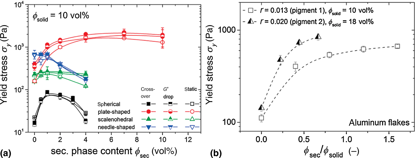
The influence of the particle size on the yield stress was investigated by Koos et al. for spherical, glass particles, where the dependence on the reciprocal radius was reproduced.[Reference Koos, Johannsmeier, Schwebler and Willenbacher36] The influence of the shape on the rheology was investigated by Maurath et al. using application-oriented particles.[Reference Maurath, Bitsch, Schwegler and Willenbacher30] They used spherical-, scalenohedral-, plate-, and needle-shaped particles made from precipitated calcium carbonate and aluminum flakes. All suspensions were prepared in the pendular state with a particle fraction of ϕ = 7 and 10 vol%. The impact of particle shape on the yield stress is shown in Fig. 5(a). The yield stress strongly increases with increasing amount of secondary phase for each of the shapes tested, with a maximum between ϕ sec/ϕ solid ≈ 0.1 and 0.2. The yield stress for spherical particles is almost one decade lower than the other particle shapes at the 1 vol% secondary phase peak. The differences in this rheological behavior for these differently shaped particles are assumed to be related to the shape of the capillary bridges formed in the suspensions.[Reference Maurath, Bitsch, Schwegler and Willenbacher30] For example, the contact area and corresponding capillary force are lower in spheres than for equally sized plates. This trend is clearly shown in Fig. 5(b), where data from two different aspect ratios as a function of ϕ sec/ϕ solid are shown. The capillary suspensions with flakes with the larger flat area result in higher yield stress values for the same ratio of secondary phase amount to a solid fraction. The particle shape also influences the aggregation of particles caused by oversaturated bridges.
(a) Yield stress σ y versus secondary phase content ϕ sec for capillary suspensions made of calcium carbonate particles with varying particle shapes. Yield stress was determined by oscillatory shear experiments (crossover of G′ and G″ in amplitude sweep; drop of G′) and with steady shear experiments (vane geometry). (b) Yield stress σ y versus  $\phi _{\sec} /\phi _{{\rm solid}} $ for suspensions made of aluminum flakes with varying aspect ratio (R) in a mixture of paraffin oil and mineral spirit and pure water as the secondary fluid. Figure from Maurath et al.,[Reference Maurath, Bitsch, Schwegler and Willenbacher30] reprinted with permission. Copyright 2016 Elsevier.

The saturation of the bridges and the aggregation of particles is shown in the location of the yield stress peak. This transition is integrated into the function g(V bridge/R 3) in Eq. (2). This transition from a pendular to funicular state was examined in the rheological measurements of Heidlebaugh et al. and Domenech and Velankar and confocal measurements of Bossler and Koos.[Reference Bossler and Koos19, Reference Domenech and Velankar21, Reference Heidlebaugh, Domenech, Iasella and Velankar22] By considering the volume needed for a third particle to impinge on a capillary bridge joining two spherical particles, Heidlebaugh et al. calculated a transition at ϕ sec/ϕ solid = 0.22, assuming four contacts per particle. Despite the arbitrary value for the coordination number, this transition points matches quite well with observed yield stress peak in their data.[Reference Domenech and Velankar21] Bossler and Koos directly measured the average bridge size for pendular state samples at 40° and 61°.[Reference Bossler and Koos19] At the same amount of added secondary fluid, the 61° sample has more binary bridging (pendular state) than the funicular 40° sample. This transition is consistent with the required bridge sizes calculated using the Flemmer criteria.[Reference Flemmer37]
The influence of the secondary and solid volume fractions was investigated by Bossler et al. under the assumption that the yield stress (or other macroscopic property) is power-law function of the solid volume fraction,
 $$X\left( {\phi _{{\rm solid}}} \right) \propto \phi _{{\rm solid}} ^{\,f\,(D)}, $$
where the constant X is a placeholder for a rheological property, such as the yield stress.[Reference Bossler, Maurath, Dyhr, Willenbacher and Koos38] In Eq. (3), the power exponent is assumed to be a function of the fractal dimension D, which can be calculated from the slope from the solid volume fraction against the yield stress, after Piau et al.,[Reference Piau, Dorget, Palierne and Pouchelon39] as
 $$f\,(D) \equiv m = \displaystyle{4 \over {3 - D}}.$$
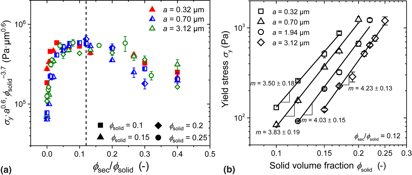
The data for measurements on Al2O3 suspensions for ceramics are shown in Fig. 6. A master curve is shown in Fig. 6(a), and the yield stress values at the peak secondary fluid ratio of ϕ sec/ϕ solid = 0.12 are shown in Fig. 6(b) as a function of the solid volume fraction. The calculated exponents D indicate an increase in the fractal dimension for the alumina-based capillary suspensions with increasing particle size from D = 1.86 to 2.05. The reason for this change in the dimensionality toward the value of an unstructured value of 3 with increasing particle size is hypothesized to be caused by the relative reduction of capillary force to gravity.[Reference Bossler, Maurath, Dyhr, Willenbacher and Koos38] The dimensionality was also calculated by Domenech and Velankar for their glass–polymer system as between 1.79 and 1.98 depending on the method used.[Reference Domenech and Velankar21]
(a) Yield stress master curve for Al2O3-based capillary suspensions. Different symbols represent varying solid volume fractions and symbol fillings and color signify different particle sizes. The dashed line defines the position of the yield stress maximum at  $\phi _{\sec} /\phi _{{\rm solid}} = 0.12$. (b) Yield stress σ y of Al2O3-based capillary suspensions as a function of the solid volume fraction ϕ solid at a fixed ratio of
 $\phi _{\sec} /\phi _{{\rm solid}} = 0.12$ for the four different mean particle radii. Reprinted with permission from Bossler et al.[Reference Bossler, Maurath, Dyhr, Willenbacher and Koos38] Copyright 2018 AIP Publishing.

This concept of two different dimensions was expanded by Bossler et al., where two different fractal dimensionalities were measured from either yield stress or oscillatory shear data. The network backbone dimensionality of D = 1.86 − 2.05 was calculated from the yield stress (as shown above) using the scaling model from Piau et al.[Reference Piau, Dorget, Palierne and Pouchelon39] An intrafloc dimension with D = 2.57 − 2.74 was calculated from the oscillatory data using the scaling model of Wu and Morbidelli.[Reference Wu and Morbidelli40] This discrepancy was explained by the inhomogeneity of the microstructure of the capillary suspensions as shown in Fig. 7.[Reference Bossler, Maurath, Dyhr, Willenbacher and Koos38] The fractal dimension calculated with the Piau et al. model is expected to represent the structure of the network backbone, whereas the model from Wu and Morbidelli describes the fractal dimension inside the aggregates. Due to the locally higher particle volume fraction and more compact structure, the floc dimension is much higher than the backbone dimension.[Reference Bossler, Maurath, Dyhr, Willenbacher and Koos38] This inhomogeneous structure was confirmed with confocal images of the network and flocs.[Reference Bossler, Maurath, Dyhr, Willenbacher and Koos38]
Schematic drawing of capillary suspension networks showing the percolation of individual flocs, each with a radius a. The yield stress measurements are dominated by the weak interfloc connecting regions (network backbone), and the shear modulus is dominated by the structure of the flocs themselves. Reprinted with permission from Bossler et al.[Reference Bossler, Maurath, Dyhr, Willenbacher and Koos38] Copyright 2018 AIP Publishing.

In addition to the parameters described above, which gives us several methods to tune and to control capillary suspensions, we must also consider the preparing and mixing conditions and their influence on the rheological properties of the pastes. Bossler et al. showed that the yield stress and shear moduli depend on the size and distribution of secondary phase droplets created during sample preparation.[Reference Bossler, Weyrauch, Schmidt and Koos31] In this paper, they used different preparation conditions for several different pendular state model systems. Using the dissolver stirrer to turbulently mix the capillary suspensions, the stirring speed and stirring time were varied. For the network in the pendular state, increasing mixing speeds lead to better droplet breakup, but spherical agglomeration was favored at longer times. These changes were monitored by changes in the yield stress with confirmation from microscope images. These suspensions were subsequently mixed with a ball mill where the mixing time was varied. This additional mixing was observed to be beneficial for the resulting sample strength with a plateau in the strength reached after 9.5 h.[Reference Bossler, Weyrauch, Schmidt and Koos31] Pre-emulsification of the secondary fluid in the bulk fluid, before addition of the particles, was also tested. Here, the conditions during emulsification controlled the properties of the final suspensions. This method has also been used by Domenech and Velankar as a way to mix and homogenize their samples.[Reference Domenech and Velankar2] Indeed, both Bossler et al. and Domenech and Velankar show that enhanced droplet breakup of the secondary fluid leads to stronger particle networks with more homogeneous network structures.[Reference Domenech and Velankar2, Reference Bossler, Weyrauch, Schmidt and Koos31] The structure and strength of the created suspension systems depend strongly on the sample preparation method and the energy input during mixing of the sample.[Reference Bossler, Weyrauch, Schmidt and Koos31]
Koos and Willenbacher carried out studies to investigate the configuration of the particulate network and its influence on the rheology of the capillary state suspensions.[Reference Koos and Willenbacher18] They determined that the pastes in the capillary state had a sample-spanning network composed of clusters of particles surrounding secondary fluid droplets. The simulation, which varied the three-phase contact angle and assumed spherical particles as well as a monomodal particle size distribution, predicted changes to the yield stress with added secondary fluid. These networks should have a lower yield stress compared with the pendular state because of the decreasing energy of these clusters with increasing contact angle. These clusters form when multiple particles come into contact with a drop and can only relax into the lowest energetically favored state when the drop is completely surrounded by particles.
Creating these clusters occurs with increasing energy input during mixing. A strong increase in yield stress was measured with increasing stirring speeds at a single stirring time and at longer times for a single speed using a turbulent dissolver stirrer.[Reference Bossler, Weyrauch, Schmidt and Koos31] The corresponding standard deviation between measurements decreases, indicating a more homogeneous structure, particularly when faster stirring speeds are used. This influence of the stirring speed is stronger for the capillary state than for the pendular suspensions.[Reference Bossler, Weyrauch, Schmidt and Koos31] During mixing, however, existing clusters break leaving drops sitting on the particle surface. These drops, shown in the right-hand image in Fig. 1, do not move around the droplet and combine with their neighbors due to the wetting angle >90°.[Reference Koos and Willenbacher18, Reference Bossler and Koos19] They do not take part in the structure formation or contribute to the yield stress. They may, however, cause the aging in capillary state suspensions. This aging was detailed in the work of Koos et al. where a change in the rheological behavior was observed for long time intervals.[Reference Koos, Kannowade and Willenbacher41] The droplets may move and cause rearranging of the clusters under oscillatory shear, giving rise to the assisted aging in these capillary suspensions systems.[Reference Bossler and Koos19]
In this review and in the experimental paper with Yang et al., Velankar looked at the various microstructures that could be created with different fractions for particles and liquids.[Reference Yang, Roell, Echavarria and Velankar24, Reference Velankar42] They demonstrated that it is possible to produce porous polymer blends with different morphologic structures. These structures ranged from the pendular state suspensions outlined earlier as well as large, interfacially jammed bicontinuous structures. These structures form when the particle loading is above 20% and the contact angle is close to 90°. The amount of wetting fluid should be slightly less than the non-preferentially wetting fluid.
Perspectives and conclusion
Capillary suspensions have been demonstrated to be beneficial for the creation of smart materials. It is possible to create a porous material with either polymeric or sintered bridges where the desired properties, such as porosity and pore sizes, can be adapted for specific applications. The incorporation of a hydrogel can even be used to tune these properties with temperature.
Capillary suspension pastes can be used as precursors in capillary foams,[Reference Zhang, Allen, Zhao, Deheyn, Behrens and Meredith43] glass filters,[Reference Maurath, Dittmann, Schultz and Willenbacher28] and sintered ceramics.[Reference Dittmann and Willenbacher16, Reference Dittmann, Maurath, Bitsch and Willenbacher17, Reference Dittmann, Koos and Willenbacher27] These porous materials are produced by using a binding secondary fluid, like PEO or a sucrose solution. The secondary fluid crystallizes during the subsequent debinding process and serves as a local sintering assistant. It keeps the particles close to each other and provides and improves the sintering between the particles. The final material properties of the porous bodies can be controlled very easily by varying the amount of the secondary fluid. With increasing amounts of the secondary phase in the region ϕ sec = 0–2.5 vol%, the porosity can be increased from 43% to 55%. Meanwhile, the pore size distribution in this region becomes broader from the monomodal distribution at small pores around 10 µm to a broad size distribution larger pores up to 40 µm. This implies that using capillary suspensions, the structure of ceramic materials can be tuned and adapted for desired application only by variation of the amount of secondary fluid. It should be possible to further tune the structure of these porous bodies, decoupling the pore size from the porosity, by adapting the mixing conditions, contact angles, and particle shapes.
While these properties are so far superior to the porous bodies created using monomers or polymeric solutions, the structure of the bridges and the resulting porous material can be preserved during the solidifying process in the polymeric route. Shrinkage during processing still causes problems for sintered materials. While the general wet network structure is preserved in these sintered bodies, the solid material shrinks during debinding and sintering.[Reference Maurath and Willenbacher29] This is a drawback, which needs more investigation at this moment.
A further push toward systems that can be tuned with external stimuli, such as the hydrogel bridging fluid of Das et al.,[Reference Das, Dunstan, Stoyanov, Starck and Paunov20] is expected in the future. A new way to create extraordinary properties was recently investigated by Bharti et al., where they used the capillary bridging between magnetic nanoparticles coated with a liquid lipid shell to create the assembly of ultraflexible microfilaments and network structures.[Reference Bharti, Fameau, Rubinstein and Velev44] The capillary and magnetic forces allowed these systems to be restructured after external stimuli, which could be perfectly applied in micromanipulators, microbots with ultrasoft joints, or even magnetically self-repairing gels.[Reference Bharti, Fameau, Rubinstein and Velev44]
This push toward the use of new materials must be combined with an increased flexibility in the choice of the bulk and bridging fluids. Dunstan et al.[Reference Dunstan, Das, Starck, Stoyanov and Paunov5] found a way to tune the wetting effects by mixing a hydrophobizing agent into the bridging fluid during the formation of capillary suspensions, as shown in Fig. 8.
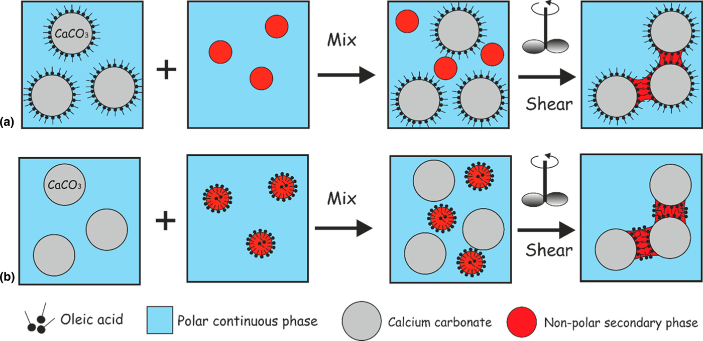
In situ hydrophobization of calcium carbonate particles in a capillary suspension. Processing route to create capillary suspensions using (a) pre-hydrophobized calcium carbonate with unmodified non-polar secondary phase and (b) in situ hydrophobization of calcium carbonate using modified non-polar secondary phase. Reprinted with permission from Dunstan et al.[Reference Dunstan, Das, Starck, Stoyanov and Paunov5] Copyright 2018 American Chemical Society.
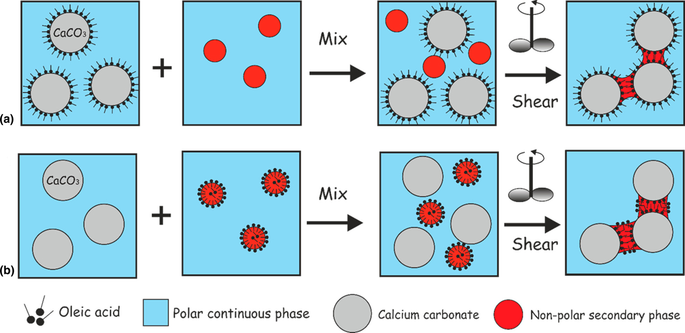
Dunstan et al. demonstrated two processes to form capillary suspensions from calcium carbonate particles dispersed in a polar liquid phase (e.g., glycerol or water). In the more traditional method, the non-polar secondary fluid is to add to the calcium carbonate, which was pre-hydrophobized by oleic acid, suspended in a polar continuous phase [Fig. 8(a)]. As shown in Fig. 8(b), the oleic acid can be mixed into the non-polar secondary phase, which is then added to the suspension of untreated particles in the polar solvent. In both cases, the oleic acid transforms changes in the contact angle and wetting properties.[Reference Dunstan, Das, Starck, Stoyanov and Paunov5] This method opens up possibilities for increasing the number of particle–fluid combinations, particularly to create capillary suspensions where water is used as the bulk fluid, opening up new possibilities for environmentally friendly materials.
This in situ hydrophobization can also be used to create more capillary state suspensions. Up until now, suspensions, where the secondary fluid does not preferentially wet the particles, have not been used in the material design. The unique structure of these capillary state particle networks and the drops on the surface, which give rise to the observed aging behavior, may open up new areas and these structures should be incorporated into future designs of smart materials.
Acknowledgments
The authors would like to acknowledge the financial support from the European Research Council under the European Union's Seventh Framework Program (FP/2007–2013)/ERC Grant Agreement no. 335380.