





1. Introduction
Anterior cruciate ligament (ACL) injuries are among the most frequent sports-related knee injuries, often resulting in significant knee instability due to poor intrinsic healing capacity caused by limited ligament vascularization and adverse intra-articular conditions. Consequently, ACL reconstruction (ACLR) using autografts (bone-patellar tendon-bone or hamstring tendons) or, less commonly, allografts has become standard practice to restore knee stability (Wu et al., Reference Wu, Kator, Zarro and Leong2022). Independent of surgical technique, early postoperative rehabilitation is crucial for regaining function, typically involving gradual knee mobilization within protective limits over several weeks (Cavanaugh and Powers, Reference Cavanaugh and Powers2017; Wu et al., Reference Wu, Kator, Zarro and Leong2022). Prolonged immobilization in rigid extension braces, although protective, is associated with rapid muscle atrophy, cartilage degeneration, reduced joint mobility, and increased fall risk (Veldhuizen et al., Reference Veldhuizen, Verstappen, Vroemen, Kuipers and Greep1993; Bączkowicz et al., Reference Bączkowicz, Skiba, Falkowski, Domaszewski and Selkow2020; Rüther et al., Reference Rüther, Boban, Paus, Loose, Willauschus, Bail and Millrose2022).
To mitigate these adverse effects, modern rehabilitation emphasizes controlled early knee movement using adjustable braces that progressively allow flexion, balancing graft protection against muscle and joint recovery (Wilk et al., Reference Wilk, Macrina, Cain, Dugas and Andrews2012). The commercial functional ACL braces are typically designed to mitigate injury-relevant mechanisms such as anterior tibial translation, valgus angulation, and hyperextension (Heyworth et al., Reference Heyworth, Berube, Gossman, Milewski and Bixby2025). Current braces predominantly use rigid mechanical stops to enforce range-of-motion (ROM) limits. Despite their widespread clinical use, there is little quantitative evidence that impacts against rigid flexion stops directly increase ACL-graft loading or revision risk after ACL reconstruction. Rigid end stops nevertheless create an abrupt orthosis-user interaction and may cause discomfort. The present study therefore evaluates whether the braking interaction can be distributed over a larger, but still limited angular interval. Passive soft-stop mechanisms, such as elastomer bumpers or viscous dampers (Kirchner et al., Reference Kirchner, Phillips and Bounardjian2005; DonJoy, 2025), can reduce impact severity but remain mechanically fixed, are hard to tune for individual patients and rehabilitation phases, and are prone to wear or failure under repeated high-load cycles (Greenfield et al., Reference Greenfield, Hwang, Davies and McDaid2017). In contrast, active orthoses and exoskeletons can implement software-defined, state-dependent virtual soft stops, smoothly decelerating joint motion as limits are approached algorithmically (Murray et al., Reference Murray, Ha and Goldfarb2014; Park et al., Reference Park, Akbas, Eckert-Erdheim, Sloot, Nuckols, Orzel, Schumm, Ellis, Awad and Walsh2020). Yet, software-defined flexion soft stops implemented via gain-scheduled proportional-derivative (PD) torque control have not been systematically evaluated in powered knee orthoses for configurable flexion restriction, nor compared head-to-head against conventional rigid stops using gait kinematics, muscle activity, and subjective user experience.
Many current brace concepts and commercial functional ACL braces primarily target injury-relevant mechanisms such as hyperextension, valgus loading, and anterior tibial translation. In contrast, early postoperative rehabilitation may also involve temporary, stage-specific restrictions of knee flexion during walking and exercise progression. The relevant design problem is therefore not chronic suppression of knee motion, but the implementation of a clinician-defined flexion bound that can be enforced smoothly and relaxed progressively as recovery advances. This motivates brace concepts that can provide adjustable flexion limiting without the abrupt end-stop interaction typical of rigid mechanical stops.
Passive compliant soft-stop concepts have also been explored. Greenfield et al. (Reference Greenfield, Hwang, Davies and McDaid2017) presented a soft-stop knee brace that used elastomer dampers around adjustable ROM pins to cushion end-range interaction in a single-subject pilot. This work is directly relevant because it shares the goal of reducing abrupt end-stop interaction, but the approach remained passive, non-phase-specific, and hardware-dependent. Importantly, the pilot also reported unexpected damper failure during gait and discussed cyclic and shear loading as probable contributors. ACL-reconstruction-related robotic and wearable rehabilitation systems have also begun to emerge, including wearable robot-assisted knee training after ACL reconstruction and gait-oriented resistance-based rehabilitation approaches (Johnson et al., Reference Johnson, Brown, Palmieri-Smith and Krishnan2022; Soma et al., Reference Soma, Mutsuzaki, Yoshioka, Kubota, Shimizu, Kanamori and Yamazaki2022). These systems highlight the potential of active, programmable rehabilitation devices in ACLR, but they mainly target exercise assistance, resistance training, or clinic-based neuromuscular rehabilitation rather than brace-like, gait-phase-specific ROM limiting during walking. Consequently, there remains a gap for powered knee orthoses that can implement adjustable flexion bounds as software-defined virtual soft stops while remaining transparent outside the protected phase.
Beyond early rehabilitation, functional bracing after ACL reconstruction remains prevalent, yet recent clinical reviews highlight limited and conflicting evidence regarding when bracing is beneficial and for whom (Heyworth et al., Reference Heyworth, Berube, Gossman, Milewski and Bixby2025). Open questions include the optimal brace concept, timing and duration of wear, and the role of patient-specific factors such as compliance, psychological confidence, and proprioceptive side effects (Heyworth et al., Reference Heyworth, Berube, Gossman, Milewski and Bixby2025). These uncertainties motivate brace concepts that are not only mechanically protective but also tunable and objectively evaluable with respect to kinematics, neuromuscular activity, and user perception. These considerations motivate the central question of this study: can a powered knee orthosis implement software-tunable, angle- and velocity-gated soft stops that limit swing-phase knee flexion while maintaining modest actuator demands and avoiding large compensatory kinematic changes during healthy gait?
To investigate this question, we introduce a gain-scheduled PD soft-stop controller integrated into a powered knee orthosis and evaluate it in a controlled treadmill experiment with healthy adults. Conceptually, the controller implements a state-dependent virtual wall that remains transparent during stance and early swing and engages when the knee approaches the prescribed flexion boundary while moving into flexion, with stiffness and damping increased in an angle- and velocity-gated manner. We frame this as a control-and-interaction problem under tight form-factor constraints: the orthosis should remain transparent throughout stance and most of swing, yet provide predictable, smooth deceleration only when approaching a clinically prescribed flexion boundary in late swing. We therefore designed the soft stop around four requirements: (i) angle- and motion-dependent engagement to avoid unintended resistance, (ii) smooth gain transitions with hysteresis to prevent chattering near the boundary, (iii) software-configurable braking strength through predefined presets, and (iv) layered safety through a virtual limit complemented by a passive mechanical stop.
We formulated three a priori hypotheses to structure the analysis:
-
• H1 (efficacy): the soft-stop controller caps terminal swing knee flexion angle and flexion velocity at prespecified flexion bounds compared to the motor-only (ortho plus) baseline.
-
• H2 (function): the controller preserves ankle push-off range of motion and limits compensatory changes in pelvic obliquity and trunk deviation compared to a rigid mechanical stop.
-
• H3 (muscle activity): the firm and mild soft-stop presets reduce mean standardized right-biceps-femoris average rectified value (ARV) during the swing interval relative to the rigid stop.
Our contribution is primarily integrative and comparative, building on established proportional-derivative torque control and variable-impedance concepts to (i) design a gated, angle- and velocity-dependent soft-stop profile for configurable knee-flexion limitation; (ii) integrate this controller into a modified commercial knee orthosis with a quasi-direct-drive actuator and dual-layer safety (virtual soft stop plus mechanical stop); and (iii) perform a counterbalanced crossover pilot study with
$ n=8 $
 healthy adults, directly comparing two impedance presets (firm, mild) against a rigid stop and orthosis-only and motor-only baselines using joint kinematics, surface electromyography (sEMG), and questionnaire-based user feedback.
The present study evaluates controller feasibility and human-orthosis interaction in healthy adults; it does not assess clinical efficacy, patient-specific safety after ACL reconstruction, or ACL/graft loading.
2. Methods
This section details the hardware used in the pilot study, the design of the soft-limit controller, the experimental protocol, data processing procedures, and the statistical analysis plan. The study protocol was approved by the Ethics Commission at the Faculty of Medicine at Friedrich-Alexander-Universität Erlangen-Nürnberg (approval no. 23-350-B). All participants provided written informed consent.
2.1. Hardware and sensors
2.1.1. Orthosis system
The knee orthosis is based on a commercially available brace (Genu CI Step Thru, Sporlastic, Nürtingen), modified with an active motor module (Sporlastic, 2023). An AK80-9 actuator (CubeMars, Nanchang) (CubeMars, 2023) and an MD80 motor controller (MAB Robotics, Poznań) (MABRobotics, 2025), providing a nominal torque of 9 N m (peak torque 22 N m), drive the polycentric knee joint. The polycentric design replicates the physiological shifting center of knee rotation, requiring an additional translational degree of freedom between the actuator and brace. This is achieved through our custom-designed, 3D-printed lateral bracket, publicly available in standard sizes (S, M, L) for both left and right braces (Scheidl et al., Reference Scheidl, Akarsu, Mehrkens, Schuh and Castellini2025). Interchangeable plastic inserts allow setting fixed limits to knee flexion and extension angles. The actuator’s high backdrivability (0.51 N m) ensures minimal resistance during passive joint motion, preserving natural gait characteristics (CubeMars, 2023). The entire active orthosis assembly weighs approximately 1.1 kg for size S (1.2 kg for size L); roughly 0.55 kg stem from the passive brace and 0.55 kg from the motor module. The motor housing and bracket have approximately the size of 40 cm
$ \times $
 15 cm
$ \times $
 13 cm. At the current prototype scale, orthosis hardware and electronics each cost on the order of 800 EUR.
2.1.2. Sensors and setup
Muscle activity was recorded using wireless Trigno Avanti sEMG sensors (Delsys Inc., Massachusetts), with eight channels placed bilaterally over the rectus femoris, biceps femoris, gastrocnemius medialis, and tibialis anterior (see Figures 1a and 1b). Because of the spatial constraints imposed by the orthosis shell, electrode positions deviated slightly from the SENIAM recommendations. They were positioned as close as practicable to the targeted muscle bellies while avoiding direct contact with the brace (Hermens et al., Reference Hermens, Freriks, Disselhorst-Klug and Rau2000).
Sensor placement and hardware overview: (a) Anterior view with the powered knee orthosis on the right leg and sEMG electrodes placed over rectus femoris and tibialis anterior. (b) Posterior view with the sEMG electrodes placed over biceps femoris and gastrocnemius medialis. (c) Participant walking at the DIERS 4D High Performance Lab with the active orthosis on the right leg. (d) Lateral close-up of the powered knee orthosis showing the actuator module and brace assembly (Scheidl et al., Reference Scheidl, Akarsu, Mehrkens, Schuh and Castellini2025). Panels (a) and (b) are adapted from (Z-Anatomy, 2025).

Figure 1. Long description
(a) Anterior illustration of both legs with the knee orthosis on the right leg; numbered electrode sites 1 and 2 lie over rectus femoris on the thighs and 5 and 6 over tibialis anterior on the shins. (b) Posterior illustration with electrode sites 3 and 4 over biceps femoris on the back of the thighs and 7 and 8 over gastrocnemius medialis on the calves. (c) Photograph from behind of a participant walking on an instrumented treadmill in a motion laboratory, wearing the black powered knee orthosis on the right leg. (d) Lateral close-up photograph of the powered knee orthosis on a leg, showing the round actuator module at the knee joint mounted on the brace frame with straps.
2.2. Soft-limit torque controller with angle- and velocity-gated gain-scheduling
Conceptually, the controller shapes the apparent knee joint behavior by adding an angle-dependent virtual spring-damper near a prescribed flexion boundary, so that the joint progressively feels stiffer and more damped rather than hitting a rigid stop. Technically, we realize this behavior using a proportional-derivative (PD) torque controller whose gains are scheduled as a function of proximity to the boundary and joint velocity, and are activated only when the knee is moving into flexion. We therefore refer to the method as an impedance shaping angle- and velocity-gated gain-scheduled PD soft stop.
2.2.1. Controller structure
The controller defines a normalized ramp region that begins at
$ {\theta}_{\mathrm{ramp}} $
 and ends at the passive mechanical safety boundary
$ {\theta}_{\mathrm{lim}} $
 . Within this region, the normalized proximity
$ \rho $
 to the safety boundary is computed:

Here,
$ {\theta}_{\mathrm{ramp}} $
 marks the beginning of the normalized ramp region and
$ {\theta}_{\mathrm{lim}} $
 the passive mechanical safety boundary. The operator

saturates the normalized proximity variable to the interval
$ \left[0,1\right] $
 . Importantly,
$ {\theta}_{\mathrm{ramp}} $
 does not mark the hard onset of perceptible braking, because actual controller engagement additionally depends on the gate thresholds
$ {\rho}_{\mathrm{on}} $
 and
$ {v}_{\mathrm{on}} $
 . A binary gating mechanism
$ G $
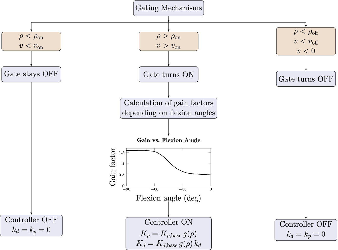
 (Figure 2) ensures the impedance only engages during meaningful movement toward the limit:

Thresholds
$ {\rho}_{\mathrm{on}}>{\rho}_{\mathrm{off}} $
 and
$ {v}_{\mathrm{on}}>{v}_{\mathrm{off}} $
 create hysteresis to prevent unwanted activation, ensuring smooth transitions without jitter. Intuitively, the gate turns on only when the knee is close enough to the flexion limit (
$ \rho \ge {\rho}_{\mathrm{on}} $
 ) and still moving into flexion above a small velocity threshold (
$ {v}_{\mathrm{on}} $
 ). It turns off when the knee moves away from the limit (
$ \rho \le {\rho}_{\mathrm{off}} $
 ) or slows down below
$ {v}_{\mathrm{off}} $
 , and retains its previous state between the separate on- and off-thresholds. The two threshold pairs (
$ {\rho}_{\mathrm{on}},{\rho}_{\mathrm{off}} $
 ) and (
$ {v}_{\mathrm{on}},{v}_{\mathrm{off}} $
 ) provide hysteresis and prevent chattering when the motion oscillates around the switching point.
Sequence-of-operation diagram for the soft-stop controller. The outer panels schematically summarize the gating logic based on proximity and angular velocity. The middle panel shows the resulting gain factor
$ g\left(\rho \right) $
 as a function of knee flexion angle, multiplying the base proportional and derivative gains.

Figure 2. Long description
A box labelled Gating Mechanisms splits into three branches. Left branch: conditions rho < rho_on and v < v_on lead to “Gate stays OFF” and “Controller OFF” with k_d = k_p = 0. Middle branch: conditions rho > rho_on and v > v_on lead to “Gate turns ON,” then to “Calculation of gain factors depending on flexion angles,” illustrated by a small inset plot of gain factor versus flexion angle in degrees, and finally to “Controller ON” with K_p = K_p,base times g(rho) and K_d = K_d,base times g(rho) times k_d. Right branch: conditions rho < rho_off, v < v_off and v < 0 lead to “Gate turns OFF” and “Controller OFF” with k_d = k_p = 0.
2.2.2. Gain scheduling
The impedance envelope
$ g\left(\rho \right) $
 smoothly increases stiffness and damping as the knee approaches the flexion limit, shaped by a polynomial ramp:

Here,
$ k>0 $
 is a dimensionless shape exponent controlling how strongly the gain increase is concentrated near the flexion boundary. For
$ k=1 $
 , the uncapped envelope increases linearly, whereas
$ k>1 $
 shifts more of the gain increase toward the boundary. The value used in this study was
$ k=4 $
 (Table 1). This envelope is exponentially smoothed to mitigate sensing noise and abrupt changes:

with a soft-start mechanism after gate activation. Gains are finally scaled using the smoothed envelope, ensuring higher damping at higher velocities and minimal resistance at lower speeds:


Figure 3 illustrates the controller operation and the reference thresholds over a representative mean gait cycle. The left panel shows the knee angle together with the normalized gain envelope, whereas the right panel shows the corresponding scheduled controller targets. As knee flexion increases in late swing, the scheduled stiffness and damping rise and operate within the prescribed boundary before the knee reverses direction.
Controller operation during an averaged gait cycle (mild stop preset). Left: knee flexion angle (blue dashed) and normalized gain envelope
$ g\left(\rho \right) $
 (green). Reference thresholds
$ {\theta}_{\mathrm{ramp}} $
 ,
$ {\theta}_{\mathrm{on}} $
 ,
$ {\theta}_{\mathrm{lim}} $
 , and the virtual target (
$ {45}^{\circ } $
 ) are shown as horizontal lines. Right: scheduled stiffness
$ {K}_p\;\left(\mathrm{N}\;\mathrm{m}\;\mathrm{ra}{\mathrm{d}}^{-1}\right) $
 (grey) and damping
$ {K}_d\;\left(\mathrm{N}\;\mathrm{m}\;\mathrm{s}\;\mathrm{ra}{\mathrm{d}}^{-1}\right) $
 (black) over the same gait cycle. Background shading denotes gait phases (LR, MS, PS, TS).

Figure 3. Long description
Both panels plot knee angle (blue dashed line, 0 to 65 degrees) against gait cycle (0 to 100 percent), with background bands for loading response, mid stance, pre swing and terminal swing. Horizontal lines mark theta_ramp (15 degrees), theta_on (about 28.5 degrees), the virtual target (45 degrees) and theta_lim (60 degrees). The knee angle has a small peak of about 21 degrees in early stance and a main peak of about 62 degrees at roughly 75 percent of the cycle. Left: the normalized gain envelope g(rho) (green, right axis 0.30 to 0.70) starts at about 57 percent of the cycle, rises steeply in pre swing and levels off near 0.61 in terminal swing. Right: scheduled stiffness K_p (grey) and damping K_d (black) rise between about 62 and 72 percent of the cycle, with K_d peaking just before the knee angle maximum.
Summary of gain presets and shared controller parameters

Table 1. Long description
Rows: mild stop and firm stop. Base proportional and derivative gains are 10 and 20 for the mild stop and 50 and 70 for the firm stop; maximal scheduled gains K_p max and K_d max are 7 and 14 (mild) and 35 and 49 (firm). Shared by both presets: theta_on 28.5 degrees, theta_off 21.8 degrees, v_damp 0.60 rad/s, shape exponent k 4.00, f_max 0.70, smoothing factor alpha 0.25, theta_ramp 15 degrees, theta_lim 60 degrees, v_on 0.25 rad/s and v_off 0.07 rad/s. Proportional gains in Nm/rad, derivative gains in Nm s/rad.
Note: The proportional and derivative gains are given in
$ \mathrm{N}\;\mathrm{m}\;\mathrm{ra}{\mathrm{d}}^{-1} $
 and
$ \mathrm{N}\;\mathrm{m}\;\mathrm{s}\;\mathrm{ra}{\mathrm{d}}^{-1} $
 respectively,
$ \theta $
 in degree and velocities in
$ \mathrm{rad}/\mathrm{s} $
 .
The gain-scheduled soft-stop controller generated torque
$ {\tau}_{\mathrm{ss}} $
 is defined as:

Here, knee flexion and flexion velocity are defined as positive, and the reference velocity was set to
$ {\dot{\theta}}_{\mathrm{ref}}(t)=0 $
 . When the knee continues to move into flexion relative to the active reference, the resulting soft-stop torque is extension-directed and opposes further flexion. Independent of the gain-scheduled soft-stop law, the actuator used an internal transparency controller to reduce reflected friction from the motor and gearbox. This internal friction compensation was not a separately tuned term of the soft-stop controller. In the ortho plus condition, the soft-stop contribution was disabled, and only the internal transparency compensation remained active. In the firm and mild soft-stop conditions, the scheduled impedance gains were activated relative to this transparent actuator baseline.
2.3. General controller tuning
2.3.1. Biomechanical rationale
Human knee mechanics vary substantially across gait phases. Perturbation-based identification during walking reported swing-phase knee stiffness of
$ 0 $
 –
$ \approx 3.5\;\mathrm{N}\;\mathrm{m}\;\mathrm{ra}{\mathrm{d}}^{-1} $
 and damping of
$ \approx 0.02 $
 –
$ 0.14\;\mathrm{N}\;\mathrm{m}\;\mathrm{s}\;\mathrm{ra}{\mathrm{d}}^{-1} $
 (van der Kooij et al., Reference van der Kooij, Fricke, van’t Veld, Vallinas Prieto, Keemink, Schouten and van Asseldonk2022). Separate gait analyses reported phase-dependent knee quasi-stiffness values up to
$ \approx 176\;\mathrm{N}\;\mathrm{m}\;\mathrm{ra}{\mathrm{d}}^{-1} $
 and an average peak knee moment of
$ \approx 0.46\;\mathrm{N}\;\mathrm{m}\;\mathrm{k}{\mathrm{g}}^{-1} $
 (Huang et al., Reference Huang, Zhang, Yu, MacLean, Zhu, Di Lallo, Jiao, Bulea, Zheng and Su2022). Published knee-moment data provide an additional order-of-magnitude reference (Zhang et al., Reference Zhang, Liu, Han, Wang, Yan, Ma and Wei2020). These values informed the initial controller scale, whereas the final gains were tuned empirically on the device. The mechanical rationale concerns the external brace-limb interaction rather than direct ACL or graft loading. Decelerating knee flexion requires negative mechanical work. For a comparable reduction in rotational kinetic energy, distributing this work over a larger angular excursion lowers the mean resisting torque and avoids concentrating deceleration at a single rigid end-stop event. The soft-limit controller therefore targets low impedance through most of the gait cycle and increases stiffness and damping only as the configured flexion region is entered, before contact with the passive
$ {60}^{\circ } $
 safety stop. ACL force depends on the combined tibiofemoral loading state, muscle forces, and joint kinematics (Markolf et al., Reference Markolf, Burchfield, Shapiro, Shepard, Finerman and Slauterbeck1995). These internal tissue loads were not estimated in this study. The present analysis therefore addresses flexion-limiting performance and external user interaction, not tissue-protection efficacy.
2.3.2. Implemented parameters and presets
The controller parameters were chosen by combining literature-derived order-of-magnitude estimates for swing-phase knee impedance and physiological knee moments (Zhang et al., Reference Zhang, Liu, Han, Wang, Yan, Ma and Wei2020; Huang et al., Reference Huang, Zhang, Yu, MacLean, Zhu, Di Lallo, Jiao, Bulea, Zheng and Su2022; van der Kooij et al., Reference van der Kooij, Fricke, van’t Veld, Vallinas Prieto, Keemink, Schouten and van Asseldonk2022), as well as hardware constraints, and pilot tuning on the actual device. The passive boundary
$ {\theta}_{\mathrm{lim}}={60}^{\circ } $
 was retained as a hardware fail-safe and aligned with the clinical partner’s early-phase practice, whereas the intended virtual flexion bound was approximately
$ {45}^{\circ } $
 . The rigid-stop comparator was therefore set to
$ {45}^{\circ } $
 to ensure measurable engagement during healthy treadmill walking, while the soft-stop conditions retained the
$ {60}^{\circ } $
 passive stop as a safety layer. The ramp onset
$ {\theta}_{\mathrm{ramp}}={15}^{\circ } $
 was chosen to allow gain buildup over late swing rather than a late abrupt rise. The hysteresis thresholds
$ \left({\rho}_{\mathrm{on}},{\rho}_{\mathrm{off}}\right) $
 and
$ \left({v}_{\mathrm{on}},{v}_{\mathrm{off}}\right) $
 were selected to prevent chatter around onset and release. The polynomial exponent
$ k=4 $
 keeps the gain envelope low over most of the ramp and increases resistance primarily near the boundary. The cap
$ {f}_{\mathrm{max}}=0.70 $
 was selected empirically as an independent, quick-to-scale parameter that limits end-range interaction intensity without changing the ramp geometry or gating logic. The smoothing factor
$ \alpha =0.25 $
 reduced jitter without introducing excessive delay. The damping scale
$ {v}_{\mathrm{damp}}=0.60\;\mathrm{rad}/\mathrm{s} $
 preserved natural interaction at low velocities while allowing stronger damping during faster flexion. The base gains
$ {K}_{p,\mathrm{base}} $
 and
$ {K}_{d,\mathrm{base}} $
 were chosen such that the mild preset prioritized low interference and the firm preset prioritized stricter braking. Literature on physiological swing-phase knee impedance and knee flexion moments provided the target order of magnitude, but the final values were tuned empirically on the present orthosis to achieve stable, smooth interaction without an overly abrupt hard-wall sensation. We evaluated two distinct impedance presets (see Table 1): Mild stop (
$ {K}_{p,\mathrm{base}}=10 $
 ,
$ {K}_{d,\mathrm{base}}=20 $
 ) yields maximal scheduled gains
$ {K}_p^{\mathrm{max}}=7\;\mathrm{N}\;\mathrm{m}\;\mathrm{ra}{\mathrm{d}}^{-1} $
 and
$ {K}_d^{\mathrm{max}}=14\;\mathrm{N}\;\mathrm{m}\;\mathrm{s}\;\mathrm{ra}{\mathrm{d}}^{-1} $
 . Firm stop (
$ {K}_{p,\mathrm{base}}=50 $
 ,
$ {K}_{d,\mathrm{base}}=70 $
 ) results in maximal gains
$ {K}_p^{\mathrm{max}}=35\;\mathrm{N}\;\mathrm{m}\;\mathrm{ra}{\mathrm{d}}^{-1} $
 and
$ {K}_d^{\mathrm{max}}=49\;\mathrm{N}\;\mathrm{m}\;\mathrm{s}\;\mathrm{ra}{\mathrm{d}}^{-1} $
 . These presets differ primarily in late-swing braking strength; mild prioritizes minimal interference while adhering to the lower boundaries of physiological flexion demands, whereas firm emphasizes stricter flexion capping and explores upper-boundary impedance gains. For the soft-stop conditions, we did not add a second mechanical stop at
$ {45}^{\circ } $
 . Instead, the impedance profile was tuned so that the knee was typically decelerated toward an effective virtual bound near
$ {45}^{\circ } $
 , while the passive
$ {60}^{\circ } $
 stop remained as a fail-safe. This leaves approximately
$ {15}^{\circ } $
 of headroom between the intended virtual bound and the passive safety stop, accommodating inter-subject variability and helping avoid mechanical impacts. Table 1 summarizes these parameters. Controller commissioning was performed once at device level before participant testing. Both presets shared the same ramp geometry, gate thresholds, hysteresis, smoothing, and velocity scaling, which remained fixed for all participants. The mild and firm presets differed only in their base proportional and derivative gains. No participant-specific gain optimization was performed during the experiment. Compared with a passive compliant stop, this approach requires more parameters during initial setup. However, the restriction level can be adjusted dynamically in software without replacing a spring, bumper, damper, or stop insert. Because this research is at the prototype stage and exploratory, tuning time and operator workload were not formally compared between the two approaches.
2.4. Experimental protocol and data processing
Eight healthy young adults (mean age
$ 26.9\pm 7.3 $
 years, four male/four female, average weight =
$ 72.91\pm 12.84 $
 kg) with no history of musculoskeletal or neurological disorders were recruited. All participants provided written informed consent before participation.
2.4.1. Design and conditions
A counterbalanced crossover design with six gait conditions was used (see Table 2):
-
• Physiological gait (physio): walking without the orthosis.
-
• Orthosis only (ortho only): the brace worn without the motor assembly, representing the passive effects of the shell and strapping.
-
• Orthosis plus motor (ortho plus): the brace worn with the motor active and the soft-stop controller disabled. The actuator’s internal transparency controller reduced reflected friction from the motor and transmission, minimizing resistance to voluntary knee motion.
-
• Rigid stop (rigid stop): the orthosis with the mechanical 45° flexion stop in place, without the motor assembly, representing the current rehabilitation standard.
-
• Firm soft stop (firm stop): the orthosis with both the mechanical 60° safety stop and the firm impedance gain preset active, targeting a strict virtual flexion limit around 45°.
-
• Mild soft stop (mild stop): targeting the same flexion limit as in the firm condition but with a milder impedance gain preset.
Each condition was recorded three times, with each trial lasting approximately 6 s (2–3 complete strides per leg). Condition order followed Williams-design sequences intended to balance order and first-order carryover. Participants 1–6 formed one complete six-sequence block, whereas participants 7–8 received two repeated sequences; the complete
$ n=8 $
 allocation was therefore counterbalanced but not perfectly balanced (Williams, Reference Williams1949). The complete condition presentation order is listed in the Supplementary Table 7. The rigid-stop comparator used a mechanical
$ {45}^{\circ } $
 flexion stop. In the soft-stop conditions, the intended virtual flexion bound was approximately
$ {45}^{\circ } $
 , while an additional passive mechanical stop at
$ {60}^{\circ } $
 was retained as a safety layer.
Condition overview

Table 2. Long description
Physiological gait: no orthosis, no motor, no stop. Orthosis only: orthosis without motor or stop. Orthosis plus: orthosis with motor, no stop. Rigid stop: orthosis without motor, with a rigid stop at 45 degrees. Firm stop and mild stop: orthosis with motor, a rigid safety stop at 60 degrees and a soft stop at 45 degrees.
2.4.2. Task
Participants walked on the instrumented treadmill at a constant speed of 3 km/h, slightly below the average preferred walking speed of healthy adults. This reduced speed was selected to simulate potential gait performance in individuals undergoing early rehabilitation. For each condition, three repetitions consisting of 2–3 complete strides were recorded per leg. Five-minute breaks between repetitions minimized fatigue. Afterward, a questionnaire was completed for subjective user feedback.
2.4.3. Synchronization, gait segmentation, sEMG preprocessing and feature extraction
All data streams (motor encoder, DIERS 4D High Performance Lab kinematics, treadmill force plates, and sEMG) were synchronized using UNIX timestamps. Gait events were identified bilaterally as initial-contact (IC) and toe-off (TO) events from the instrumented treadmill force plates and processed in the DIERS pedogait/DICAM export. Each right gait cycle extended from ipsilateral IC to the subsequent ipsilateral IC and was divided into four consecutive intervals: loading response (LR; ipsilateral IC to contralateral TO), mid stance (MS; contralateral TO to contralateral IC), pre swing (PS; contralateral IC to ipsilateral TO), and terminal swing (TS; ipsilateral TO to the subsequent ipsilateral IC) (Perry and Burnfield, Reference Perry and Burnfield2010). The DIERS export label terminal swing is retained here.
Surface EMG was processed at 3705 Hz. Signals were notch-filtered at 50 Hz, zero-phase band-pass filtered from 20 to 450 Hz using a fourth-order Butterworth filter, and full-wave rectified. Confirmed signal-quality exclusions were applied before participant-sensor standardization. For each participant and sensor, the mean and standard deviation of all retained gait-cycle samples were calculated, and the signal was normalized to reflect
$ \left|z\right| $
 .
Within each cycle and event-defined interval, values below
$ {Q}_1-1.5\times \mathrm{IQR} $
 or above
$ {Q}_3+1.5\times \mathrm{IQR} $
 were clipped to the corresponding fence (Tukey, Reference Tukey1977). Mean standardized ARV was defined as the arithmetic mean of the clipped
$ \left|z\right| $
 samples, and
$ {q}_{95} $
 as their 95th percentile.
For the exploratory peak-timing descriptor,
$ \left|z\right| $
 was additionally low-pass filtered at 6 Hz using a fourth-order zero-phase Butterworth filter. Peak timing was defined as the relative location of the within-interval maximum, expressed from 0% at interval onset to 100% at interval end.
2.4.4. Outcome variables and stride-level summaries
Primary knee kinematics were obtained from the actuator encoder. The knee-angle signal from the DIERS 4D High Performance Lab (DIERS International GmbH, 2025) was used only as a secondary optical plausibility comparison and did not enter the controller calculation. Figure 4 shows the optical trajectory for the unrestricted motorized (ortho plus) condition, because this condition served as the motorized reference and allowed the encoder trajectory to be compared with an optical measurement without an active flexion limit. DIERS-derived ankle, pelvic, and trunk kinematics were analyzed separately as secondary outcomes.
Knee joint angles during an averaged gait cycle under ortho plus, firm stop, and mild stop conditions. The solid blue trace shows the optical reference from the DIERS 4D High Performance Lab for ortho plus; dashed traces show motor-encoder measurements for ortho plus, firm stop, and mild stop. Shaded bands indicate group mean
$ \pm $
 1 SD. Background colors denote the gait phases.

Figure 4. Long description
Knee angle (5 to 65 degrees) versus gait cycle (0 to 100 percent), with background bands for the gait phases and shaded bands of plus/minus 1 SD. The solid blue line is the optical (DIERS) reference for ortho plus; dashed lines are motor-encoder measurements for ortho plus (blue), firm stop (orange) and mild stop (yellow). All curves are similar during stance, between about 10 and 20 degrees. In swing, ortho plus peaks at about 57 degrees (encoder) to 62 degrees (optical) at roughly 77 percent of the cycle, whereas the mild stop levels off at about 41 degrees and the firm stop at about 33 degrees. All curves return to about 10 degrees at the end of the cycle.
For gait-compensation analysis, we additionally used DIERS-derived ankle angle as a metric for ground clearance and push-off range of motion (Schulz, Reference Schulz2011; Bartlett et al., Reference Bartlett, Shepherd and Lawson2023), pelvic obliquity to observe hip-hike compensation (Akbas et al., Reference Akbas, Prajapati, Ziemnicki, Tamma, Gross and Sulzer2019), and sideways trunk deviation to monitor spinal compensation (Christensen et al., Reference Christensen, Quammen, Rigby, Christiansen and Stevens-Lapsley2021). To obtain robust subject-level summaries, we computed for each outcome and condition the 95th percentile (
$ {q}_{95} $
 ) or 5th percentile (
$ {q}_{05} $
 ) over all strides in the relevant phase (e.g.,
$ {q}_{95} $
 flexion angle in TS,
$ {q}_{05} $
 extension velocity in PS).
2.4.5. Primary endpoints and outcome families
To keep inference aligned with the hypothesis structure (H1–H3), we grouped outcomes into three primary endpoint sets: (H1, efficacy) terminal swing knee flexion limitation and braking dynamics:
$ {q}_{95} $
 knee flexion angle in TS,
$ {q}_{95} $
 flexion velocity in TS, and resistive torque in TS (with PS values reported as a check for unintended interference outside late swing): (H2, function) compensatory kinematics relevant to clearance and push-off: ankle metrics (e.g., TS plantarflexion and PS push-off ROM) and proximal compensations (pelvic obliquity and trunk deviation in TS); and (H3, muscle activity) phase-specific EMG demand proxies, with primary focus on biceps femoris activity in terminal swing (mean ARV and
$ {q}_{95} $
 ARV). The contrasts evaluated rigid stop versus soft stops. All 15 pairwise condition contrasts of this endpoint formed the H3 multiplicity family. The
$ {q}_{95} $
 and peak-timing descriptors were exploratory and were adjusted within their corresponding endpoint families.
For multiple-comparison control, we applied false discovery rate correction within outcome families. Kinematic families were defined as joint
$ \times $
 phase
$ \times $
 metric, and EMG families as muscle
$ \times $
 side
$ \times $
 phase
$ \times $
 metric.
2.4.6. Statistical analysis
For the kinematic and actuator-torque endpoints, we fitted linear mixed-effects models with condition as a fixed effect (treatment-coded, reference = physiological gait) and participant random intercepts (Bates et al., Reference Bates, Mächler, Bolker and Walker2015). Models were fitted using restricted maximum likelihood (REML) for parameter estimation, and for likelihood-ratio tests of overall condition effects, models were refitted using maximum likelihood (ML) while keeping the same random-effects structure. Pairwise contrasts between conditions were evaluated with Wald
$ z $
 -tests. To control for multiple comparisons,
$ p $
 -values were adjusted within each family using the Benjamini-Hochberg false discovery rate (FDR) procedure (Benjamini and Hochberg, Reference Benjamini and Hochberg1995). Results are reported as group means with 95% confidence intervals, Hedges’
$ g $
 , and FDR-adjusted
$ {p}_{\mathrm{adj}} $
 -values with: †
$ .05\le {p}_{\mathrm{adj}}<.10 $
 ; *
$ {p}_{\mathrm{adj}}<.05 $
 ; **
$ {p}_{\mathrm{adj}}<.01 $
 ; ***
$ {p}_{\mathrm{adj}}<.001 $
 . For H3, cycle-level endpoint values were first averaged within trial. The retained trial means were analyzed using a linear mixed-effects model with condition as a fixed effect and participant as a random intercept. All 15 two-sided Wald
$ z $
 contrasts were adjusted using the Benjamini-Hochberg procedure.
2.4.7. Quality control and exclusions
For analysis, minor adjustments were necessary due to sensor or marker dropouts. Due to sweating, sensor and marker adhesion were compromised in subject four. This led to the loss of markers and sensors, resulting in the exclusion of the ankle angle, the right leg gastrocnemius, and the left leg rectus femoris from analysis. Due to similar circumstances, subject two was excluded from the left leg tibialis anterior and right leg rectus femoris analysis. Additionally, marker occlusion resulted in one firm and two mild stop trials from subject five being excluded. One technically invalid subject eight right-biceps-femoris rigid-stop trial was excluded.
2.4.8. Questionnaire
After the experimental trial, participants completed a custom-designed questionnaire evaluating their comfort, perceived effort, and overall experience across the different test conditions. Clinical literature suggests that brace-related effects may extend beyond mechanics, including psychological confidence and potential proprioceptive trade-offs, which can ultimately influence acceptance and adherence (Heyworth et al., Reference Heyworth, Berube, Gossman, Milewski and Bixby2025). The questionnaire consisted of nine items, each rated for each condition. An additional free-text field allowed participants to provide open-ended feedback. Responses were recorded using scales ranging from
$ 0 $
 to
$ 10 $
 . Depending on the question, the scale direction varied: in some items,
$ 0 $
 indicated low agreement or minimal perception, whereas in others, it indicated strong agreement. The questionnaire was developed using validated instruments and established literature, incorporating elements from the Orthotics and Prosthetics User Survey (OPUS) (Heinemann et al., Reference Heinemann, Bode and O’Reilly2003), System Usability Scale (SUS) (Brooke, Reference Brooke, Jordan, Thomas, Weerdmeester and McClelland1995), and the Return to Sport after ACL Injury Scale (ACL-RSI) (Müller et al., Reference Müller, Schmidt, Krüger-Franke and Rosemeyer2014), among others. The complete questionnaire is provided in the Supplementary Figure 9.
3. Results
We summarize the results along the three hypotheses. For H1, both soft-stop presets substantially reduced terminal swing knee flexion and flexion velocity relative to the motor-only baseline, while requiring only modest resistive torques. For H2, compensatory kinematics at the ankle, pelvis, and trunk remained small overall. Importantly, ankle push-off range of motion was preserved under soft stops but reduced under the rigid stop. For H3, the trial-mean participant-random-intercept LMM identified higher swing-interval right biceps femoris ARV with the rigid stop than with both orthosis baselines and both soft-stop presets.
3.1. Knee flexion control with impedance soft stops
We assessed knee kinematics using motor encoder and compared the averaged trajectories with DIERS optical knee angles as an independent plausibility reference. The optical data was not used for controller operation and was occasionally affected by marker occlusion and interpolation. Where markers were unobstructed, the encoder and optical trajectories showed similar temporal patterns (Figure 4).
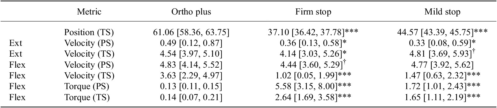
Encoder data revealed a clear restriction of terminal swing (TS) knee flexion under the impedance-based soft stops. Relative to ortho plus (
$ {q}_{95}={61.1}^{\circ } $
 , Table 3), the firm stop reduced TS flexion to
$ {37.1}^{\circ } $
 (
$ {p}_{\mathrm{adj}}<.001 $
 ,
$ \left|g\right|=2.26 $
 ) and the mild stop to
$ {44.6}^{\circ } $
 (
$ {p}_{\mathrm{adj}}<.001 $
 ,
$ \left|g\right|=1.36 $
 ), consistent with the intended virtual boundary near
$ {45}^{\circ } $
 . Similarly, peak flexion velocities during TS showed substantial reductions: the firm stop condition lowered peak velocity to
$ 1.02\;\mathrm{rad}/\mathrm{s},\left|g\right|=1.73 $
 compared to ortho plus (
$ 3.63\;\mathrm{rad}/\mathrm{s} $
 ), while the mild stop reduced it to
$ 1.47\;\mathrm{rad}/\mathrm{s},\left|g\right|=1.60 $
 (both
$ {p}_{\mathrm{adj}}<.001 $
 ). Notably, changes in PS flexion were minor and non-significant. Similarly, extension velocity during TS also showed little to no changes (see Table 3).
Knee kinematics and resistive torque in terminal swing (TS) and pre swing (PS)

Table 3. Long description
Values for ortho plus, firm stop and mild stop (95% confidence intervals are given in the table). Terminal-swing knee position: 61.06, 37.10*** and 44.57*** degrees. Extension velocity (rad/s) in pre swing: 0.49, 0.36* and 0.33*; in terminal swing: 4.54, 4.14* and 4.81 (dagger). Flexion velocity in pre swing: 4.83, 4.44 (dagger) and 4.77; in terminal swing: 3.63, 1.02*** and 1.47***. Resistive torque (N m) in pre swing: 0.13, 5.58*** and 1.72***; in terminal swing: 0.14, 2.64*** and 1.65***. Asterisks and dagger mark FDR-adjusted contrasts versus ortho plus.
Note: Entries are means [95% CI] of subject-level 95th percentiles. Position
$ {q}_{95} $
 in °; velocity
$ {q}_{05} $
 (extension) and
$ {q}_{95} $
 (flexion) in
$ \mathrm{rad}/\mathrm{s} $
 ; torque
$ \left|{q}_{05}\right| $
 in
$ \mathrm{N}\;\mathrm{m} $
 . Asterisks: FDR-adjusted contrasts versus ortho plus.
In the ortho plus condition, the gain-scheduled soft-stop contribution was disabled, and only the actuator-internal transparency compensation remained active. The recorded actuator-torque magnitude was approximately
$ 0.14\;\mathrm{N}\;\mathrm{m} $
 , consistent with low residual actuator interaction during unrestricted motorized walking. This compensation offsets internal actuator and transmission friction, resulting in residual friction below the motor’s backdrivability of
$ 0.51\;\mathrm{N}\;\mathrm{m} $
 (CubeMars, 2023). Mild stop peak resistance averaged around
$ 1.72\;\mathrm{N}\;\mathrm{m},\left|g\right|=0.89 $
 in PS and
$ 1.65\;\mathrm{N}\;\mathrm{m},\left|g\right|=1.81 $
 in TS, with peak PS values reaching
$ 3.69\;\mathrm{N}\;\mathrm{m} $
 . Firm stop peak resistance averaged around
$ 5.58\;\mathrm{N}\;\mathrm{m},\left|g\right|=2.02 $
 in PS and
$ 2.64\;\mathrm{N}\;\mathrm{m},\left|g\right|=3.03 $
 in TS, with peak PS values reaching
$ 14.55\;\mathrm{N}\;\mathrm{m} $
 . In summary, in this healthy cohort, the impedance-based soft stops reduced peak terminal swing knee flexion angles by approximately
$ 16\hskip-1pt \hbox{--} \hskip-1.5pt {24}^{\circ } $
 and flexion velocities by about
$ 2\hskip-1pt \hbox{--} \hskip-1.5pt 2.6\hskip2pt \mathrm{r}\mathrm{a}\mathrm{d}/\mathrm{s} $
 relative to the motor-only condition, while preserving pre swing flexion and extension velocities.
3.2. Impact of soft stops on ankle, pelvis, and trunk kinematics
We assessed the influence of soft limit controllers on gait kinematics by examining the movements of the ankle, pelvis, and trunk. Detailed numerical outcomes and statistical comparisons (FDR-corrected contrasts) are presented in Table 4.
Full-body kinematics by joint and phase

Table 4. Long description
Means for physio, ortho plus, firm stop, mild stop and rigid stop in degrees (95% confidence intervals are given in the table). Ankle ROM in pre swing: 14.06, 14.54, 14.54, 14.02, 10.08*. Ankle q05 in terminal swing: −21.64, −15.98***, −14.83***, −14.62***, −12.70***. Pelvic obliquity q95 in mid stance: 2.20, 2.31, 2.09, 1.84, 2.23; q05 in terminal swing: −2.12, −1.64*, −1.32***, −2.06, −1.09***; q95 in terminal swing: −0.41, 0.02, 0.18, −0.12, 0.84. Trunk deviation q95 in mid stance: 0.89, 0.72, 0.69, 0.63, 0.65; q05 in terminal swing: −1.40, −1.59, −1.62, −1.78*, −1.79*. Asterisks mark FDR-adjusted contrasts versus physio.
Note: Entries are the mean [95% CI] of the 95th percentiles. Asterisks indicate FDR-adjusted contrasts versus physiological gait (physio).
3.2.1. Ankle kinematics
The different conditions notably influenced the ankle plantar flexion during early terminal swing (see Figure 5). While soft limit conditions (firm and mild) closely matched the unrestricted motorized orthosis condition (ortho plus), the rigid stop condition significantly reduced plantar flexion (
$ -{12.70}^{\circ },{p}_{\mathrm{adj}}<.001,\left|g\right|=2.03 $
 ), compared to physiological gait (
$ -{21.64}^{\circ } $
 ). Any additional device attached produced a significant reduction in plantar flexion. Despite this, ankle ROM in push-off remained largely preserved across soft-limit conditions (Hedges’
$ \left|g\right|\approx 0.18 $
 ). Still, it was significantly compromised in the rigid stop condition (
$ {10.08}^{\circ } $
 vs.
$ {14.06}^{\circ } $
 in physiological gait,
$ {p}_{\mathrm{adj}}<.05,\left|g\right|=0.47 $
 ). An overlaid group-mean plot with standard deviations across all conditions is provided in the Supplementary Figure 10.
Condition-wise ankle joint angle over the averaged gait cycle. Each panel shows the group mean (solid line)
$ \pm 1 $
 SD (shaded band) for one condition. Panels are arranged as firm stop, mild stop, and rigid stop (top row), and physiological gait, ortho plus, and ortho only (bottom row). Background shading denotes gait phases (LR, MS, PS, TS).

Figure 5. Long description
Ankle angle (about −25 to +12 degrees) versus gait cycle (0 to 100 percent) for firm stop, mild stop and rigid stop (top row) and physiological gait, ortho plus and ortho only (bottom row), with plus/minus 1 SD bands and gait-phase shading. Each curve shows a small dip at loading response, a plateau in mid stance and a pronounced trough at about 68 to 70 percent of the cycle. The trough reaches about −23 degrees in physiological gait, about −17 to −19 degrees with ortho plus, ortho only, firm stop and mild stop, and about −14 degrees with the rigid stop. In mid stance, physiological gait stays near 0 to +2 degrees, while the orthosis conditions plateau at about +5 to +7 degrees.
3.2.2. Pelvic kinematics
Pelvic obliquity exhibited a clear condition-dependent pattern, as can be seen in Figure 6. In early terminal swing, all orthotic conditions showed a reduction in pelvic drop compared to physiological gait, with significant differences for ortho plus (
$ -{1.64}^{\circ },{p}_{\mathrm{adj}}<.05,\left|g\right|=0.18 $
 ), firm stop (
$ -{1.32}^{\circ },{p}_{\mathrm{adj}}<.001,\left|g\right|=0.10 $
 ), and rigid stop (
$ -{1.09}^{\circ },{p}_{\mathrm{adj}}<.001,\left|g\right|=0.28 $
 ), while the mild stop showed no significant drop (
$ -{2.06}^{\circ },\left|g\right|=0.28 $
 ). In contrast, mid stance pelvic kinematics showed minimal deviations and no significant differences between any conditions (Hedges’
$ \left|g\right|\approx 0.21 $
 ), indicating that the soft limit conditions, in particular, do not significantly disrupt pelvis orientation during weight acceptance. A corresponding overlaid plot is provided in the Supplementary Figure 11.
Condition-wise pelvic obliquity over the averaged gait cycle. Each panel shows the group mean (solid line)
$ \pm 1 $
 SD (shaded band). Panels are arranged as firm stop, mild stop, and rigid stop (top row), and physiological gait, ortho plus, and ortho only (bottom row). Positive values indicate contralateral pelvic hike.

Figure 6. Long description
Pelvic obliquity (−4 to +4 degrees) versus gait cycle (0 to 100 percent) for firm stop, mild stop and rigid stop (top row) and physiological gait, ortho plus and ortho only (bottom row), with plus/minus 1 SD bands and gait-phase shading. Positive values indicate contralateral pelvic hike. In all conditions the mean curve rises to a small positive peak during stance and falls to slightly negative values in terminal swing; the differences between conditions are small compared with the SD bands.
3.2.3. Trunk kinematics
Trunk imbalance was subtle, with overall deviations less than two degrees across all conditions (see Figure 7). Significant shifts toward increased trunk lean were only observed during terminal swing for the mild stop (
$ -{1.78}^{\circ },{p}_{\mathrm{adj}}<.05,\left|g\right|=0.35 $
 ) and rigid stop conditions (
$ -{1.79}^{\circ },{p}_{\mathrm{adj}}<.05,\left|g\right|=0.33 $
 ) compared to physiological gait (
$ -{1.40}^{\circ } $
 ). During mid stance, trunk kinematics remained consistent across conditions, demonstrating minimal and statistically non-significant differences of soft limits and orthotic conditions on trunk stability during stance (
$ \left|g\right|\approx 0.24 $
 ). A corresponding overlaid plot is provided in the Supplementary Figure 12.
Condition-wise trunk lateral deviation over the averaged gait cycle. Each panel shows the group mean (solid line)
$ \pm 1 $
 SD (shaded band). Panels are arranged as firm stop, mild stop, and rigid stop (top row), and physiological gait, ortho plus, and ortho only (bottom row). Positive values indicate deviation toward the braced (right) side.

Figure 7. Long description
Trunk lateral deviation (−3 to +2.5 degrees) versus gait cycle (0 to 100 percent) for firm stop, mild stop and rigid stop (top row) and physiological gait, ortho plus and ortho only (bottom row), with plus/minus 1 SD bands and gait-phase shading. Positive values indicate deviation toward the braced right side. In every condition the mean curve starts at about −1 to −1.5 degrees, rises to a peak of about +0.3 to +0.8 degrees at 40 to 45 percent of the cycle and declines to about −1.2 to −1.7 degrees in terminal swing.
3.3. Phase-specific muscle activation under soft stop control
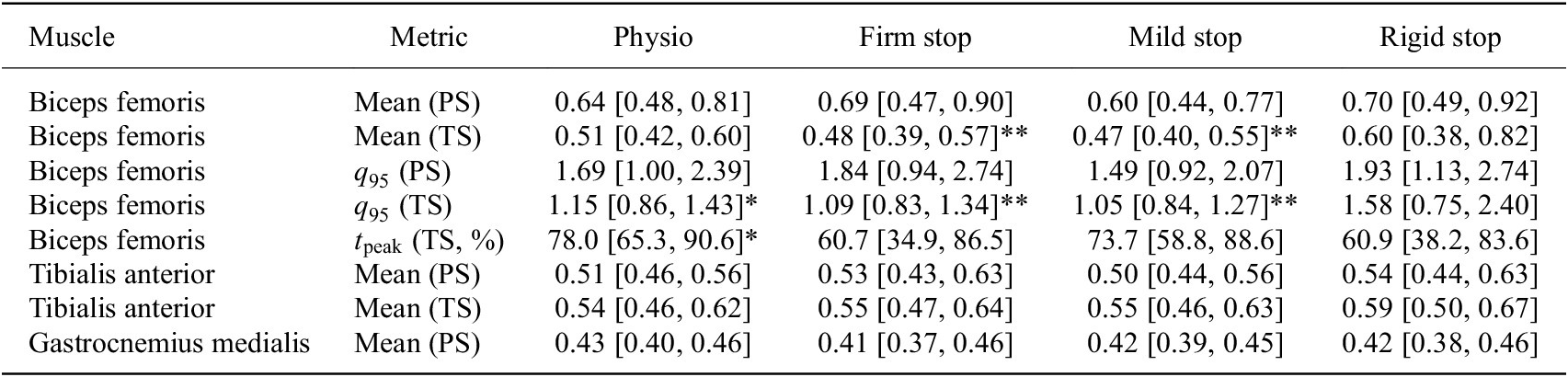
We evaluated right-biceps-femoris activity during the terminal swing interval. Participant-level descriptive summaries are reported in Table 5, and Figure 8 shows the corresponding distributions. Inferential contrasts were based on the trial-mean participant-random-intercept LMM. An important additional consideration was whether the orthosis on the right leg induced compensatory muscle activation in the contralateral (left) leg. However, our analysis revealed no systematic left-leg compensation pattern across the evaluated muscles (rectus femoris, biceps femoris, tibialis anterior, gastrocnemius) and gait phases (PS, TS). Changes were either right-dominant or bilateral reductions, with no consistent up-regulation observed in the contralateral side.
Right-leg EMG summary

Table 5. Long description
Participant-level means for physio, firm stop, mild stop and rigid stop (95% confidence intervals are given in the table). Biceps femoris mean ARV in pre swing: 0.64, 0.69, 0.60, 0.70; in terminal swing: 0.51, 0.48**, 0.47**, 0.60. q95 in pre swing: 1.69, 1.84, 1.49, 1.93; in terminal swing: 1.15*, 1.09**, 1.05**, 1.58. Peak timing in terminal swing (percent): 78.0*, 60.7, 73.7, 60.9. Tibialis anterior mean ARV in pre swing: 0.51, 0.53, 0.50, 0.54; in terminal swing: 0.54, 0.55, 0.55, 0.59. Gastrocnemius medialis mean ARV in pre swing: 0.43, 0.41, 0.42, 0.42. Asterisks mark significant contrasts versus the rigid stop.
Note: Values are participant-level mean ARV with [95% CI]. Asterisks denote significant contrasts versus rigid stop.
Participant-level standardized right-biceps-femoris ARV during terminal swing. Colored points show participant means. Boxes show the median and interquartile range with
$ 1.5\times \mathrm{IQR} $
 whiskers. Black diamonds and horizontal bars show the group mean
$ \pm 1 $
 SD between-participants. Significance brackets indicate BH-FDR-adjusted contrasts from the trial-mean participant-random-intercept LMM (*
$ {p}_{\mathrm{adj}}<.05 $
 ; **
$ {p}_{\mathrm{adj}}<.01 $
 ).

Figure 8. Long description
Horizontal box plots of standardized ARV (about 0.3 to 1.2, arbitrary units) for physiological gait, orthosis only, orthosis plus, rigid stop, firm soft stop and mild soft stop. Coloured points show participant means, boxes show median and interquartile range with whiskers at 1.5 times the IQR, and black diamonds with bars show the group mean plus/minus 1 SD. Group means are about 0.5 in all conditions except the rigid stop (about 0.6), which also has the widest spread, including one participant near 1.15. Brackets mark significant contrasts of the rigid stop versus orthosis only and orthosis plus (p_adj < 0.05) and versus firm and mild stop (p_adj < 0.01).
During pre swing, no right-biceps-femoris mean-ARV or
$ {q}_{95} $
 contrast survived FDR correction (Table 5).
During the swing interval, participant-level mean ARV was highest with the rigid stop (
$ 0.602 $
 ), whereas the firm and mild soft stops were closely aligned (
$ 0.480 $
 and
$ 0.474 $
 , respectively). The two soft-stop distributions also had similar medians and comparatively narrow interquartile ranges, while the rigid-stop condition showed the widest participant-level distribution (Figure 8). The two orthosis baselines had nearly identical means (
$ 0.496 $
 each), although the interquartile range was narrower for orthosis only than for orthosis plus.
Evaluating the trial-mean random-intercept, rigid-stop ARV was higher than both orthosis baselines (
$ 0.083 $
 delta for each comparison; both
$ {p}_{\mathrm{adj}}<.05 $
 ) and both soft-stop presets. The prespecified rigid versus firm contrast was
$ 0.099 $
 [95% Wald CI:
$ 0.039 $
 ,
$ 0.159 $
 ] (
$ {p}_{\mathrm{adj}}<.01 $
 ), and the rigid versus mild contrast was
$ 0.106 $
 [
$ 0.045 $
 ,
$ 0.166 $
 ] (
$ {p}_{\mathrm{adj}}<.01 $
 ). The rigid versus physiological-gait contrast did not survive FDR correction, and neither soft-stop condition differed significantly from physiological gait or either orthosis baseline. Thus, the trial-mean participant-random-intercept LMM was consistent with H3 specifically for the two rigid versus soft stop comparisons. The between-participant standard deviation was
$ 0.108 $
 for physiological gait and
$ 0.263 $
 for the rigid-stop condition.
The
$ {q}_{95} $
 descriptor showed the same ordering: the rigid-stop value was highest (
$ 1.58 $
 vs.
$ 1.09 $
 for firm and
$ 1.05 $
 for mild) and exceeded all five other conditions after FDR correction (all
$ {p}_{\mathrm{adj}}<.05 $
 ).
On general inspection, the firm and mild presets were similar in both central tendency and dispersion, whereas the rigid stop combined a higher group mean with the largest interquartile range and between-participant standard deviation.
Peak timing showed a different condition pattern. Physiological gait and orthosis only peaked late in the interval (
$ 78.0 $
 and
$ 78.5\% $
 ), and the mild soft stop also showed a late mean peak (
$ 73.7\% $
 ). In contrast, the firm and rigid conditions peaked earlier and at nearly identical times (
$ 60.7 $
 and
$ 60.9\% $
 ). Both were earlier than physiological gait and orthosis only (
$ {p}_{\mathrm{adj}}<.05 $
 ), whereas mild did not differ significantly from any condition. Thus, the two soft-stop presets showed similar ARV amplitudes but different descriptive timing profiles.
For the remaining sEMG outcomes, swing-interval tibialis-anterior mean ARV was higher with the rigid stop than with orthosis plus (difference
$ 0.051 $
 [95% Wald CI:
$ 0.017 $
 ,
$ 0.085 $
 ],
$ {p}_{\mathrm{adj}}<.05 $
 ). No other non-biceps-femoris contrast survived its corresponding FDR adjustment.
3.4. Questionnaire evaluation
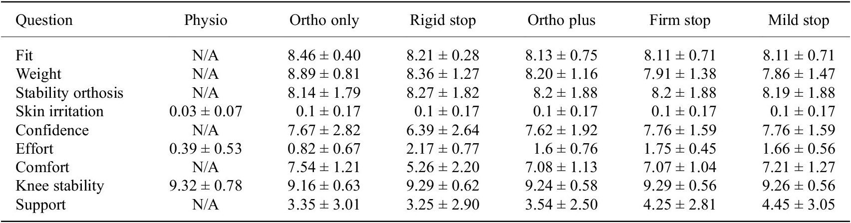
The questionnaire was analyzed descriptively (Table 6). Fit, orthosis stability, and knee stability were rated positively across conditions. The rigid stop showed the least favorable descriptive pattern, with lower comfort and confidence and higher perceived effort than the motor-only and soft-stop conditions. Ratings for the firm and mild soft stops were generally close to those for ortho plus.
Results of questionnaire (mean
$ \pm $
 standard deviation)

Table 6. Long description
Means in the order ortho only, rigid stop, ortho plus, firm stop, mild stop (standard deviations are given in the table; physio only where applicable). Fit: 8.46, 8.21, 8.13, 8.11, 8.11. Weight: 8.89, 8.36, 8.20, 7.91, 7.86. Stability orthosis: 8.14, 8.27, 8.2, 8.2, 8.19. Skin irritation: physio 0.03; 0.1 in all orthosis conditions. Confidence: 7.67, 6.39, 7.62, 7.76, 7.76. Effort: physio 0.39; 0.82, 2.17, 1.6, 1.75, 1.66. Comfort: 7.54, 5.26, 7.08, 7.07, 7.21. Knee stability: physio 9.32; 9.16, 9.29, 9.24, 9.29, 9.26. Support: 3.35, 3.25, 3.54, 4.25, 4.45.
Overall, participants rated the fit and stability of the orthosis positively across all conditions, with high mean scores exceeding
$ 8.0 $
 with a slight decline observed with the added motion limits and the motor unit. Similarly, the perceived influence of orthosis weight on task performance was rated favorably. The addition of the motor and soft stops reduced ratings slightly to
$ 7.91 $
 (firm) and
$ 7.86 $
 (mild). Notably, even the rigid stop condition (
$ 8.36 $
 ) exhibited a small reduction compared to the ortho-only configuration. Participants reported high confidence in the orthosis across most configurations, with mean ratings between
$ 7.62 $
 and
$ 7.76 $
 . The rigid stop condition, however, resulted in a noticeably lower mean confidence score of
$ 6.39 $
 . Regarding perceived effort during walking, participants reported values close to zero for the physiological condition. Although effort remained low overall, it increased slightly with the addition of the orthosis, limits, and motor. The mild and firm soft stop configurations yielded mean scores of
$ 1.66 $
 and
$ 1.75 $
 , respectively, which closely resembled the ortho plus condition (
$ 1.6 $
 ). In contrast, the effort during rigid stop configuration was rated as notably higher (
$ 2.17 $
 ). A similar trend was observed for perceived comfort. While comfort remained relatively high across conditions, ranging between
$ 7.07 $
 and
$ 7.54 $
 for the firm stop and ortho-only conditions, the rigid stop configuration again stood out with a notably lower mean comfort score of
$ 5.26 $
 . Despite differences in comfort and effort, participants consistently rated the feeling of knee stability as high across all conditions, with mean scores ranging from
$ 9.16 $
 to
$ 9.32 $
 . In contrast, perceived support from the orthosis itself remained comparatively low, with means between
$ 3.25 $
 (rigid stop) and
$ 4.45 $
 (mild stop).
4. Discussion
This study investigated whether a virtual impedance “soft stop” controller, implemented in a powered knee orthosis, can limit terminal swing knee flexion without substantial kinematic adaptations or muscular demands compared to rigid mechanical stops.
4.1. Effectiveness of impedance soft stops in limiting knee flexion
In this healthy cohort, both impedance presets constrained terminal swing knee flexion at clinically relevant angles. The firm preset imposed comparatively stricter bounds (
$ {q}_{95}={37.1}^{\circ } $
 ), whereas the mild preset achieved flexion limits of (
$ {q}_{95}={44.6}^{\circ } $
 ) close to the planned (
$ {45}^{\circ } $
 ) target while preserving additional headroom below the mechanical
$ {60}^{\circ } $
 stop. Peak resisting torques remained modest (peak:
$ \sim 14\;\mathrm{N}\;\mathrm{m} $
 for firm,
$ \sim 4\;\mathrm{N}\;\mathrm{m} $
 for mild), substantially below typical peak physiological knee flexion moments, indicating that the soft-stop controller can impose a robust flexion boundary without overloading the actuator or the user.
Secondary compensatory kinematic changes were generally small under the soft limits, whereas the rigid stop produced the greatest reduction in ankle push-off ROM and the highest right-biceps-femoris ARV. The controller schedules stiffness and damping selectively near the flexion boundary, gated by both angle and velocity. This strategy engages braking only while the knee approaches the flexion boundary and distributes deceleration over a broader angular interval near the prescribed boundary, thereby reducing abrupt end-stop interaction. This increases the braking excursion, reducing the angular-mean resisting torque required to remove that energy from the brace-limb interaction. ACL or graft loading was not measured and cannot be inferred from actuator torque alone, because ligament loading also depends on knee angle, combined external loading, muscle forces, and tibiofemoral kinematics (Markolf et al., Reference Markolf, Burchfield, Shapiro, Shepard, Finerman and Slauterbeck1995). The observed biceps femoris EMG patterns, lower mean and
$ {q}_{95} $
 ARV with both soft-stop presets than with the rigid stop, are consistent with this interaction pattern. Peak timing, however, differed between the two presets. The mild stop remained close to physiological gait, whereas the firm stop was similar to the rigid stop. Moreover, the preserved extension velocities near baseline during terminal swing were consistent with the controller’s ability to swiftly release extension movement while reliably restricting flexion.
Subjective evaluation of the orthosis revealed that both the added motor weight and the imposed knee flexion limits influenced participants’ perceptions of fit and comfort. Participants reported a moderate increase in perceived effort when wearing the orthosis alone, which further increased with the addition of the motor in the ortho plus condition. Notably, the rigid-stop condition elicited an even higher perception of effort than ortho plus. While induced gait constraints are known to induce compensatory movements that elevate energy expenditure, the rigid-stop condition also produced an increased perception of weight relative to orthosis only, even though no additional mass was present. This suggests that the rigid flexion limitation itself contributed to the perceived burden, as also reflected in the lower comfort and confidence ratings. In contrast, the impedance-based soft-stop configurations, although also limiting knee flexion, did not produce comparably strong effects. Across most subjective categories, the soft-stop conditions closely aligned with ortho plus, indicating that impedance-based limits were perceived as less intrusive. While inducing minor weight effects, they appear to mitigate the negative perceptions associated with rigid stops and offer a less intrusive alternative to rigid mechanical constraints.
4.2. Relation to prior work
Mechanical soft-stop mechanisms for knee braces have been described in patents (Kirchner et al., Reference Kirchner, Phillips and Bounardjian2005) and partially realized in products or prototype studies, but their practical implementation remains limited. Notably, existing commercial braces predominantly integrate a soft limit in knee extension rather than flexion (DonJoy, 2025), which does not directly address configurable flexion limiting during walking. Previous attempts to integrate flexion-bound soft stops using elastomer components have reported improved user comfort compared to rigid stops, but have also encountered reliability issues, with mechanical parts failing under repeated flexion loading (Greenfield et al., Reference Greenfield, Hwang, Davies and McDaid2017).
In parallel, active orthoses and exoskeletons have demonstrated the value of impedance modulation and state-dependent control for assisting gait. These systems typically focus on augmentation or extension assistance and on reducing metabolic cost, rather than implementing tunable virtual soft stops at configurable flexion bounds in a brace-like form factor. As a result, there remains little quantitative evidence on how software-defined soft limits perform relative to conventional rigid mechanical stops in the specific context of ACL-oriented flexion restriction during walking.
Our work is therefore best viewed as an application-focused extension of this prior literature. We build on established proportional-derivative control and impedance-shaping concepts to introduce a tunable, angle- and velocity-gated soft-stop controller in a powered knee orthosis and evaluate it head-to-head against a conventional rigid stop and orthosis-only baselines. By quantifying effects on joint kinematics, biceps-femoris activity, and subjective user experience in healthy adults, we demonstrate the practical feasibility and potential benefits of software-defined soft stops for limiting knee flexion while inducing comparatively few compensatory adjustments.
From a clinical perspective, functional ACL bracing is intended to mitigate several injury-relevant mechanisms, but the available biomechanical and clinical evidence remains heterogeneous, particularly for dynamic, high-risk activities (Heyworth et al., Reference Heyworth, Berube, Gossman, Milewski and Bixby2025). A reduction in knee flexion ROM is not inherently desirable across all rehabilitation stages. In later recovery phases, restoration of full and symmetrical ROM becomes a core objective, and prolonged unnecessary motion restriction could hinder recovery (Wilk et al., Reference Wilk, Macrina, Cain, Dugas and Andrews2012; Cavanaugh and Powers, Reference Cavanaugh and Powers2017). The present controller is therefore intended as a temporary, clinician-tunable strategy for phases in which a flexion bound has already been prescribed. Its software-defined nature allows the constraint to be progressively relaxed or removed as rehabilitation advances without changing hardware. Relative to a rigid stop, the soft-stop concept distributes deceleration over a broader angular interval and avoids abrupt end-stop interaction. In the present data, this was associated with lower terminal swing biceps femoris activity and smaller compensatory kinematic changes than the rigid-stop condition. However, the present healthy-adult data do not establish clinical efficacy after ACL reconstruction. Notably, brace-related adaptations observed in controlled walking assessments do not necessarily generalize to more demanding tasks such as running, underscoring the importance of task-specific evaluation (Heyworth et al., Reference Heyworth, Berube, Gossman, Milewski and Bixby2025). Our study therefore provides a controlled, instrumented baseline evaluation of how rigid and impedance-based range limits shape kinematics, muscle activity, and perceived comfort during walking.
4.3. Implications, limitations, and future work
The proposed impedance-based soft-stop controller offers several practical advantages for intelligent knee orthoses. First, the controller provides tunable, angle- and velocity-gated braking near the configured flexion boundary, allowing the preset strength to be adjusted without changing the underlying hardware. Second, the modest peak torques observed in our experiments (on the order of a few
$ \mathrm{N}\;\mathrm{m} $
 ) suggest that relatively small actuators and power supplies are sufficient, although the firm-stop value of
$ 14.55\;\mathrm{N}\;\mathrm{m} $
 shows that actuator sizing must account for peak demand as well. From a hardware perspective, the soft-stop behavior is achieved in software using the existing actuator and encoder. No additional sensors or complex mechanical elements are required, so the incremental hardware cost relative to a powered orthosis without soft stops is minimal. Third, compared with the rigid mechanical stop, the soft-stop presets showed lower right-biceps-femoris ARV, preserved more ankle push-off ROM, and induced only small proximal kinematic changes. Together with the questionnaire results, which showed that the rigid stop was perceived as less comfortable, more effortful, and associated with lower confidence than the soft-stop and motor-only conditions, these findings suggest that virtual soft stops can enforce flexion limits with a less intrusive interaction for the user. These user-perceived differences may be clinically relevant because adherence to brace wear is often limited by comfort- and usability-related factors. Whether the softer interaction improves acceptance or sustained use should be tested in postoperative populations.
Yet, several limitations should be considered when interpreting these findings. The study sample consisted exclusively of healthy, young adults walking at a fixed pace on a treadmill. This pilot was intended as an initial feasibility and interaction study before progression to postoperative populations. We did not directly measure ACL/graft strain, joint contact forces, rigid-stop contact impulse, brace-limb interface forces, metabolic cost, or long-term adaptation. Therefore, the results cannot be directly generalized to patients after ACL reconstruction or to community ambulation in more complex environments. The prototype orthosis, although based on a commercial brace, still exhibited additional weight and bulk compared with standard passive braces. Further mechanical integration and optimization would be required for long-term clinical deployment.
Future work should therefore focus on (i) extending the evaluation to ACL-reconstruction patients and other clinical populations, (ii) developing patient-specific tuning algorithms that gradually relax flexion limits based on objective progress indicators, and (iii) integrating real-time monitoring of motor position, velocity, and torque into rehabilitation dashboards that can support clinician decision-making. In parallel, long-term durability testing and comparative studies against passive soft-stop mechanisms would help clarify when virtual soft stops, mechanical stops, or hybrid designs offer the best trade-offs between safety, comfort, and system complexity. In addition, future evaluations should incorporate sensorimotor and neurocognitive outcomes. Follow-up studies should combine gait and EMG outcomes with proprioception, reactive balance, confidence, and performance during faster walking, uneven-ground locomotion, and sport-relevant tasks.
5. Conclusion
In this pilot study with healthy adults, an angle- and velocity-gated, gain-scheduled PD soft-stop controller integrated into a powered knee orthosis significantly limited swing-phase knee flexion and reduced flexion velocity with moderate resisting torques and small compensatory kinematic changes. The mild preset produced a less restrictive bound near
$ {45}^{\circ } $
 , whereas the firm preset provided stronger limitation. The trial-mean participant-random-intercept LMM identified lower right-biceps-femoris ARV with both soft-stop presets than with the rigid stop. Overall, the results demonstrate the technical feasibility and practical configurability of software-defined soft stops in a powered knee orthosis; clinical performance after ACL reconstruction remains to be evaluated.
Supplementary material
The supplementary material for this article can be found at http://doi.org/10.1017/wtc.2026.10051.
Data availability statement
Data can be made available to interested researchers upon request by email to the corresponding author.
Acknowledgments
The authors thank the study participants and OT Baßler GmbH, Erlangen, for their support of this research through expert knowledge and orthopedic equipment. We acknowledge the use of large language models for assistance in language editing and text refinement. All content and claims remain the responsibility of the authors.
Authorship contributions
Conceptualization: M.-A.S., M.B., C.C.; Data curation: M.-A.S., K.S., O.U.; Data visualization: M.-A.S., K.S., O.U.; Methodology: M.-A.S., K.S.; Writing original draft: M.-A.S., K.S. All authors approved the final submitted draft.
Funding statement
This work was partially supported by the German Federal Ministry of Education and Research (BMBF) under the Robotics Institute Germany (RIG) and through the project AutoAssist (grant number 13GW0716B).
Competing interests
The authors declare no competing interests exist.
Ethical standards
The authors assert that all procedures contributing to this work comply with the ethical standards of the relevant national and institutional committees on human experimentation and with the Declaration of Helsinki of 1975, as revised in 2008. The study protocol was approved by the Ethics Commission at the Faculty of Medicine at Friedrich-Alexander-Universität Erlangen-Nürnberg (approval no. 23-350-B). All participants provided written informed consent before participation.














 Open access

