Introduction
Lithium-ion batteries (LIBs), which have high energy density, superior rate capability, and excellent cycling performance, are successfully applied to electronic devices or electronic parts used in automobile, hybrid electric vehicles, and aircraft [Reference Nam, Kim, Yoo, Chiang, Meethong, Hammond, Chiang and Belcher1, Reference Mukhopadhyay and Sheldon2, Reference Goodenough and Kim3]. Recently, alloy materials have been developed as promising candidates for electrodes because of their high specific capacity in LIBs [Reference Zhang4, Reference Edfouf, Cuevas, Latroche, Georges, Jordy, Hézèque, Caillon, Jumas and Sougrati5]. For example, Si exhibits high theoretical specific capacity (4200 mA h/g) and Sn (993 mA h/g), which are more than the commercialized graphite anodes (372 mA h/g) [Reference Obrovac, Christensen, Le and Dahnb6]. Unfortunately, large stress is generated during the lithiation for the high-capacity electrode driven by volume expansion, resulting in the fracture of the electrode, which limited the application of high-capacity electrodes in LIBs [Reference Liu, Zheng, Zhong, Huan, Karki, Zhang, Liu, Kushima, Liang, Wang, Cho, Epstein, Dayeh, Picraux, Zhu, Li, Sullivan, Cumings, Wang, Mao, Ye, Zhang and Huang7, Reference Zhao, Pharr, Vlassak and Suo8, Reference Huggins and Nix9]. Therefore, it is particularly significant to investigate the structural evolution and mechanical mechanism of high-capacity electrodes.
Obviously, fracture phenomena of electrode materials caused by diffusion-induced stress are a major influencing factor in lithium-ion batteries [Reference Lee, Lee, Ryu, Nix, Gao and Cui10, Reference ChiuHuang and Huang11, Reference Lee, McDowell, Berla, Nix and Cui12]. Therefore, many works have devoted to explore the stress and crack propagation mechanisms in nanoelectrode, including theoretical models [Reference Weng, Zhou and Cai13, Reference Wei and Yan14, Reference Hu, Zhao, Cai and Zhou15, Reference Bhandakkar and Gao16] and experimental observations [Reference Liu and Huang17, Reference Gu, Yang, Perea, Zhang, Zhang and Wang18, Reference Ye, Shi, Cai, Lee and He19]. Chen et al. investigated the stress intensity factor (SIF) evolution by an established crack propagation model of spherical electrode nanoparticles [Reference Chen, Zhou and Cai20]. And Guduru et al. found that in-plane cracking of the silicon thin film electrode should mainly occur in the delithiation stage. Because of the plastic deformation, there is a large tensile stress in the film during delithiation, thus leading to the breakage of the electrode [Reference Chon, Sethuraman, McCormick, Srinivasan and Guduru21]. Li et al. investigated the dislocation effect on diffusion-induced stress in a cylindrical electrode and demonstrated that dislocation stress can decrease diffusion-induced stress (DIS) and suppress the crack nucleation [Reference Li, Fang, Liu and Liu22]. Lee et al. revealed that the electrode cracking was related to the size of the electrode [Reference Lee, Ryu, Nix and Cui23]. According to their analyses, the critical size of the Si anode was 300 nm, which was in good agreement with experimental results [Reference Liu, Zhong, Huang, Mao, Zhu and Huang24]. Hao et al. found that the surface stress can reduce maximum tensile stress, which may become a resistance to brittle fracture [Reference Hao, Gao and Fang25]. Xu et al. investigated the stress evolution for the cylindrical electrode under bending deformation and phase transformation. The results revealed that the crack does not spread under the superposition of the diffusion stress and the bending stress [Reference Xu, Weng, Ji and Zhou26]. Gao et al. found that the operation at higher concentrations is an effective means to minimize fracture of the electrode [Reference Gao and Zhou27]. Although these analytic works have studied the diffusion-induced stress and fracture phenomenon for the electrode materials, including the appearance of the diffusion coefficient [Reference Zhang, Li and Zheng28], plastic deformation [Reference Chen, Fan, Hong, Chen, Ji, Zhang, Zhu and Chen29], and reaction rate [Reference Liu, Zhou, Chen and Zhu30], greatly effective reduction of DIS and improved fracture resistance of the electrode remain poorly understood.
Recently, Wang et al. observed the maximum size of ∼526 nm Sn particles without cracking during lithiation because this desirable behavior of Sn is mainly attributed to the creep relaxations [Reference Wang, Fan, Liu, Jungjohann, Lee, Mao, Liu and Zhu31]. These results indicated that the size of Sn critical is far greater than Si critical (300 nm). Creep deformation can effectively reduce the DIS and prevent crack propagation using experimental observation and numerical simulation [Reference Chen, Xuan and Tu32, Reference Boles, Thompson, Kraft and Monig33]. Therefore, diffusion-induced creep is an important mechanism for stress relaxation in lithium-ion batteries. Qaiser et al. simulated the effect of creep relaxation on the fracture of Sn micro pillars, and Lu et al. established a new model to estimate the effect of creep deformation in the film/substrate system during lithiation [Reference Qaiser, Yong, Hong and Han34, Reference Lu, Qi, Xu, Wang and Xiang35]. Although these analytic works have studied the creep relaxation of electrode materials during lithium insertion, few research studies have been carried out to investigate the mechanisms of creep deformation and fracture with creep of spherical nanoelectrodes for lithium-ion batteries.
To gain insight into the mechanisms of creep deformation and their effects on the diffusion-induced stress in the electrode during lithiation, it is indispensable to actualize the systematic investigation on its mechanical model. Herein, the Sn electrode we chose is considered to be representative, and the theoretical model of the creep deformation effect is established. We analyzed the effect of surface stress, electrode size, and dimensionless time on creep deformation under galvanostatic operation and potentiostatic operation in detail. Finally, the safe zones, which cannot fracture for the electrode with creep deformation, are obtained. Our results illustrate the mechanisms of creep deformation on the electrode and provide a valuable mechanical model to improve the understanding of deformation in the electrode during lithiation.
Theoretical model
Concentration distribution
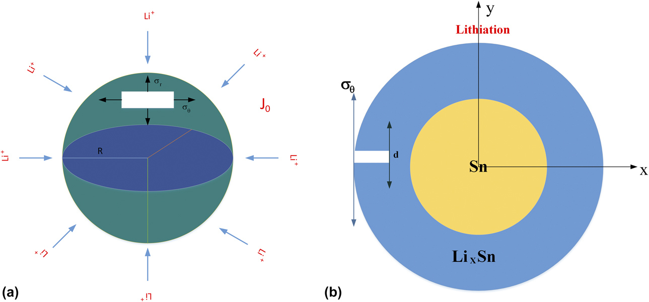
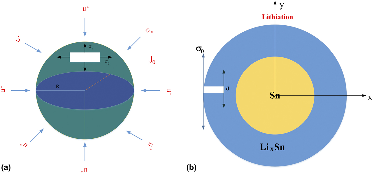
As we have known, Li ions gradually diffuse from the surface of the electrode material to the inside of the material during lithiation. Figure 1(a) shows the Sn particle electrode model, which is applied to analyze the Li-ion concentration; R represents the radius of the Sn particle electrode.
(a) Schematic of lithium ion intercalation electrode and produced diffusion-induced stress in the spherical particle during lithiation. (b) Projection of the x–y plane of the pre-existing semielliptical surface crack in a spherical electrode.
A sphere electrode suffers insertion/extraction of Li ions. Supposing the deformation is quasistatic, the transport of lithium ions in the electrode is a time-dependent concentration-driven diffusion process. According to the diffusion equation, the solute transport in the particle electrode is established. The concentration gradient along the radial direction can be expressed as follows:
 $${{\partial c} \over {\partial t}} = D{\nabla ^2}C = D\left( {{{{\partial ^2}c} \over {{\partial ^2}r}} + {1 \over r}{{\partial c} \over {\partial r}}} \right)\quad ,$$
where D denotes the diffusion coefficient of Li ions.
Under galvanostatic operation, the boundary conditions can be expressed as [Reference Deshpande, Cheng and Verbrugge36].
 $${\left. {C\left( {r,0} \right)} \right|_{0 \le r \le R}} = {C_0},D{\left. {{{\partial c} \over {\partial r}}} \right|_{r = 0}} = 0, - D{\left. {{{\partial c} \over {\partial r}}} \right|_{r = R}} = - {I \over F}\quad ,$$
where C 0 is the initial solute concentration, I is the recharging current, and F represents the Faraday constant, the value is 96,486.7 C/mol.
Using the diffusion equation in Eq. (1) with initial and boundary conditions in Eq. (2), the solute concentration distribution during insertion is given as follows:
 $${{C\left( {r,t} \right) - {C_0}} \over {{{IR} / {FD}}}} = {{{\psi ^2}} \over 2} + 2\varphi - {1 \over 4} - 2\sum\limits_{n = 1}^\infty {{{{J_0}\left( {\psi {\lambda _n}} \right)\;{\rm{exp}}\;\left( { - \varphi \lambda _n^2} \right)} \over {\lambda _n^2{J_1}\left( {{\lambda _n}} \right)}}} \quad ,$$
where ψ = r/R and φ = Dt/R 2. J 1 denotes the Bessel function of the first kind, and λn is the root of J 1(λn).
Under potentiostatic operation, the initial and boundary conditions can be expressed as [Reference Wong, Chan and Yue37].
 $${\left. {C\left( {r,0} \right)} \right|_{0 \le r \le R}} = {C_0},C\left( {r,t} \right) = {C_R},C\left( {0,t} \right) = {\rm{finite}}\quad ,$$
where C 0 represents initial solute concentration in the sphere particle and C R is the maximum stoichiometric Li concentration.
Using the diffusion equation in Eq. (1) with initial and boundary conditions in Eq. (4), the solute concentration distribution during insertion is given as follows:
 $${{C\left( {r,t} \right) - {C_0}} \over {{C_R} - {C_0}}} = 1 - {\varphi \over 4}\sum\limits_{n = 1}^\infty {{{{J_1}\left( {\psi {\lambda _n}} \right)\;\exp \;\left( { - \varphi \lambda _n^2} \right)} \over {\lambda _n^2{J_1}\left( {{\lambda _n}} \right)}}} \quad .$$
Stress distribution
As shown in Fig. 1(a), a symmetrical particle electrode with a diameter 2R is suffering a flux of lithium ions from the surface. The stress state can be represented by (σr, σθ, σθ), where σr and σθ are the radial and hoop stresses, respectively. The stress field during lithiation and delithiation can be solved by an isotropic and linearly elastic model. By the analogy to thermal stress, the constitutive relationship in a sphere coordinate system (r, θ, φ) is [Reference Timoshenko, Goodier and Abramson38].
 $${\varepsilon _{\rm{r}}} = {1 \over E}\left( {{\sigma _{\rm{r}}} - 2\nu {\sigma _\theta }} \right) + {1 \over 3}\Omega C\left( {r,t} \right)\quad ,$$
 $${\varepsilon _\theta } = {1 \over E}\left[ {\left( {1 - \nu } \right){\sigma _\theta } - \nu {\sigma _{\rm{r}}}} \right] + {1 \over 3}\Omega C\left( {r,t} \right)\quad .$$
where E is the Young’s modulus, ν is the Poisson’s ratio, Ω is the volume expansion coefficient of per mole solute atoms, and C is the molar concentration of the lithium ion, respectively.
Assuming that deformation of the anode material is infinitely small, the radial and tangential strains can be expressed as functions of displacement given as follows:
 $${\varepsilon _{\rm{r}}} = {{{\rm{d}}u} \over {{\rm{d}}r}},{\varepsilon _\theta } = {u \over r}\quad .$$
Because of the fact that elastic deformation is much smaller than atom diffusion on the same characteristic time, charging and discharging processes are static equilibrium. Taking no account of body force, the mechanical balance equation of a spherical electrode can be expressed as follows:
 $${{{\rm{d}}{\sigma _{\rm{r}}}} \over {{\rm{d}}r}} + 2{{{\sigma _{\rm{r}}} - {\sigma _\theta }} \over r} = 0\quad .$$
The radial displacement u of the sphere particle electrode is given by the following equation:
 $$u = {{1 + \nu } \over {1 - \nu }}{\Omega \over 3}{1 \over {{r^2}}}\int_0^r {C{r^2}{\rm{d}}r} + Ar + {B \over {{r^2}}}\quad ,$$
where A and B are integral constants. Their values were obtained by boundary condition of the sphere electrode σr|r = 0 = constant, σr|r = R = 0.
By applying the Eqs. (4)–(8), the stress distribution in the sphere can be obtained as follows:
 $${\sigma _{\rm{r}}}\left( {r,t} \right) = {{2E\Omega } \over {3\left( {1 - \nu } \right)}}\left[ {{1 \over {{R^3}}}\int_0^R {{r^2}C\left( {r,t} \right){\rm{d}}r} - {1 \over {{r^3}}}\int_0^r {{r^2}C\left( {r,t} \right){\rm{d}}r} } \right]\quad ,$$
 $$\scale 82%{{\sigma _\theta }\left( {r,t} \right) = {{2E\Omega } \over {3\left( {1 - \nu } \right)}}\left[ {{1 \over {{R^3}}}\int_0^R {{r^2}C\left( {r,t} \right){\rm{d}}r} - {1 \over {2{r^3}}}\int_0^r {{r^2}C\left( {r,t} \right){\rm{d}}r} - {1 \over 2}C\left( {r,t} \right)} \right]\quad .$$
The evolution of the stress on the electrode during lithiation may be evaluated by establishing a diffusion stress model of the nanoparticle in the elastic deformation stage.
Creep deformation
The researchers have found that electrode materials induce creep deformation which is caused by the diffusion-induced stress of the electrodes during lithiation. For primary and stationary creep regime, the inelastic diffusion stress-creep strain of the active materials is governed by the well-known Norton power-law model [Reference Kang, Kang, Han, Kim, Lee, Cho and Cho39].
 $${\varepsilon _{{\rm{cr}}}} = {\rm{sign}}\left( {{\sigma _{\rm{e}}}} \right)M{\left| {{\sigma _{\rm{e}}}} \right|^n}\quad ,$$
where M and n are creeps constant and stress exponent, respectively. We assume that the stress of generating creep is the average stress of the spherical electrode. Because the spherical particle is symmetrical, effective stress σe can be expressed as follows:
 $$\scale 94%{{\sigma _{\rm{e}}} = {\sigma _{{\rm{mean}}}} = {{{\sigma _{\rm{r}}} + 2{\sigma _{\rm{\theta }}}} \over 3} = {{2E\Omega } \over {3\left( {1 - \nu } \right)}}\left[ {{1 \over {{R^3}}}\int_0^R {{r^2}C\left( {r,t} \right){\rm{d}}r} - {{C\left( {r,t} \right)} \over 3}} \right]\quad .$$
According to the mechanical equilibrium conditions, when considering creep deformation, for linear elasticity model, the stress–strain relationship can be expressed as follows:
 $${\varepsilon _{\rm{r}}} - {\varepsilon _{\rm{t}}} - {\varepsilon _{{\rm{cr}}}} = {1 \over E}\left( {{\sigma _{\rm{r}}} - 2\nu {\sigma _\theta }} \right){\rm{\ and}}$$
 $${\varepsilon _{\rm{r}}} - {\varepsilon _{\rm{t}}} - {\varepsilon _{{\rm{cr}}}} = {1 \over E}\left[ {\left( {1 - \nu } \right){\sigma _\theta } - \nu {\sigma _{\rm{r}}}} \right]\quad .$$
For the strain gradient plastic J 2 flow model, the constitutive relations can be described as follows:
 $$\varepsilon = {\varepsilon ^{\rm{e}}} + {\varepsilon ^{\rm{p}}}\quad ,$$
where εe is the elastic strain tensor and εp is the plastic strain tensor.
 $${\varepsilon ^e} = M{\rm{:}}\sigma \quad ,$$
where M is the elastic compliance tensor, which can be written as follows:
 $${M_{xyzn}} = {{1 + \nu } \over E}\left( {{\delta _{xz}}{\delta _{yn}} - {\nu \over {1 + \nu }}{\delta _{xy}}{\delta _{zn}}} \right)\quad ,$$
where ν is the Poisson’s ratio, E is the Young’s modulus, δxy is the Kronecker’s delta.
The plastic strain tensor εp is proportional to the deviatoric stress tensor σd given as follows:
 $${\varepsilon ^p} = {{3{\varepsilon ^p}} \over {2{\sigma _{\rm{d}}}}}{{\boldsigma }_{\rm{d}}}\quad ,$$
where  ${\sigma _{{{\rm{d}}_{xy}}}} = {{{\sigma _{xy}} - {\sigma _{zz}}{\delta _{xy}}} / 3}$ and
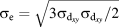 ${\sigma _{\rm{e}}} = \sqrt {{{3{\sigma _{{{\rm{d}}_{xy}}}}{\sigma _{{{\rm{d}}_{xy}}}}} / 2}}$ is the Von Mises stress.
The equivalent plastic strain εp can be obtained by the power law given as follows:
 $${\varepsilon ^{\rm{p}}} = \varepsilon {\left( {{{{\sigma _{\rm{e}}}} \over {{\sigma _{{\rm{flow}}}}}}} \right)^m}\quad ,$$
where 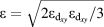 $\varepsilon = \sqrt {{{2{\varepsilon _{{{\rm{d}}_{xy}}}}{\varepsilon _{{{\rm{d}}_{xy}}}}} / 3}}$ is the equivalent strain and
 ${\varepsilon _{{{\rm{d}}_{xy}}}} = {{{\varepsilon _{xy}} - {\varepsilon _{zz}}{\delta _{xy}}} / 3}$ is the deviatoric strain, M is the rate-sensitivity exponent, and σflow is the flow stress.
By establishing a mechanical equilibrium, the total strain caused by the volume change in the lithiated material can be expressed as [Reference Zhu, Zhou, Chen, Liu and Liu40].
 $${\varepsilon _{\rm{t}}} = {\rm{ln}}\left( {1 + {\varepsilon _{\rm{e}}}} \right) = {{\Omega C\left( {r,t} \right)} \over 3}\quad .$$
There, the stress equation containing creep deformation can be obtained as follows:
 $$\scale 98%{{\sigma '_{\rm{r}}} = {E \over {\left( {1 - 2{\rm{\nu }}} \right)\left( {1 + {\rm{\nu }}} \right)}}\left[ {{\rm{\nu }}{{{\rm{d}}u} \over {{\rm{d}}r}} + {u \over r} - \left( {1 + {\rm{\nu }}} \right)\left( {{{\Omega C\left( {r,t} \right)} \over 3} + {\varepsilon _{{\rm{cr}}}}} \right)} \right]\quad {\rm{,}}$$
 $$\scale 85%{{\sigma '_\theta } = {E \over {\left( {1 - 2\nu } \right)\left( {1 + \nu } \right)}}\left[ {\left( {1 - \nu } \right){{{\rm{d}}u} \over {{\rm{d}}r}} + 2{\rm{\nu }}{u \over r} - \left( {1 + {\rm{\nu }}} \right)\left( {{{\Omega C\left( {r,t} \right)} \over 3} + {\varepsilon _{{\rm{cr}}}}} \right)} \right]\quad ,$$
where  $u = {{1 + {\rm{\nu }}} \over {1 - {\rm{\nu }}}}{\Omega \over 3}{1 \over {{r^2}}}\int_0^r {C\left( {r,t} \right)} {r^2}{\rm{d}}r + Ar + {B \over {{r^2}}}$, A and B are the integral constants, and their value can be obtained by the following boundary conditions: (1) u|r = 0 = 0; (2) u|r = R = 0.
Through the coupling of DIS and diffusion-induced creep, the evolution of stress dependent on time can be obtained.
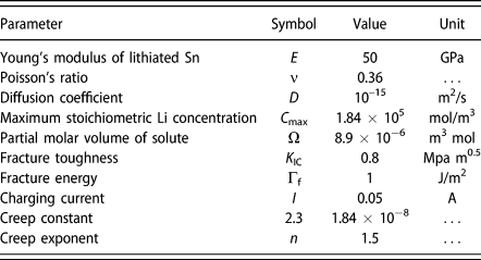
The values of all parameters are in the table in Table I.
Material properties and operating parameters.

Fracture
Introducing the SIF, a fracture model is established to analyze the influence of stress with creep deformation for the crack propagation. And the schematic diagram of the model is shown in Fig. 1(b). We assume that the SIF value is only at the deepest point of the crack, and pre-crack length is much smaller than the particle radius. Besides, the SIF of the I crack tip is approximately equal to the SIF of the surface. When the maximum SIF value exceeds the inherent fracture toughness value of the material, the surface crack will propagate.
According to the approach of Mattheck [Reference Mattheck, Munz and Stamm41], we use the weight function method to analyze the SIF for a symmetric loading on an elastic system. Thus, the SIF can be written as follows:
 $${K_{\rm{I}}} = {E \over {{K^{{\rm{ref}}}}\left( {1 - {{\rm{\nu }}^2}} \right)}}\int_0^d {{{\sigma '}_\theta }} \left( x \right)m\left( {x,d} \right){\rm{d}}x\quad ,$$
where K ref is the reference SIF of the system, which is defined as 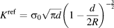 ${K^{{\rm{ref}}}} = {\sigma _0}\sqrt {\pi d} {\left( {1 - {d \over {2R}}} \right)^{ - {3 \over 2}}}$,
 ${{\rm{\sigma '}}_{\rm{\theta }}}\left( x \right)$ indicates a tangential load with creep deformation perpendicular to the surface of the crack, x = R − r is a variable, m(x, d) is the weight function, and more details are given in the Supplementary material. An essential feature of Eq. (18) is that the stress distribution is integrated over the entire crack length. To generate a large SIF, the DIS must be large at the crack tip, not just at the particle surface. Hence, we can get the SIF for an edge crack on the surface as follows:
 $${K_{\rm{I}}} = \sqrt {{R \over {\pi b}}} \int_0^b {\sum\limits_{n = 1}^5 {{{\sigma '}_\theta }\left( {x,t} \right)} } {\gamma _n}\left( b \right){\left( {1 - {\psi \over b}} \right)^{n - {3 \over 2}}}{\rm{d}}x\quad ,$$
where the dimensionless parameters expressed are ψ = r/R and b = d/R.
The fracture toughness of the electrode material is K IC, once the SIF exceeds K IC, the growth of pre-cracks could not stop until the electrode material is broken. In addition, mode II and III crack face loading is neglected because the material’s other toughness values are generally much larger than K IC. To deeply calculate, the dimensionless SIF is given by the following equation:
 $${\hat{K}_{\rm{I}}} = {{{K_{\rm{I}}}} \over {{{E\Omega } \over {3\left( {1 - \nu } \right)}}\left( {{{I{R^{\vskip -3pt{3 \over 2}}}} \over {FD}}} \right)}}\quad .$$
We further calculate the critical size of the electrode under the coupling DIS and diffusion-induced creep. The reduction in the elastic energy associated with a crack advancing a unit area defines the energy rate G m. The driving force for the propagation of a pre-existing crack in a spherical particle of the radius r a should take the form
 $${G_{\rm{m}}} = Z{{\sigma _{\rm{Y}}^2} \over {{E_{\rm{b}}}}}{r_{\rm{R}}}\quad ,$$
where E b is the Young’s modulus of the Lix Sn, Z is a dimensionless parameter determined using the elastic boundary conditions, and in the case of a channel crack in the surface of the electrode, Z = 2 is an experience value [Reference Ma, Xie, Wang, Zhang, Pan, Zhou and Lu42]. σY is yield strength of the Sn anode material.
The fracture energy of the particle electrode is Γf, which is express as  ${\Gamma _{\rm{f}}} = {{K_{{\rm{IC}}}^2} / {{E_{\rm{b}}}}}$. Therefore, the critical particle size
 $r_{\rm{R}}^{{\rm{cr}}}$ can be determined by [Reference Wu, Xie, Wang, Lu and Ma43].
 $$r_{\rm{R}}^{{\rm{cr}}} = {{K_{\rm{I}}^2} \over {Z\sigma _{\rm{Y}}^2}}\quad .$$
The fracture of particles will not occur if the designed electrode size is smaller than the critical size. In other words, that is, the fracture is avoided if the particle strength is small yield strength of lithiated tin.
Results and discussion
Galvanostatic operation
Diffusion concentration with creep deformation
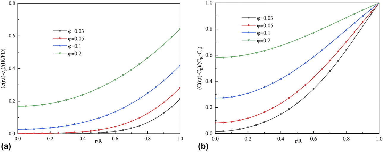
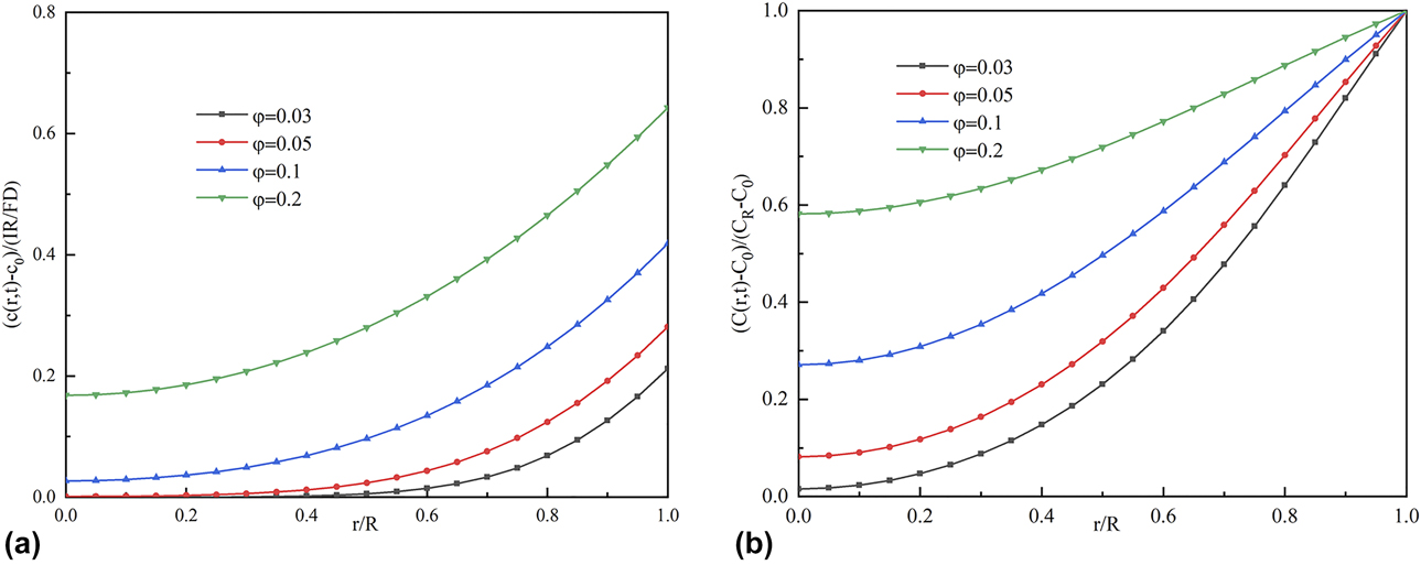
As shown in Fig. 2(a), Li ions are gradually transferred from the surface of the active material to the center driven by the concentration gradient under galvanostatic operation. As dimensionless time increases, lithium-ion concentration monotonically increases in the same position. The concentration in the center of the spherical particles is the smallest and reaches the maximum at the surface of the electrode particles. It is known that inhomogeneous concentration distribution produces stress during lithiation.
(a) Profile of the solute concentration in the spherical electrode at various dimensionless times during lithium insertion under galvanostatic operation. (b) Profile of the solute concentration in the spherical electrode at various dimensionless times during lithium insertion under potentiostatic operation.
Stress distribution with creep deformation
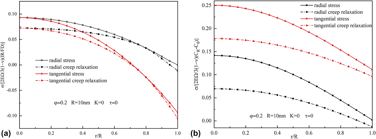
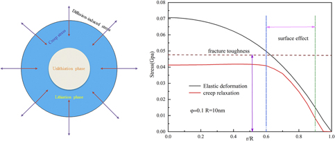
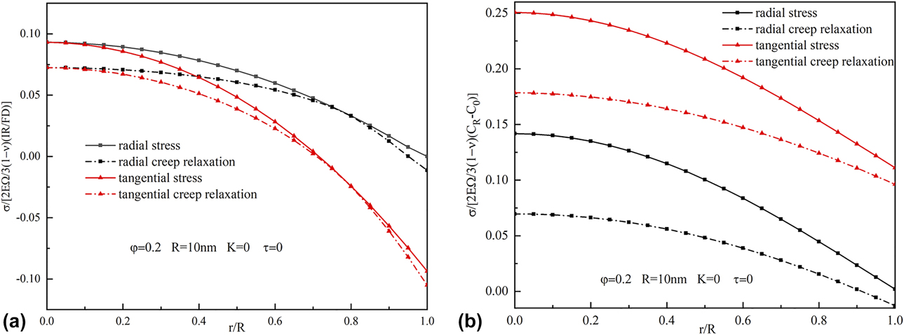
Figure 3(a) describes the radial and tangential stress evolution with creep deformation effects when the dimensionless time φ = 0.1. Figure 3(a) shows that the creep can relax the stress and the stress is obviously decreased and the creep relaxation effect is more obvious at the center of the electrode. In addition, creep deformation relaxation effectively decreases as the radius increases. It is because that DIS decreases with increase in radius, and the diffusion-induced creep also gradually decreases. DIS gradually occupies the dominant position at this time. Near the surface of the electrode, creep deformation is prone to occur because of the formation of lithiated phases. Therefore, the relaxation caused by diffusion-induced creep near the surface of the particles is more obvious. These indicate that the resulting stress should be dictated by the combination of the time scale associated with DIS and creep relaxations.
(a) The profile of stress evolution with creep relaxation in the Sn nanoparticle with a size of 10 nm at dimensionless time φ = 0.2 under galvanostatic operation. (b) The profile of stress evolution with creep relaxation in the Sn nanoparticle with a size of 10 nm at dimensionless time φ = 0.2 under potentiostatic operation.
The effect of surface stress on creep deformation
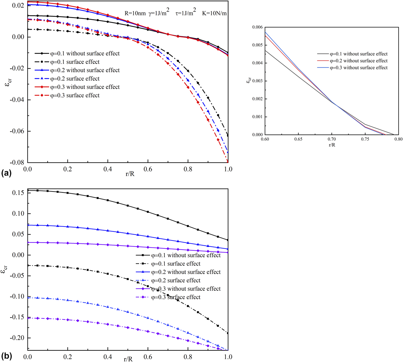
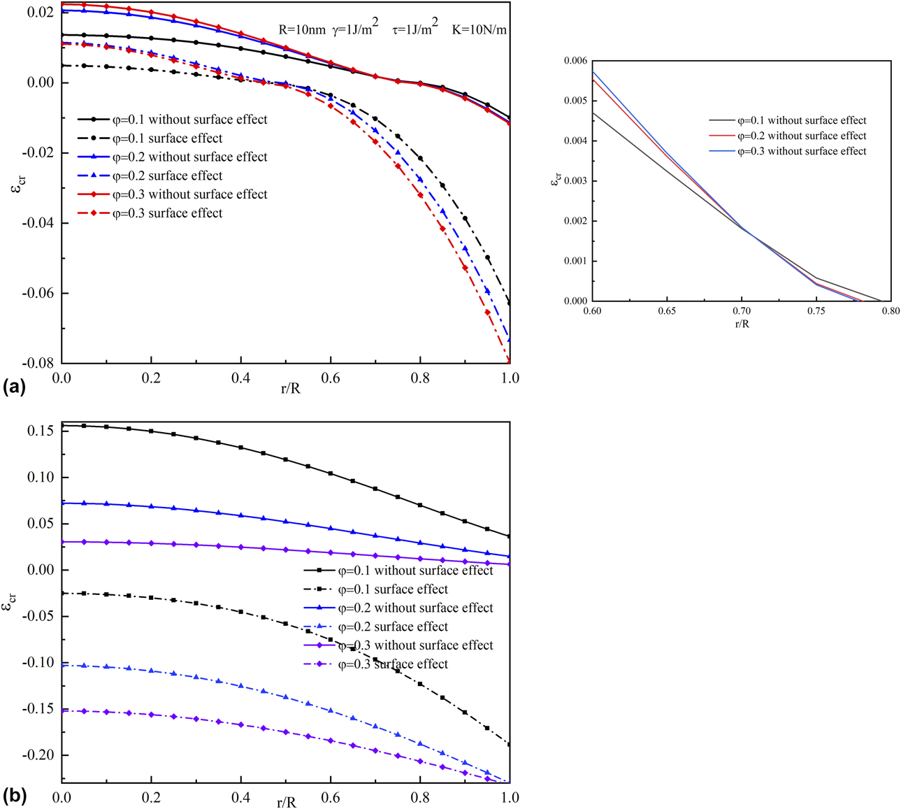
Figure 4(a) shows the profile of the creep deformation during intercalation with or without surface stress. Herein, we take a representative value of 1 J/m2 for residual surface tension τ, 10 N/m as the surface modulus values K, and 1 J/m2 for surface energy γ, all of which are as same as the value reported by Miller and coworkers. From Fig. 4(a), it can be obviously seen that the surface stress has a certain relaxation effect on creep deformation. As the position increases, the weakening effect of surface stress on creep deformation decreases. The minimum value of creep deformation is observed on the particle surface. When the electrode size is in the nanometer scale, the surface stress weakens the DIS and inhibits the diffusion-induced creep during lithiation. And it can be obtained that the surface stress has a remarkable harmful effect on the creep deformation with the increase in time. Therefore, when considering the relaxation effect of creep, the surface stress and electrode size should be taken into account.
(a) Effect of surface stress on creep deformation during intercalation for nano-spherical of 10 nm under galvanostatic operation. The smaller figure on the right is a partial enlargement of (a). (b) Effect of surface stress on creep deformation during intercalation for nano-spherical of 10nm under potentiostatic operation.
The effect of electrode size for creep deformation
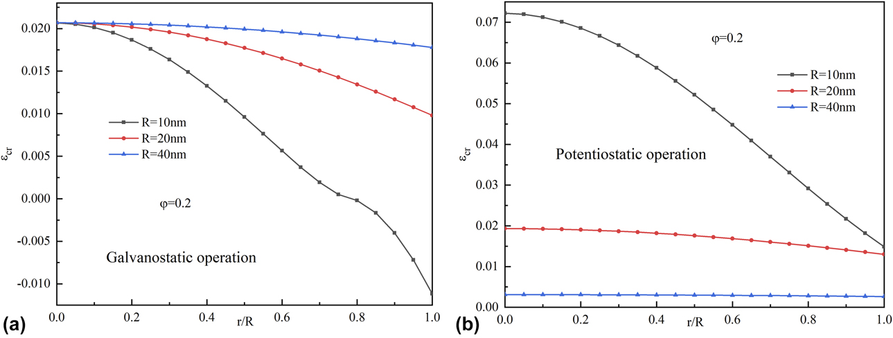
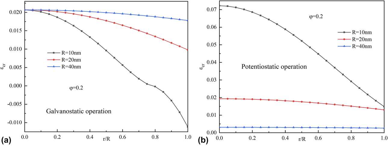
Figure 5(a) illustrates profiles of creep deformation for different electrode sizes during charging under galvanostatic operation. We can see that creep deformation increases as the electrode size increases under the same surface parameters. When the electrode size increases, the effect of size for creep deformation gradually decreases. It is because that the particle size increases to a certain value, which can reduce the effect of the surface mechanism significantly and increase the creep deformation. From Fig. 5(a), we can see that the creep deformation transforms from tensile to compression with increasing particle position. When the electrode size is smaller, the compression creep reaches the maximum at the surface. This is because the small-sized electrode has a large surface stress, resulting in the diffusion stress to become compressed and the creep deformation to become compressed.
(a) Effect of various nanoparticle sizes on creep deformation during intercalation at a dimensionless time of 0.2 under galvanostatic operation. (b) Effect of various nanoparticle sizes on creep deformation during intercalation at a dimensionless time of 0.2 under potentiostatic operation.
The effect of creep deformation for lithiation-induced fracture
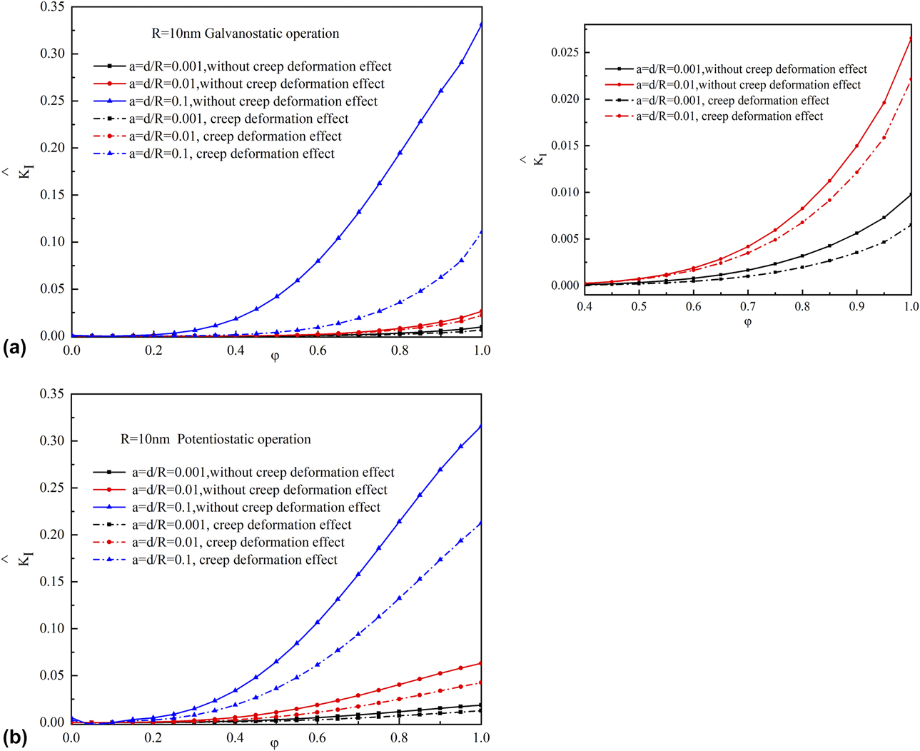
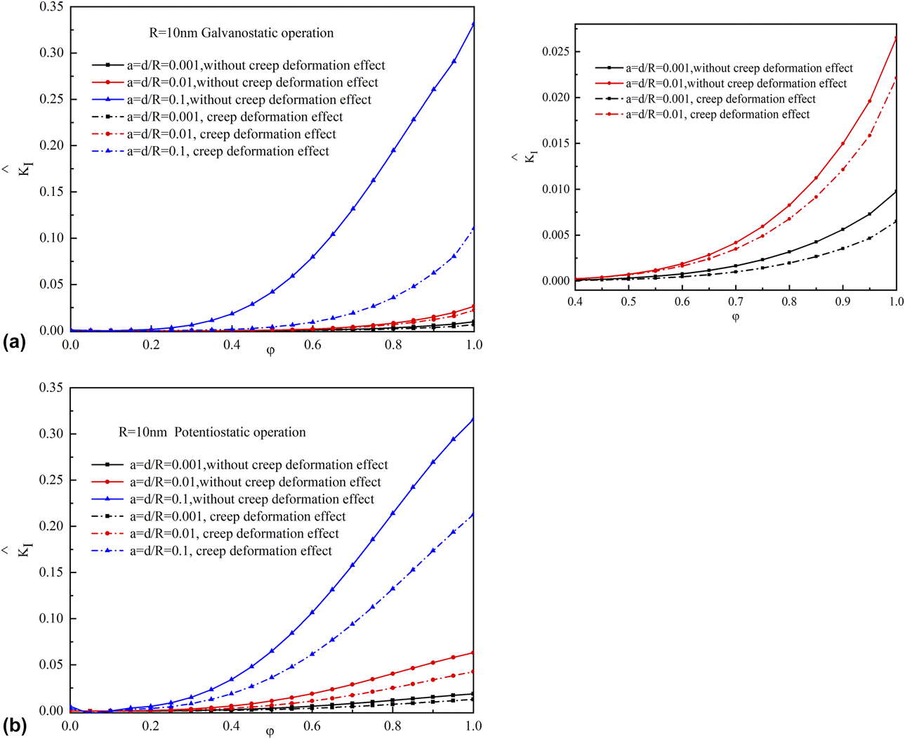
In the aforementioned calculations, the SIF evolution considering the creep deformation effect for the crack during galvanostatic operation is shown in Fig. 6(a). As shown in Fig. 6(a), SIF is increasing monotonically with charging time and SIF increases as the length of the pre-crack increases. And as the length of the pre-crack decreases, the relaxation effect of creep deformation on the fracture gradually decreases. It is because that the diffusion stress dominates the resulting stress at this time. In addition, it can be obviously seen that creep deformation suppresses the growth of SIF. Therefore, diffusion-induced creep can effectively suppress edge fracture of the electrode. Therefore, the influence of creep deformation on the critical electrode size is important, and it can make the critical electrode size larger, which can affect the safe operating region of the electrode.
(a) Variation of SIF with the charging time at different surface crack length and the presence of creep deformation under galvanostatic operation. The small figure on the right is a partial enlargement of (a). (b) Variation of SIF with the charging time at different surface crack length and the presence of creep deformation under potentiostatic operation.
The effect of creep deformation for electrode critical size
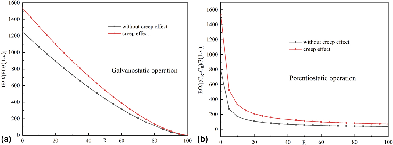
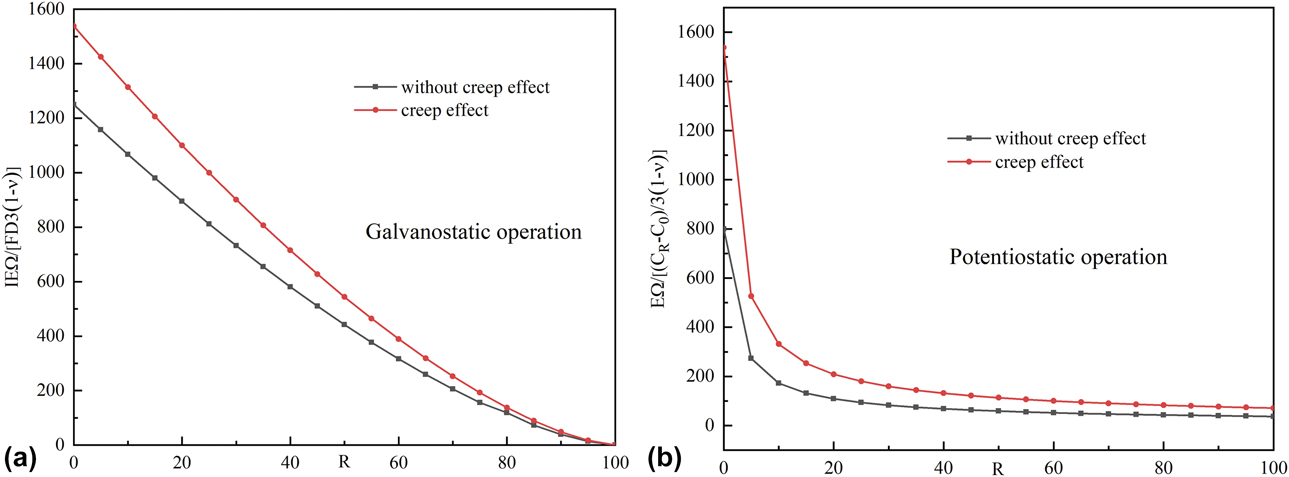
Figure 7(a) illustrates profiles of creep deformation for the electrode critical size under galvanostatic operation. It can be used to predict maximum allowed galvanostatic density for a crack growth-free operation if the electrode particle initial flaw size is known from the microstructure analysis. From Fig. 7(a), we can see that the safe area of the electrode which is the presence of the creep deformation is larger than the electrode, which is not the presence of the creep deformation; and the critical dimension of the electrode has also increased.
(a) Electrode criterion size diagrams for whether with creep the deformation effect under galvanostatic operation. (b) Electrode criterion size diagrams for whether with creep deformation effect under potentiostatic operation.
Potentiostatic operation
Diffusion concentration
As shown in Fig. 2(b), Li ions are gradually transferred from the surface of the active material to the center driven by the concentration gradient under potentiostatic operation.
It can be seen from Fig. 2(b) that the solute concentration increases with the increasing time at the same position and the solute concentration also increases continuously from the center to the surface of the sphere particle electrode. For dimensionless time φ = 0.03, at a near surface position, the curve appears to be a sharp rise and the concentration reaches a maximum value of C R at the surface position.
Stress distribution
Figure 3(b) describes the radial and tangential stress evolution with creep deformation effects when the dimensionless time φ = 0.1 under pontentiostatic operation. Figure 3(b) shows that the creep can relax the stress, and the stress is obviously decreased, and the creep relaxation effect is more obvious at the center of the electrode. Besides, the relaxation effect of creep is gradually decreasing as the position increases. As the result, the effect of surface stress on the surface near the electrode surface is obvious. In addition, creep deformation relaxation significantly decreases as the radius increases. It is because that DIS decreases with increasing radius and the diffusion-induced creep also gradually decreases. DIS gradually occupies the dominant position at this time. Therefore, when calculating the resulting stress of the electrode during the cycle, the creep stress should be considered.
The effect of surface stress on creep deformation
Figure 4(b) has shown the profile of the creep deformation during intercalation with or without the surface effect. From Fig. 4(b), it can be obviously seen that surface stress has a certain relaxation effect on creep deformation. As the position increases, the weakening effect of surface stress on creep deformation decreases. The minimum value is shown on the particle surface. And as the dimensionless time increases, the weakening effect of surface stress on creep increases. Hence, when the electrode size is in the nanometer scale, the surface stress weakens the DIS and inhibits the diffusion-induced creep during lithiation. Therefore, when considering the relaxation effect of creep, the surface stress and electrode size should be taken into account.
The effect of electrode size for creep deformation
Figure 5(b) illustrates profiles of creep deformation for different electrode sizes during charging under potentiostatic operation. We can see that creep deformation decreases as the electrode size increases under the same surface parameters and dimensionless time. It can be seen that as the electrode size increases, the effect of the electrode size on creep deformation gradually decreases. And it is because the increase in the electrode size leads to the decrease in the surface stress so that the effect of the size on creep is weakened. From Fig. 5(b), we can see that with increasing particle position, the effect of the electrode size on creep deformation is more significant. This is because the small-sized electrode has a large surface effect under surface position.
The effect of creep deformation for lithiation-induced fracture
In the previous calculations, the SIF evolution with the creep deformation effect for the crack during potentiostatic operation is shown in Fig. 6(b). As shown in Fig. 6(b), SIF is increasing monotonically with charging time and the length of the pre-crack. And the creep deformation can reduce SIF and improve the fracture resistance of the electrode. The presence of creep deformation can increase the critical fracture size of the electrode.
The effect of creep deformation for electrode critical size
Figure 7(b) illustrates profiles of creep deformation for the electrode critical size under potentiostatic operation. From Fig. 7(b), we can see that with the presence of the creep deformation of the electrode, the critical dimension of the electrode has increased. From the results, we can see that the presence of creep deformation results in a significant increase in the critical size of the electrode. It is an important guide for us to design the electrode.
Taking the representative value of K IC = 0.65 Mpa m1/2, Z = 2, and σY = 150 Mpa, the critical value of the electrode without creep deformation is  $r_{\rm{R}}^{{\rm{cr}}} = 368\;{\rm{nm}}$. However, creep deformation is
 $r_{\rm{R}}^{{\rm{cr}}} = 518\;{\rm{nm}}$, which agrees well with the reported value in in situ TEM experiment.
Based on our results, the important effect of creep deformation on electrode materials is obtained, and it is valuable for designing high-performance anodes for lithium-ion batteries.
Based on the previous results, for potentiostatic control, the stress relaxation with the creep deformation effect is more obvious; the effect of surface mechanism on creep deformation is more obvious. And the creep deformation decreases as the electrode size increases. It is because of the creep deformation generated by coupling stress. The effect of creep deformation on SIF is more obvious at small pre-creak.
For galvanostatic control, the solute insertion concentration is lower than the potentiostatic control. The creep deformation increase as the electrode size increases. It is because the coupling stress increases when the electrode size increases. The effect of creep deformation on SIF is more obvious at large pre-creak. And the safe area of the electrode is significantly larger. This is because the creep deformation effect plays a more significant role with the increased electrode size under galvanostatic operation.
The stresses evolution with creep deformation attained under potentiostatic and galvanostatic conditions are compared and contrasted. This analysis provides a charging strategy for electrodes with fracture-resistant ability.
Conclusions
In this work, the theoretical model has been used to provide insight into DIS, and the effect of stress relaxations arising from creep in the Sn nanoparticle during lithiation was established. As lithiation progressed, the tensile hoop and radial stresses were shown to advance at the center of the Sn particle because of inhomogeneous Li concentration gradients. The effects of surface stress, electrode size on creep deformation under galvanostatic, and potentiostatic operation were analyzed as a function of radius. These results revealed that surface stress is adverse to produce creep deformation. In addition, we established an electrode fracture model to study the fracture mechanism with the effect of creep deformation under galvanostatic operation and potentiostatic operation. Finally, a criterion, which is the electrode with the presence of creep deformation not to fracture, is presented, and the critical size of the Sn electrode will increase significantly compared with Si. Therefore, the results of this study suggest that Sn is a mechanically robust and highly stable material during lithiation because of creep deformation. And there is a certain competition between surface stress and creep stress. Therefore, the size of the electrode should not be too small, and the softer electrode material can be used to release stress. Hence, it provides strategies to relieve stress and design guidelines for developing Sn-based anodes with high performance. To date no research on the plastic coupling model of creep deformation is in work, and further research is needed.
Supplementary material
To view supplementary material for this article, please visit https://doi.org/10.1557/jmr.2019.346.
Acknowledgments
This work was supported by National Natural Science Foundation of China (11902144), The Natural Science Foundation of the Jiangsu Higher Education Institutions of China (19KJB430022), and the Project of Youth Talent of Guizhou Province [KY(2018)043], as well as the Ph.D. programs Foundation of Ministry of Education of China (20133221110008).