Introduction
Lithium-ion batteries are the dominant storage medium for powering portable electronics and are now finding application in electric vehicles and stationary energy storage systems. The presently used carbon anode, with a capacity of just 0.34 Ah/g and 0.8 Ah/cc, is a serious limitation to increasing the volumetric energy density of such batteries.[Reference Whittingham1] For comparison, the limits are 3.88 Ah/g and 2.1 Ah/cc for pure lithium. Silicon can react with over 4 Li/Si leading to substantially higher capacities than for carbon, 2.0 Ah/g (g total of Si + Li) and 2.4 Ah/cc, but the volume expands by over 300%. This continuing expansion and subsequent contraction on cycling leads to decrepitation of the anode composite and excessive solid electrolyte interface (SEI) formation; the latter leads to an exponentially increasing cell resistance. Nanostructuring the silicon has been reported to improve the performance,[Reference Kasavajjula, Wang and Appleby2–Reference Yao, McDowell, Ryu, Wu, Liu, Hu, Nix and Cui7] but there is still no commercial battery using a silicon-based anode.
Recently, we reported that the electrochemical performance of aluminum was much improved by using the Si–Al eutectic rather than pure aluminum.[Reference Zhou, Upreti and Whittingham3] This eutectic contains 87.4 wt.% Al and 12.6 wt.% Si.[Reference Murray and McAlister8] We found that ~2 at.% of Si was dissolved in the Al in this nanosized material. Here, we report the behavior of the silicon component of this eutectic, to determine its effectiveness as a battery anode. In the process, we identified a three-dimensional spherical microstructure of Si inside the eutectic Al–Si phase, and some solubility of Al in Si.
Experimental
The nanostructured Si spheres were obtained by etching the eutectic Al–Si powder (−325 mesh, 99%, Al:Si = 88:12 wt.%, Alfa Aesar, Ward Hill, MA) in an excess of a 3 M aqueous solution of HCl for ~6 h. The materials were characterized by x-ray diffraction and electron microscopy, and their surface area and pore size distribution determined by BET analysis. The electrochemical behavior of these porous Si materials was evaluated by constant current lithium insertion and removal. Full details are given in the Supplementary materials.
Results and discussion
The x-ray diffraction of unreacted Al–Si eutectic shows the presence of two phases, very similar to Al and Si, as indicated in Fig. 1(a). After immersion of the Al–Si eutectic in aqueous HCl acid for 6 h the Al peaks are completely removed leaving only the Si phase. Reaction overnight with vigorous stirring did not change the structure as shown in Fig. 1(c), but did break up the Si particles. The average crystallite size of the Si in both the initial Al–Si powder and the etched samples are all around 20 nm, as determined using the Scherrer equation, showing no change in crystallite size during aluminum removal. The lattice parameter of the Si phase is a = 5.454(3) Å, slightly larger than that of pure silicon, 5.431 Å. Considering the different molar volumes of Si and Al, this would suggest around 2–3 at.% Al in Si. This is very similar to the 3% Si found in the major Al phase that we reported earlier,[Reference Kasavajjula, Wang and Appleby2] and again may suggest that nano-sized material can have a different solubility for other species than bulk material, which shows no measurable mutual solubility for Si in Al or Al in Si.
XRD patterns of initial Al–Si (a), Si spheres, (b) and broken Si spheres (c), compared with the JCPDS files.

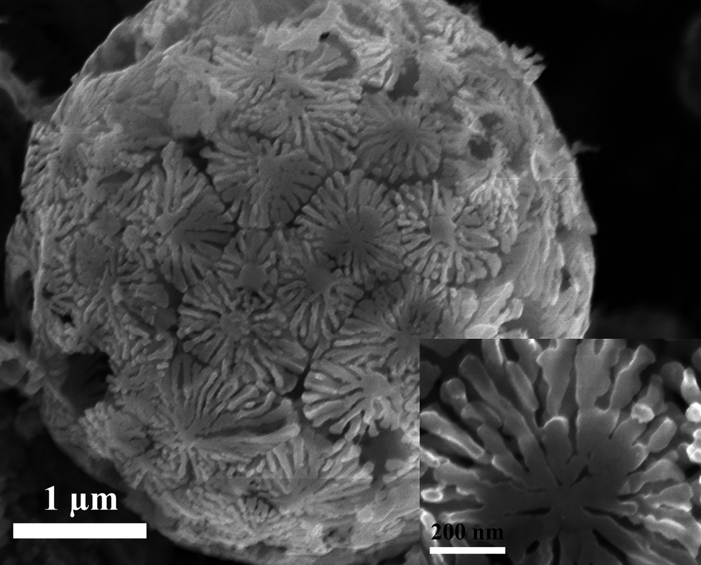
The morphology of the initial and etched materials was determined by electron microscopy. The initial Al—Si spheres have a range of particle sizes (1–10 µm), and after etching the size of the spheres is unchanged (see Supplementary materials). Figure 2 shows the morphology of the sphere where sunflower-like Si dendrites with a stem diameter under 50 nm are packed side by side to form the outer layer. The morphology of Si appears to indicate that during solidification of the Al–Si eutectic, the Si dendrites grow before Al solidification and stop when they impinge on each other. After etching the almost complete absence of aluminum (~88 wt.% or 86 vol.% in the original Al–Si) leaves a very porous structure inside the etched Si spheres. These porous Si spheres have a specific surface area of 103 m2/g with a pore size distribution varying from several nanometers to more than 50 nm, determined from the results of N2 adsorption/desorption measurements described in the Supplementary materials.
Dendritic flower-like morphology in the silicon spheres.
Energy-dispersive x-ray spectroscopy mapping found that there is still around 5 wt.% Al evenly distributed in the material (Fig. S2 in the Supplementary materials). As noted above some of this is dissolved in the silicon phase. This is not changed by overnight etching with vigorous stirring, further supporting its dissolution in the Si phase. Although the presence of some of the aluminum as an oxide layer on the surface cannot be ruled out, we believe most of the aluminum is in the silicon phase.
The electrochemical behavior of these porous Si materials was evaluated by constant current lithium insertion and removal. Over 3 Ah/g of lithium were inserted per gram of the silicon spheres on the first reaction, as indicated in Fig. 3. However, only 1.3 Ah/g of this lithium could be removed. In contrast, for the broken Si material, the first discharge capacity is a little lower (2.8 Ah/g), but much more lithium, 2.1 Ah/g, could be extracted. This capacity dropped to around 1.5 Ah/g after three cycles. However, after a further 60 cycles, the capacity still exceeded 1.15 Ah/g, showing a very low capacity decay (0.006 Ah/g) per cycle. These superior values for the broken spheres are almost certainly due to better access of the electrolyte and/or the carbon conductor to the reacting silicon. These values are more than double those for the conventional graphite anode (0.37 Ah/g). The coulombic efficiency of broken Si was 76.5% in the first cycle and increased to a steady 99% after a few cycles as indicated in Fig. 3.
Electrochemical cycling of the Si spheres before (s-Si) and after breaking (b-Si) at 0.5 mA/cm2 (ca. 200 mA/g) between 0.01 and 1.5 V. The first cycle current density was 0.3 mA/cm2. The electrodes were made of Si, carbon black additive and binder in a weight ratio of 70:20:10. Capacities were calculated based on the weight of Si (2–3 mg/cm2).
This silicon morphology should be conducive to high rates of reaction with lithium, and the data in Fig. 4 bear this out. The capacity at 8 mA/cm2 is more than 85% of that at 0.5 mA/cm2 and as important as most of this capacity on lithium removal (that obtained when this material is used as the anode in a lithium-ion battery) can be obtained below 0.75 V. Further research is needed on this and most other anode materials to reduce the first discharge excess capacity that is almost certainly due to the formation of SEI layers and other side reactions with, for example, the added carbon. In addition, the cycling efficiency must be improved to around 99.9% to reduce the capacity loss on extended cycling.
(Upper) Capacity as a function of the lithium removal rate for the broken Si spheres. (Lower) The voltage curves on lithium removal at 0.5, 2 and 8 mA/cm2. In all cases the lithium was inserted at 0.5 mA/cm2. The loading of Si was 2.16 mg/cm2, so that a rate of 8 mA/cm2 corresponds to 3.7 A/g.
Conclusions
The silicon component in the Si–Al eutectic was analyzed and found to contain some dissolved aluminum and to have a spherical morphology containing a dendritic flower-like structure. This spherical structure was found to be active as an anode material in lithium batteries, and that breaking up the spheres enhanced the capacity retention on cycling the lithium in and out of the structure.
Acknowledgments
This work was supported by the Assistant Secretary for Energy Efficiency and Renewable Energy, Office of Vehicle Technologies of the US Department of Energy under contract no. DE-AC02-05CH11231, under the Batteries for Advanced Transportation Technologies (BATT) Program subcontract no. 6807148.
Supplementary materials
For supplementary materials for this article, please visit http://dx.doi.org/10.1557/mrc.2013.20