
1. Introduction
For an isolated, stationary cylinder of diameter  $d$ placed in a uniform flow of velocity
 $U$, the wake transitions from a steady two-dimensional state to unsteady periodic shedding of vortices at a Reynolds number
 $Re=Ud/\nu \approx 46$ (Roshko Reference Roshko1954; Taneda Reference Taneda1956; Provansal, Mathis & Boyer Reference Provansal, Mathis and Boyer1987; Henderson Reference Henderson1997,
 $\nu$ is the kinematic viscosity). As the Reynolds number is increased, three-dimensional instabilities appear, in particular mode
 $A$ at
 $Re\approx 190$ (Williamson Reference Williamson1988, Reference Williamson1996; Henderson Reference Henderson1997) and mode
 $B$ at
 $Re\approx 260$ (Williamson Reference Williamson1996; Henderson Reference Henderson1997).
Elastically mounted cylinders experience vortex-induced vibration (VIV) when the wake is unsteady. Early experimental studies conducted by Feng (Reference Feng1968), Sarpkaya (Reference Sarpkaya1979) and Williamson & Roshko (Reference Williamson and Roshko1988), complemented more recently by work and reviews from Khalak & Williamson (Reference Khalak and Williamson1996, Reference Khalak and Williamson1999), Govardhan & Williamson (Reference Govardhan and Williamson2000) and Williamson & Govardhan (Reference Williamson and Govardhan2004), offer a comprehensive overview on the subject for Reynolds numbers  $Re>1250$, where the wake is three-dimensional. Concerning the different regimes of synchronous response, it was shown that a cylinder with low mass damping exhibits an ‘initial’, an ‘upper’ and a ‘lower’ amplitude branch, whereas in the case of high mass damping, the upper branch is non-existent. The vortex wake exhibits a ‘2S’ mode in the initial branch, i.e. two single vortices are shed in each cycle, and a ‘2P’ mode in the lower and upper branches, i.e. two pairs of vortices are shed in each cycle (Williamson & Roshko Reference Williamson and Roshko1988). The first transition from the initial to the upper branch is associated with a jump in the vortex phase (defined as the phase between vortex force and displacement) and a response frequency that approaches the natural frequency of the cylinder system in the fluid medium. A distinct switch in the timing of vortex shedding is also observed as the vortex wake mode changes from 2S to 2P, causing the amplitude of cylinder oscillations to increase and reach a peak of about one cylinder diameter. The second transition, from upper to lower branch, is correlated with a jump in the total phase (defined as the phase between total force and displacement), a response frequency that passes through the natural frequency of the cylinder system in vacuum (thus a slight increase in the response frequency occurs) and a decrease in oscillation amplitude. Unlike the first transition, it is not associated with a switch in timing of the shedding (Williamson & Govardhan Reference Williamson and Govardhan2004).
In the low- $Re$ regime, where the vortex street is fully two-dimensional, one set of experiments was performed by Anagnostopoulos & Bearman (Reference Anagnostopoulos and Bearman1992) at
 $Re=90\text {--}150$. Amongst the numerical investigations undertaken are those by Blackburn & Karniadakis (Reference Blackburn, Karniadakis, Chung, Natvig, Das and Li1993), Blackburn & Henderson (Reference Blackburn and Henderson1996), Shiels, Leonard & Roshko (Reference Shiels, Leonard and Roshko2001), Guilmineau & Queutey (Reference Guilmineau and Queutey2002), Leontini, Thompson & Hourigan (Reference Leontini, Thompson and Hourigan2006), Prasanth & Mittal (Reference Prasanth and Mittal2008, Reference Prasanth and Mittal2009) and Mysa, Kaboudian & Jaiman (Reference Mysa, Kaboudian and Jaiman2016). From the latest studies, it is understood that the branching behaviour of the cylinder VIV response starts to develop in the low-
 $Re$ regime and is therefore not a product of the three-dimensionality of the flow.
Previous studies by Taneda (Reference Taneda1965) showed that the presence of a stationary wall near a cylinder stabilises the wake, delaying the onset of vortex shedding to  $Re\approx 100$ when the distance
 $G$ to the wall is less than a critical value around
 $G/d=0.2\text{--}0.3$ (Lei, Cheng & Kavanagh Reference Lei, Cheng and Kavanagh1999). When the wake is unsteady, the strength of the vortex shedding decreases with decreasing gap ratio. Taneda (Reference Taneda1965) observed a single row of vortices at
 $G/d=0.1$, whereas alternate vortex shedding developed at
 $G/d=0.6$ (Taneda Reference Taneda1965; Zdravkovich Reference Zdravkovich and Yang1985). At small gap ratios (
 $G/d\le 0.1$), the vortices are generated by the interaction between the separating shear layer from the top of the cylinder and the secondary vortex shedding from the wall boundary layer (Stewart et al. Reference Stewart, Thompson, Leweke and Hourigan2010b; Rao et al. Reference Rao, Stewart, Thompson, Leweke and Hourigan2011, Reference Rao, Thompson, Leweke and Hourigan2013c). For
 $G/d\lesssim 0.3$, three-dimensionality appears before the onset of vortex shedding, similar to what occurs in the flow over a backward-facing step (Armaly et al. Reference Armaly, Durst, Pereira and Schönung1983).
Where near-wall VIV is possible, the dynamics of the coupled system is complex. Numerous studies have looked into the effect of the wall on a vibrating cylinder with one or two degrees of freedom (DOF) for its motion, namely in the transverse and streamwise directions, for moderate to high Reynolds numbers. Experiments conducted by Fredsøe et al. (Reference Fredsøe, Sumer, Andersen and Hansen1987) and Raghavan, Bernitsas & Maroulis (Reference Raghavan, Bernitsas and Maroulis2009) showed that, unlike for the stationary cylinder case, vortex shedding may occur even at very small gap ratios. This was confirmed numerically by Zhao & Cheng (Reference Zhao and Cheng2011) and Wang, Hao & Tan (Reference Wang, Hao and Tan2013). Tsahalis (Reference Tsahalis1983) reported that the trajectory of the cylinder has an oval shape. Yang, Gao & Wu (Reference Yang, Gao, Wu, Chung, Hong, Prinsenberg and Nagata2008) measured that, in the turbulent regime, the vibration amplitudes of a cylinder allowing 2-DOF motion near a wall increase for larger gap ratios. For small mass ratios, Yang et al. (Reference Yang, Gao, Jeng and Wu2009) showed that the vibration range is larger and that the dimensionless vibration frequency is higher than for larger mass ratios. Zhao & Cheng (Reference Zhao and Cheng2011) studied numerically the VIV of a cylinder close to a plane wall where bounceback was also considered; they identified three vortex shedding modes, which depend on the reduced velocity  $U/(\,f_{n}d)$, where
 $f_{n}$ is the natural frequency of the system in a quiescent fluid. Experiments of a transversely vibrating neutrally buoyant cylinder at various heights above a plane wall (
 $G/d=0.05\text {--}2.5$) were conducted by Wang et al. (Reference Wang, Hao and Tan2013) for
 $Re=3000\text {--}13\,000$, showing that VIV exists at all gap ratios considered and that the presence of the wall causes nonlinearities in the cylinder response. For small gaps, the wake pattern is characterised by a single row of vortices formed in the upper shear layer and shed periodically, whereas for high gap ratios a double-rowed vortex street is found. At
 $Re=100$, a numerical investigation by Tham et al. (Reference Tham, Gurugubelli, Li and Jaiman2015) found that a third response branch exists between the initial and lower-type branches for
 $G/d\le 0.60$, and that for
 $G/d\geq 5$ the system becomes equivalent to that of the isolated cylinder. Two- and three-dimensional simulations at
 $Re=200$ and 1000 and
 $G/d=0.9$ carried out by Li et al. (Reference Li, Yao, Yang, Jaiman and Khoo2016) showed that the wall proximity generates a mean lift force and enhances the streamwise oscillations while reducing their frequency in comparison with the isolated configuration.
When a rotation is imposed on the cylinder, a different flow dynamics is observed. In an unbounded flow, the wake becomes asymmetrical (Tang & Ingham Reference Tang and Ingham1991) and the elimination of one or both recirculation regions in the wake can occur, depending on the Reynolds number and the rotation rate. The transition to unsteady flow is also affected – it is in most cases delayed or suppressed – and a multitude of different three-dimensional modes exist (Mittal & Kumar Reference Mittal and Kumar2003; Radi et al. Reference Radi, Thompson, Rao, Hourigan and Sheridan2013; Rao et al. Reference Rao, Leontini, Thompson and Hourigan2013a,Reference Rao, Leontini, Thompson and Houriganb). Stewart et al. (Reference Stewart, Thompson, Leweke and Hourigan2010b) and Rao et al. (Reference Rao, Stewart, Thompson, Leweke and Hourigan2011) studied cylinders rotating and translating near a wall at various imposed rotation rates and found that prograde motion destabilises the flow, whereas retrograde rolling delays the onset of the instability.
Using two- and three-dimensional simulations, Bourguet & Lo Jacono (Reference Bourguet and Lo Jacono2014) investigated flow-induced vibrations of a circular cylinder free to oscillate in the transverse direction and subjected to a forced rotation about its axis at  $Re=100$ and for a large range of reduced velocities and rotation rates. They identified two novel wake patterns, named ‘
 $\textrm {T}+\textrm {S}$’ and ‘U’, associated with the largest vibration amplitudes and the low-frequency vibration regime, respectively. The
 $\textrm {T}+\textrm {S}$ pattern is characterised by a triplet of vortices and a single vortex shed per cycle, and the U pattern by a transverse undulation of the spanwise vorticity layers without vortex formation, indicating that flow-induced vibrations may also occur in the absence of vortex shedding. Overall, the time-averaged displacement and lift coefficient tend to increase with the rotation rate. Zhao, Cheng & Lu (Reference Zhao, Cheng and Lu2014) studied numerically the VIV of a 1- and 2-DOF rotating cylinder at
 $Re=150$ and low mass ratio. They found that the rotation of the cylinder increases the response amplitude for the 1-DOF motion in the transverse direction. In the 2-DOF case, the streamwise response amplitude increases significantly with increasing rotation rate, first exhibiting one initial branch and then two such branches at higher values. In both 1- and 2-DOF configurations, hysteresis regions were detected in the amplitude response.
Wong et al. (Reference Wong, Zhao, Lo Jacono, Thompson and Sheridan2017) carried out experiments on VIV of a cylinder of low mass ratio free to oscillate in the transverse direction with imposed rotation around its axis. Their study showed that forced rotation can cause peak response amplitudes of up to 1.4 diameters in the range of reduced velocities associated with the upper amplitude response branch of a non-rotating cylinder. For higher rotation rates and for reduced velocities outside the synchronisation range, a new chaotic wake mode ‘C(AS)’ was observed, characterised by the shedding of small asymmetric vortices as the wake switches between a wider and a narrower state.
Most previous studies consider cylinders placed in a free stream without wall interactions or rotation. In cases where the presence of a wall and the rotation of the body were taken into account, the velocities and rotation rates were for the most part set to be constant. A cylindrical bluff body moving freely near a surface has none of its velocity, rotation or trajectory imposed externally, these are instead determined by the drag, lift and torque from the motion through the surrounding fluid, as well as by gravity driving this motion and the contact force at the wall. The resulting body and flow dynamics in such a configuration, i.e. the translation, rotation, wake structure and flow-induced vibrations, is largely unknown. The case of a spherical bluff body rolling freely down an incline has received some attention in the literature; a number of experimental (e.g. Carty Reference Carty1957; Jan & Chen Reference Jan and Chen1997), analytical (e.g. Chhabra & Ferreira Reference Chhabra and Ferreira1999) and numerical (e.g. Zhang et al. Reference Zhang, Soga, Kumar, Sun and Jin2017) studies have focussed mainly on the drag coefficient and the motion history of the rolling sphere.
This paper investigates numerically the free motion of cylinders rolling without slipping on an inclined wall under the effect of gravity, buoyancy and fluid forces, in the idealised configuration of two-dimensional flow. This situation introduces new parameters: the gravitational acceleration, the inclination angle of the wall and the ratio of cylinder and fluid densities. It also changes the nature of the problem, which now involves a coupled interaction between the fluid forces and the cylinder motion. When vortex shedding occurs, these forces are unsteady, and the translational (and rotational) velocity of the cylinder is not constant, leading to streamwise vortex-induced vibrations. The aim here is to characterise the flow behaviour as a function of the governing parameters and to investigate the flow transitions, the saturated flow states and the fluid–structure interactions.
The problem definition, equations of motion and numerical formulation are given in § 2. Section 3 then provides a quantitative assessment of the effect of the small gap between the cylinder and the wall, which is necessary to guarantee numerical stability and which is known to lead to singularities in the force coefficients when its size decreases to zero. The transition to unsteady flow is treated in § 4. The properties of the asymptotic rolling motion and vortex-induced vibrations are presented in § 5 and compared to the constant-velocity case. Finally, § 6 shows results concerning the initial transient when the motion starts from rest. Section 7 contains the conclusions.
2. Problem definition
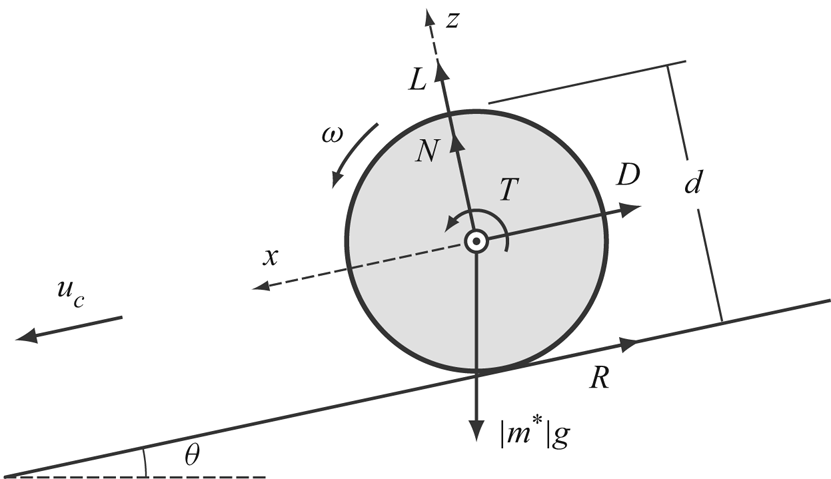
We investigate the fluid–structure interaction problem of a circular cylinder rolling freely down a surface of constant slope under gravity through a viscous incompressible fluid. A natural reference case for comparison is that of a circular cylinder rolling along a surface at a constant specified velocity. The configuration, including relevant notation, is shown in figure 1.
Schematic of a cylinder rolling along an inclined plane of slope angle  $\theta$. Its translational and angular velocities are
 $u_c$ and
 $\omega$, respectively. The frame of reference
 $(x,z)$ is attached to the centre of the body, and the different forces exerted on it are illustrated: the fluid forces (drag
 $D$, lift
 $L$ and torque
 $T$), the mechanical forces (reactions of the wall on the body,
 $N$ and
 $R$) and gravity/buoyancy (
 $|m^*|g$).

The uniform-rolling case has been studied previously by Taneda (Reference Taneda1965), Stewart et al. (Reference Stewart, Thompson, Leweke and Hourigan2010a,Reference Stewart, Thompson, Leweke and Houriganb) and Houdroge et al. (Reference Houdroge, Leweke, Hourigan and Thompson2017), providing a comprehensive set of results for this configuration. In this paper, a few simulations with uniform rolling are repeated, in order to enable high-fidelity comparisons with the new predictions for the current problem. The corresponding force histories and flow dynamics provide a benchmark for comparison of the asymptotic state, allowing an assessment of the differential effects induced by the free movement of the cylinder.
In both configurations, the simulations are performed in a frame of reference placed at the centre of the cylinder. For the constant-velocity case, this is equivalent to the fluid and wall moving past a rotating cylinder with a fixed centre of mass. In the free-rolling case, the frame of reference is not an inertial frame.
2.1. Governing equations
The governing equations are the continuity and incompressible Navier–Stokes equations for the motion of the fluid, along with the linear and angular momentum balance for the motion of the cylinder.
2.1.1. Fluid equations
Let  $\boldsymbol {u}(x, z, t)$ represent the time-dependent two-dimensional velocity of the fluid. For an incompressible flow, the continuity equation is
 \begin{equation} \boldsymbol{\nabla}\boldsymbol{\cdot}\boldsymbol{u}=0,\end{equation}
and the general form of the Navier–Stokes equation in an accelerating frame is
 \begin{equation} \frac{\partial\boldsymbol{u}}{\partial t} + \boldsymbol{u}\boldsymbol{\cdot}\boldsymbol{\nabla}\boldsymbol{u}=-\frac{1}{\rho_f}\boldsymbol{\nabla} P+\nu\nabla^2\boldsymbol{u}-\frac{\mathrm{d}\boldsymbol{u}_{\boldsymbol{c}}}{\mathrm{d}t}, \end{equation}
where  $\rho _f$ is the density of the fluid,
 $P$ the static pressure and
 $\boldsymbol {u}_{\boldsymbol {c}}=(u_c,0)$ is the velocity of the body, which is of the sense opposite to that of the frame of reference. The last term of (2.2) is obtained by applying Newton's second law of motion to the centre of mass of the body; its presence underlines the coupled nature of this problem.
2.1.2. Body acceleration equations
According to Newton's second law,
 \begin{equation} m_c\,\boldsymbol{a}_{\boldsymbol{c}} = \sum \boldsymbol{F}, \end{equation}
where  $m_c$ is the mass (per unit span) of the cylinder,
 $\boldsymbol {a}_{\boldsymbol {c}}=(\ddot {x}_c,\ddot {z}_c$) its acceleration and
 $\sum {\boldsymbol {F}}$ the sum of all forces exerted on the body. For the configuration described in figure 1, this gives
 \begin{gather} m_c\ddot{x}_c=|m^*|g\sin\theta-D-R, \end{gather}
 \begin{gather}m_c\ddot{z}_c=-|m^*|g\cos\theta+N+L, \end{gather}
where the buoyant mass,  $m^* = m_c - m_f$, is the mass of the cylinder in excess of that of the fluid it displaces (
 $m_f$). Assuming that the body stays at a fixed distance from the surface, the
 $z$-component of the acceleration is zero, which leads to the following expression for the normal component of the reaction force exerted by the wall on the body
 \begin{equation} N = |m^*|g\cos\theta-L. \end{equation}
2.1.3. Torque equation
The balance of angular momentum for the rolling cylinder is given by
 \begin{equation} I\dot{\omega}=\sum M, \end{equation}
where  $I$ is the body's moment of inertia and
 $\sum {\boldsymbol {M}}$ is the sum of all moments acting on the cylinder. For a cylinder of uniform density,
 $I = \frac {1}{2} m_c ({d}/{2})^2$. The moments are the fluid torque
 $T$ and the torque
 $(d/2)R$ applied by the contact reaction force
 $R$. With this, (2.7) becomes
 \begin{equation} \frac{1}{2} m_c ({d}/{2})^2\dot{\omega} = T +\frac{d}{2}R. \end{equation}
The no-slip boundary condition between the surface of the cylinder and the wall results in a kinematic relationship between the translational velocity of the cylinder  $\dot {x}_c$ (
 $=u_c$) and its angular velocity:
 $\dot {x}_c=(d/2){\omega }$. Therefore
 $\dot {\omega }=(2/d)\ddot {x}_c$, giving the following expression for the reaction force
 $R$, from (2.8):
 \begin{equation} R=\frac{1}{2}m_c\ddot{x}_c-\frac{2}{d}T. \end{equation}
Substituting this in (2.4) provides an expression for the cylinder acceleration
 \begin{equation} \ddot{x}_c\equiv\frac{\mathrm{d} u_c}{\mathrm{d} t}=\frac{2}{3}\left[ \left(1-\frac{1}{\beta}\right)g\sin\theta -\frac{4D}{{\rm \pi} d^2\rho_c}+ \frac{8T}{{\rm \pi} d^3\rho_c}\right], \end{equation}
where  $\beta =\rho _c/\rho _f$ is the ratio of the body density and the density of the fluid. The range of
 $\beta$ considered in this study is 0.1–200. Note that for
 $\beta <1$, the cylinder is positively buoyant, it can be considered to be rolling upwards beneath an inclined surface.
2.1.4. Non-dimensional equations
Unlike the case of a uniformly rolling cylinder, where the imposed translational velocity provides a scale for non-dimensionalisation, the cylinder velocity is here a function of the other problem parameters (and also of time, depending on the regime). However, a new velocity scale  $V$ can be obtained by considering the asymptotic flow state, where a balance exists between the fluid forces (per unit mass), which are proportional to
 $V^2$, and gravitational/buoyancy forces, given by
 $|m^*|g\sin \theta$. This leads to the following expression for the velocity scale:
 \begin{equation} V = \sqrt{\frac{d}{2}|\beta-1|g\sin\theta}, \end{equation}
where the length scale needed for dimensional compatibility was chosen as the cylinder radius, a choice justified a posteriori by the fact that the observed asymptotic velocities are indeed close to  $V$.
Scaling the lengths by the diameter  $d$, velocities by
 $V$, time by
 $d/V$ and pressure by
 $\rho _f V^2$ allows the governing equations to be written in terms of non-dimensional variables (denoted by asterisks) as
 \begin{gather} \nabla^*\boldsymbol{\cdot} \boldsymbol{u}^{*}=0, \end{gather}
 \begin{gather}\frac{\partial\boldsymbol{u}^{*}}{\partial t^*}+\boldsymbol{u}^{*} \cdot\nabla^*\boldsymbol{u}^{*}=-\nabla^*P^*+\frac{1}{Re^*}\nabla^{*2} \boldsymbol{u}^{*}-\frac{\mathrm{d} \boldsymbol{u}_{\boldsymbol{c}}^{*}}{ \mathrm{d}t^*}, \end{gather}
 \begin{gather}\frac{\mathrm{d} u_{c}^*}{\mathrm{d} t^*}=\frac{4}{3\beta}\left[1 -\frac{{u_c^*}^2}{\rm \pi} \left(C_D-C_T\right)\right], \end{gather}
where  $Re^* = Vd/\nu$ is a modified Reynolds number based on the new velocity scale (2.11). The force and torque coefficients (per unit length) are defined in the usual way:
 \begin{gather} C_D =D/\left(\tfrac{1}{2}d\rho_fu_c^2\right), \end{gather}
 \begin{gather}C_L =L/\left(\tfrac{1}{2}d\rho_fu_c^2\right), \end{gather}
 \begin{gather}C_T =T/\left(\tfrac{1}{4}d^2\rho_fu_c^2\right). \end{gather}
Equations (2.12)–(2.14) for the freely rolling cylinder indicate that this fluid–structure problem is governed by two non-dimensional parameters, in contrast to the uniformly rolling cylinder, whose state is fully defined by just the Reynolds number. Here, the modified Reynolds number  $Re^*$, which involves a combination of the gravitational acceleration (
 $g$), the slope angle (
 $\theta$) and the mass ratio (
 $\beta$), and separately the mass ratio
 $\beta$, both determine the evolution of the flow and the cylinder motion. The asymptotic cylinder velocity
 $U$ can be obtained from (2.14). For this, the cylinder acceleration should be zero, which leads to
 $u_c^*=[{\rm \pi} /(C_D-C_T)]^{1/2}=U^*$. This relation remains true for unsteady flow involving vortex shedding and flow-induced vibrations, if one considers time-mean quantities
 \begin{equation} \bar{U}^*=\left(\frac{\rm \pi}{\bar{C}_D-\bar{C}_T}\right)^{{1}/{2}}. \end{equation}
The non-dimensional asymptotic (mean) velocity is independent of  $\beta$, even if the dimensional velocity
 $U=U^*V$ (or
 $\bar {U}=\bar {U}^*V$), as well as the amplitude of the cylinder oscillation (see §§ 5 and 6) depend on this parameter.
In order to compare the results to those obtained for the constant-velocity case, it is useful to also define a Reynolds number  $\overline {Re} = \bar {U}d/\nu$, based on the asymptotic (mean) translation velocity of the cylinder.
2.2. Computational method
A description of the method used to solve the fluid flow equations (2.12) and (2.13) can be found in Thompson et al. (Reference Thompson, Hourigan, Cheung and Leweke2006), with relevant similar applications presented in a number of articles, including Thompson, Hourigan & Sheridan (Reference Thompson, Hourigan and Sheridan1996) and Thompson, Leweke & Williamson (Reference Thompson, Leweke and Williamson2001). The extension to moving bodies and fluid–structure interactions is discussed in Ryan, Thompson & Hourigan (Reference Ryan, Thompson and Hourigan2005, Reference Ryan, Thompson and Hourigan2007), Leontini, Thompson & Hourigan (Reference Leontini, Thompson and Hourigan2007), Rao et al. (Reference Rao, Stewart, Thompson, Leweke and Hourigan2011) and Lee, Hourigan & Thompson (Reference Lee, Hourigan and Thompson2013). For the sake of completeness, a brief summary of the computational approach follows.
A spectral-element technique based on the Galerkin finite-element method (see Karniadakis & Sherwin Reference Karniadakis and Sherwin1999) is employed to evaluate the spatial derivatives in the two-dimensional domain. The solution variables are approximated using high-order Lagrangian polynomial interpolants associated with Gauss–Lobatto–Legendre quadrature points within each element.
For the time integration, a high-order three-step time-splitting scheme is used. The three steps encompass the advection and cylinder-movement terms, the pressure term and the diffusion term of the Navier–Stokes equations, respectively. The nonlinear terms, i.e. the advection and cylinder acceleration terms, are treated explicitly using a third-order Adams–Bashforth method and a semi-implicit Adams–Moulton scheme in subsequent iterations (using estimates at the next time step from previous iterations). The (linear) pressure and diffusion substeps are both treated implicitly; taking the divergence of the equation for pressure and enforcing continuity at the end of the step amounts to solving a Poisson equation for the pressure, and the second-order Crank–Nicolson scheme allows for the diffusion term to be treated (see, e.g. Canuto et al. Reference Canuto, Hussaini, Quarteroni and Zang2007). In practice, these substeps are implemented by computing the lower–upper decomposition at the start of the simulation for each of these matrix problems, so that the subsequent pressure and diffusion substeps involve straightforward sparse matrix multiplications.
The two-dimensional mesh used is non-deformable and has significantly enhanced resolution in the vicinity and downstream of the cylinder. After some initial optimisation and tuning, the final mesh consisted of 1472 macro-elements, each comprising  $N=5(\times 5)$ internal collocation points. The upstream, downstream and upper boundaries are located at
 $x=25d$,
 $x=-25d$ and
 $z=50d$, respectively, resulting in a blockage ratio of 2 %. This mesh is the same as the one used in a previous study on uniformly rolling cylinders (Houdroge et al. Reference Houdroge, Leweke, Hourigan and Thompson2017), where a full resolution and validation study was undertaken.
To avoid a mesh singularity at the point of contact between the cylinder and the wall, a small gap of size  $G$ is imposed, in line with previous simulations of uniformly rolling cylinders (Stewart et al. Reference Stewart, Hourigan, Thompson and Leweke2006, Reference Stewart, Thompson, Leweke and Hourigan2010b; Rao et al. Reference Rao, Stewart, Thompson, Leweke and Hourigan2011). Earlier studies (Jeffrey & Onishi Reference Jeffrey and Onishi1981; Merlen & Frankiewicz Reference Merlen and Frankiewicz2011) have shown that, as the gap is reduced to zero, the pressure before and after the contact point becomes unbounded. Merlen & Frankiewicz (Reference Merlen and Frankiewicz2011) examined the cylinder rolling at constant speed using a combination of lubrication theory and finite-element simulation to predict the flow at finite Reynolds numbers. In the limit of zero gap size, the pressure field becomes discontinuous, with the pressure approaching positive infinity ahead of the cylinder and negative infinity behind it. In the zero-gap limit for Stokes flow, this leads to an infinite drag force, while the positive and negative pressure contributions cancel to give zero lift. This is not the case for finite Reynolds numbers, where the pressure distribution associated with the non-symmetrical upstream and downstream flow leads to a positive lift coefficient, even for very small Reynolds numbers. This was clearly shown by Merlen & Frankiewicz (Reference Merlen and Frankiewicz2011) for Reynolds numbers below
 $Re=1$. The drag prediction indicates that the cylinder should not be able to roll with a zero gap size. The resolution of this paradox has been proffered as requiring cavitation or release of absorbed gas in a liquid, as demonstrated in experiments by Seddon & Mullin (Reference Seddon and Mullin2006), or compressibility effects if the fluid is a gas. Other practical factors may also contribute, such as surface roughness (as discussed in Prokunin Reference Prokunin2003) or cylinder and wall straightness.
The influence of the gap size on the pressure and force coefficients, as well as on the added mass, are again analysed in detail in the following section, and its effect on the freely rolling cylinder configuration is also documented in § 5. For the study of the start-up transient in § 6, a constant gap size  $G/d=0.005$ was chosen as a practical compromise, balancing the requirements for accuracy of the force components, time step restrictions and code stability. As shown in § 3 below, and as observed in previous work on uniformly rolling cylinders (Stewart et al. Reference Stewart, Hourigan, Thompson and Leweke2006, Reference Stewart, Thompson, Leweke and Hourigan2010b; Rao et al. Reference Rao, Stewart, Thompson, Leweke and Hourigan2011; Houdroge et al. Reference Houdroge, Leweke, Hourigan and Thompson2017), the gap size has little effect on the formation and shedding of large vortical structures away from the gap region.
Further details on the mesh and computational method can be found in Houdroge et al. (Reference Houdroge, Leweke, Hourigan and Thompson2017).
2.3. Linear stability analysis
The transition from steady (asymptotic) flow over the rolling cylinder to vortex shedding and flow-induced vibrations was determined using linear stability analysis. Due to the coupled nature of the problem, the equations for both the fluid and the cylinder have to be solved simultaneously. The pressure  ${p}$, the flow velocity
 ${\boldsymbol {u}}$ and the cylinder velocity
 $\boldsymbol {u}_{\boldsymbol {c}}$ can be expressed as the sum of their steady base states
 ${P}$,
 ${\boldsymbol {U}}$ and
 ${\boldsymbol {U}_{\boldsymbol {c}}}$, and perturbations
 ${p'}$,
 $\boldsymbol {u}'$ and
 $\boldsymbol {u}_{\boldsymbol {c}}'$, respectively
 \begin{equation} {p} = {P} + {p'}, \quad \boldsymbol{u} = \boldsymbol{U} + \boldsymbol{u}', \quad \boldsymbol{u}_{\boldsymbol{c}} = \boldsymbol{U}_{\boldsymbol{c}} + \boldsymbol{u}_{\boldsymbol{c}}', \end{equation}
where  $\boldsymbol {U}_{\boldsymbol {c}} = (U_c,0)$. The drag and torque in the equation of motion for the cylinder (2.10) are linear in the pressure and the flow velocity (viscous forces). Therefore,
 $D({\boldsymbol {u}},p) = D({\boldsymbol {U}}+{\boldsymbol {u}'}, P + p') = D({\boldsymbol {U}},P) + D({\boldsymbol {u}'},p') \equiv \bar {D} + D'$, and similarly
 $T = \bar {T} + T'$. Thus, the perturbation drag is a function of the perturbation velocity and pressure, as is the perturbation torque.
Substituting the above relations into (2.2) and (2.10), subtracting the terms corresponding to the base flow and linearising, leads to
 \begin{gather} \frac{\partial\boldsymbol{u}'}{\partial t} + \boldsymbol{u}' \boldsymbol{\cdot}\boldsymbol{\nabla}\boldsymbol{\bar{U}} + \boldsymbol{\bar{U}}\boldsymbol{\cdot}\boldsymbol{\nabla}\boldsymbol{u}' = -\frac{1}{\rho_f}\boldsymbol{\nabla} p'+\nu\nabla^2\boldsymbol{u}'- \frac{\mathrm{d}\boldsymbol{u}'_{\boldsymbol{c}}}{\mathrm{d} t}, \end{gather}
 \begin{gather}\frac{\mathrm{d} u'_c}{\mathrm{d} t}= \frac{8}{3}\left[ -\frac{{D'}}{{\rm \pi} d^2\rho_c}+ \frac{{2T'}}{{\rm \pi} d^3\rho_c}\right]. \end{gather}
Replacing the last term in (2.20) by (2.21) gives
 \begin{align} \frac{\partial\boldsymbol{u}'}{\partial t} &= -\boldsymbol{u}'\boldsymbol{\cdot}\boldsymbol{\nabla} \boldsymbol{\bar{U}} - \boldsymbol{\bar{U}}\boldsymbol{\cdot}\boldsymbol{\nabla}\boldsymbol{u}' - \frac{1}{\rho_f}\boldsymbol{\nabla} p'+\nu\nabla^2\boldsymbol{u}'- \frac{8}{3}\left[ -\frac{{D'}}{{\rm \pi} d^2\rho_c}+\frac{{2T'}}{{\rm \pi} d^3\rho_c}\right]\boldsymbol{e}_{\boldsymbol{x}}\nonumber\\ &= \mathcal{L}(\boldsymbol{u}'), \end{align}
which governs the stability of the coupled system. Solutions of this equation can be decomposed into a sum of solutions of the form  ${\tilde {\boldsymbol {u}}}(x,z)\exp (\alpha t)$, where
 ${\tilde {\boldsymbol {u}}}(x,z)$ is a spatial eigenmode of the linear operator
 $\mathcal {L}({\boldsymbol {u}'})$ and
 $\alpha$ the corresponding complex eigenvalue. The temporal growth rate of the mode is given by
 $\sigma ={Re}(\alpha )$. The evolution of perturbations is monitored by initialising the fields with white noise and integrating the equations forward in time. The most dominant modes corresponding to the highest growth rates are then extracted by applying a Krylov subspace approach, along with an Arnoldi decomposition (see, e.g. Barkley & Henderson Reference Barkley and Henderson1996). If
 $\max (\sigma )>0$ the flow is unstable; if
 $\max (\sigma )<0$ all perturbations die out;
 $\max (\sigma )=0$ corresponds to a neutrally stable state. It was found that for mass ratios smaller than approximately 0.8, it was necessary to use a coupled iterative solver with under-relaxation of the cylinder velocity to maintain stability of the time-integration procedure. This same approach was used previously for vortex-induced vibration studies of light tethered cylinders and spheres (Ryan et al. Reference Ryan, Thompson and Hourigan2005; Rajamuni, Thompson & Hourigan Reference Rajamuni, Thompson and Hourigan2020).
One aim of the coupled stability analysis is to determine whether the ability of the cylinder to freely roll substantially changes the flow stability from the case where the cylinder rolls at a pre-determined fixed speed.
3. Effect of the gap size
3.1. Pressure, drag and lift
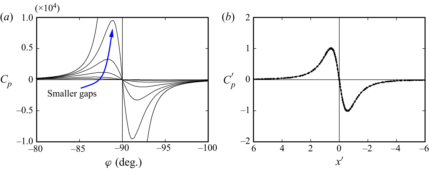
As mentioned above, the size of the gap between the cylinder and the wall has a significant effect on the pressure forces acting on the cylinder. A series of simulations was carried out at a finite Reynolds number of  $\overline {Re}=50$, for which the flow is still steady and the cylinder rolls at constant speed, in order to investigate the evolution of these forces as the gap size approaches zero. Figure 2(a) shows the predicted distribution of the pressure coefficient
 $C_p = (p-p_\infty )/(\frac {1}{2} \rho _f u_c^2)$, for various gap sizes, on the cylinder surface in the vicinity of the gap, whose centre is located at
 $\varphi =-90^\circ$ (see figure 4b for the definition of
 $\varphi$). Decreasing the gap size produces increasing pressure peaks and movement of these peaks towards the centre of the gap. Merlen & Frankiewicz (Reference Merlen and Frankiewicz2011) have used lubrication theory to predict the pressure distribution in this configuration, and proposed scalings for the pressure coefficient and the distance from the gap centre as
 $C_{pm} = 3\sqrt {3}/[2 Re (G/d)^{3/2}]$ and
 $x_m = d ( G/d)^{1/2}$, respectively. Figure 2(b) shows the rescaled distribution
 $C_p' = C_p/C_{pm}$ as function of
 $x' = x/x_m$, showing a collapse of the data. The simulation results clearly match lubrication theory predictions of the pressure distribution in the vicinity of the gap, providing confidence that this near singular region is well predicted by the numerical scheme.
(a) Pressure coefficient distribution in the vicinity of the gap for different gap sizes:  $G/d = 0.005/2^n$,
 $n=0,\ldots ,4$. (b) Rescaled distribution based on lubrication theory (see text for details).
 $\overline {Re}=50$.

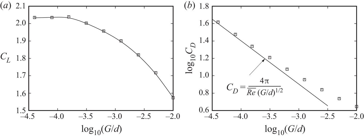
The variation of lift with gap size was not completely explored by Merlen & Frankiewicz (Reference Merlen and Frankiewicz2011). They showed that the lift coefficient increases substantially with decreasing gap size, without showing the behaviour as the gap approaches zero. This variation, obtained for  $\overline {Re}=50$ in the present study, is shown in figure 3(a). The lift approaches an asymptotic value as the gap becomes very small, consistent with the observation that the flow field away from the gap does not appear to be strongly influenced by the gap size as it is reduced to very small values (figure 4). Figure 3(b) shows the drag coefficient as function of gap size. It diverges as the latter approaches zero, in line with the lubrication theory prediction of Merlen & Frankiewicz (Reference Merlen and Frankiewicz2011):
 $C_D = {4{\rm \pi} }/[{Re (G/d)^{1/2}]}$.
Variation of (a) lift coefficient and (b) drag coefficient with gap size. The prediction from lubrication theory in the limit of vanishing gap size is shown by the solid line in (b).  $\overline {Re}=50$.

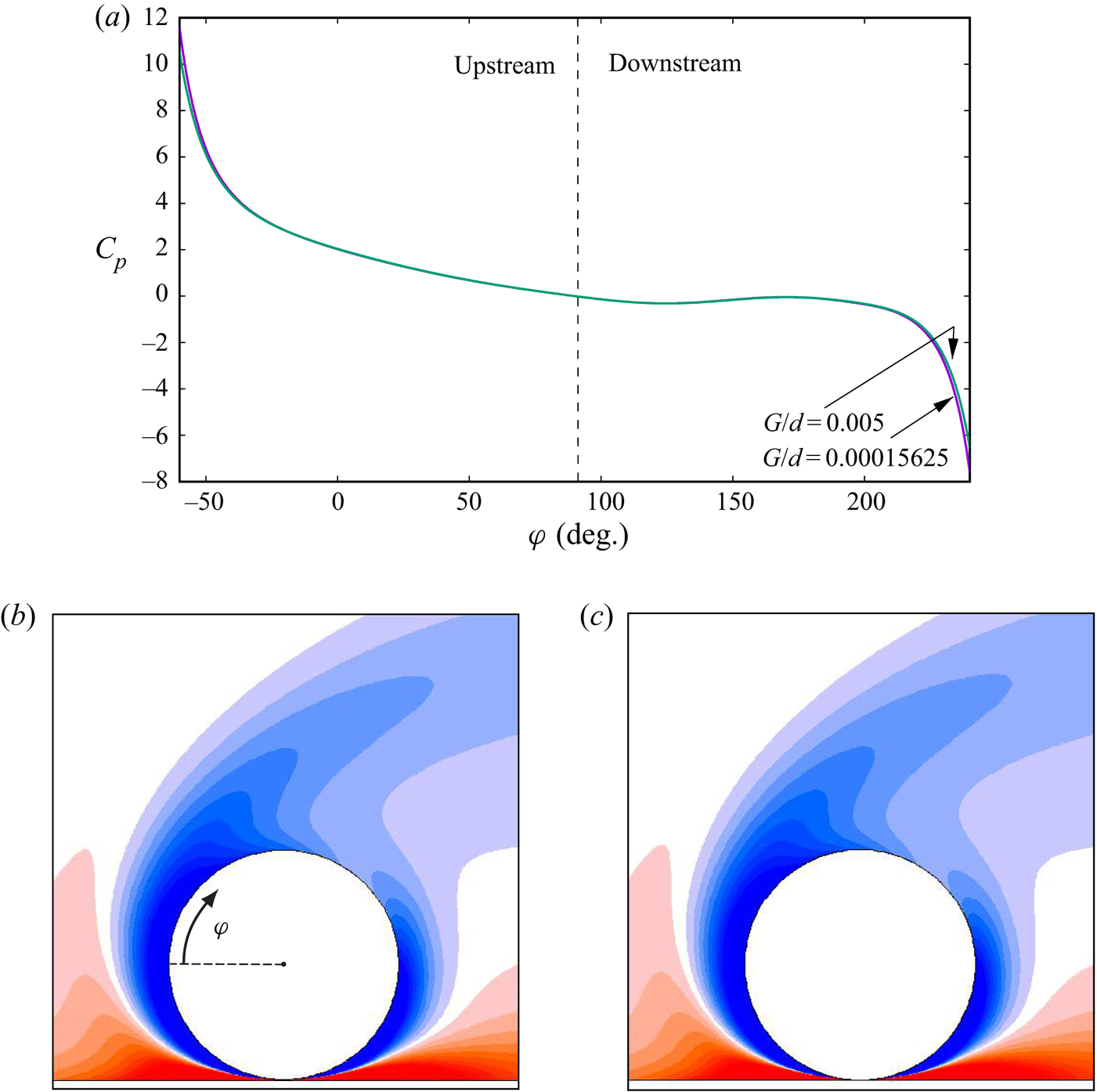
(a) Variation of pressure coefficient at the cylinder surface away from the gap region. The plot shows almost identical distributions for distinctly different gap sizes of  $G/d = 0.005$ and 0.005/32. Panels (b,c) show the vorticity fields in the neighbourhood of the cylinder for these two gap sizes.
 $\overline {Re}=50$.

A premise of the study reported in this paper, and of the previous numerical work by Stewart et al. (Reference Stewart, Thompson, Leweke and Hourigan2010b), Rao et al. (Reference Rao, Stewart, Thompson, Leweke and Hourigan2011) and Houdroge et al. (Reference Houdroge, Leweke, Hourigan and Thompson2017), is that vortex shedding into the wake and flow transitions are only weakly affected by the flow in the vicinity of the gap. Evidence for this is given in figure 4. Panel (a) shows the variation of the pressure coefficient on the cylinder surface away from the gap for two different gap distances of  $G/d = 0.005$ and 0.005/32. The pressure distributions are essentially identical over the top and sides of the cylinder, but begin to diverge as the gap region is approached (see figure 2). Since the pressure gradient along the surface is associated with surface vorticity generation, this indicates that the outer flow does not show a strong dependency on the gap. This is confirmed by panels (b) and (c) in figure 4 comparing the vorticity distributions around the cylinder and in the wake for the two gap sizes. The plotted contour levels are the same in both images, showing the almost identical distributions, despite the reduction in gap size by a factor of 32. Larger differences occur inside the gap, but the overall effect is found to be very localised.
The analysis in this section shows that while the gap size has a strong effect on the pressure distribution in the vicinity of the gap, the influence is effectively localised to that region and negligible elsewhere. The wake states and wake transitions are therefore expected to depend principally on the Reynolds number only. However, the fluid–structure interaction, in which the cylinder responds to the changing drag force as wake vortices are formed and shed, will be affected by the gap size, because the contribution from the gap region to the overall drag dominates the one from the remaining surface as the gap is reduced, i.e. the variation of the wake drag over a cycle is only a fraction of the overall drag for small gaps. These characteristics are examined further in the following sections.
3.2. Added mass
Flow-induced vibration, associated with the formation and shedding of vortices, is expected for higher Reynolds numbers in the present configuration. Since this phenomenon depends on how easy it is to accelerate and decelerate the cylinder, it is worth documenting the added-mass coefficient for this flow, and especially its dependence on the size of the gap. Added mass represents the additional force needed to displace the fluid surrounding an accelerating body, which is given by the drag this body experiences when accelerating in an inviscid potential flow. In practice, a near-potential flow is found at early times when a body accelerates from rest in a quiescent fluid at  $t=0$. Measuring the pressure drag
 $D_p$ in this situation, i.e. neglecting viscous forces, one can therefore estimate the added-mass coefficient as
 \begin{equation} C_A = \lim_{t\to 0}\left(-\frac{D_p}{m_f \ddot{x}_c}\right), \end{equation}
where  $m_f=\rho _f{\rm \pi} d^2/4$ is the displaced fluid mass (per unit span) and
 $\ddot {x}_c$ the acceleration of the rolling cylinder.
This procedure was first tested by accelerating a non-rotating cylinder in a free stream without a wall. The added-mass coefficient obtained in this way,  $C_A=1.00$, is identical to the theoretical potential-flow value for this case, which validates the method.
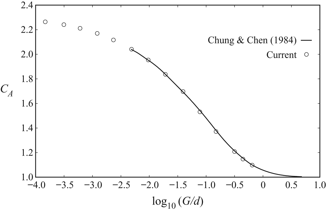
The added-mass coefficient found for the cylinder rolling near a solid boundary is shown in figure 5 as a function of the gap size. Perhaps not surprisingly, this matches the potential added mass for a non-rotating cylinder positioned adjacent to a wall derived by Brennan (Reference Brennan1982) and presented in Chung & Chen (Reference Chung and Chen1984), which is shown by the solid line. The gap clearly has a strong influence on added mass, leading to an increase by a factor of 2 as its size decreases towards zero. Note that the limiting value for zero gap size as given by Brennan (Reference Brennan1982) is 2.290. This high value indicates that the effective oscillatory mass is considerable, even for nominally light cylinders, and may limit the fluid-induced vibration response. It also suggests that the peak vibration amplitude will decrease as the gap size is reduced. This effect is examined in § 5.3.
Added-mass coefficient as a function of gap size. The solid line corresponds to the added mass for a non-rotating cylinder adjacent to a wall. See text for further details.

4. Transition to unsteadiness
In previous studies examining cylinders rolling at fixed prescribed velocities (Stewart et al. Reference Stewart, Thompson, Leweke and Hourigan2010b; Rao et al. Reference Rao, Stewart, Thompson, Leweke and Hourigan2011; Houdroge et al. Reference Houdroge, Leweke, Hourigan and Thompson2017), the transition from two-dimensional steady to unsteady flow was found to occur at  $Re \simeq 88$. The stability analysis for the freely rolling case described in § 2.3 was used to investigate the influence of the cylinder density ratio on this transition. Another question is whether allowing the cylinder to respond to the incipient unsteady flow can alter the critical Reynolds number for transition. Since the present configuration does not involve a resonance between flow unsteadiness and a mechanical frequency, such as for an elastically mounted cylinder in a free stream (Mittal & Singh Reference Mittal and Singh2005), the change in the transition Reynolds number, if any, might be expected to be small.
Equation (2.22) indicates that the standard stability equations are modified by the inclusion of an extra term involving the drag and torque acting on the cylinder. This term is inversely proportional to the cylinder density, hence its contribution diminishes as the density ratio  $\beta =\rho _c/\rho _f$ increases. This is consistent with the expectation that a heavy cylinder will only exhibit a small dynamic response as the flow undergoes transition to unsteadiness, suggesting that the critical Reynolds number will approach that for the fixed-rolling case. For small density ratios, the situation is less obvious.
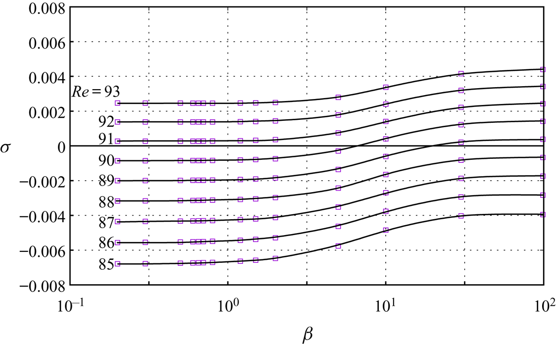
Figure 6 shows the predicted growth rate of the dominant linear mode near transition as a function of density ratio for different Reynolds numbers. For these calculations, a gap size of  $G/d=0.005$ was adopted. A distinct but small increase in the critical Reynolds number for light cylinders is observed. For the heaviest cylinder tested, corresponding to
 $\beta =100$, the growth rate becomes positive at
 $Re_c =88.6$ – the same critical Reynolds number obtained for a uniformly rolling cylinder (see below). There is a smooth transition to higher critical Reynolds numbers for lighter cylinders, asymptoting to a value of
 $Re_c \simeq 90.8$ for
 $\beta < 1$. Thus, there is a variation in the critical Reynolds number of
 ${\rm \Delta} Re_c \simeq +2$ between the heaviest and lightest cylinders; a small but significant change. This indicates that allowing the cylinder to move in response to the developing perturbation field can actually stabilise it. On the other hand, for heavy cylinders, the increased inertia seems to prevent the cylinder from stabilising the dominant perturbation mode.
Non-dimensional growth rate  $\sigma$ (scaled by
 $u_c/d$) of the most unstable periodic mode as a function of density ratio
 $\beta$ for different Reynolds numbers.

The effect of the cylinder motion on damping the perturbation field can be seen by evaluating the change  ${\rm \Delta} E$ in the area-integrated perturbation energy over one cylinder oscillation period, which is given by
 \begin{equation} {\rm \Delta} E=\int_t^{t+T}\iint_{{\mathcal{V}}}\, \boldsymbol{u}'\boldsymbol{\cdot} \frac{\partial\boldsymbol{u}'}{\partial t} \,\textrm{d}V\,\textrm{d}t. \end{equation}
Using (2.20), this expression becomes
 \begin{align} {\rm \Delta} E & = \int_t^{t+T}\iint_{{\mathcal{V}}}\, \boldsymbol{u}' \boldsymbol{\cdot} \left(- \boldsymbol{u}'\boldsymbol{\cdot}\boldsymbol{\nabla} \boldsymbol{\bar{U}} - \boldsymbol{\bar{U}}\boldsymbol{\cdot}\boldsymbol{\nabla} \boldsymbol{u}' +\frac{1}{\rho_f}\boldsymbol{\nabla} p'-\nu\nabla^2 \boldsymbol{u}'-\frac{\mathrm{d}\boldsymbol{u}'_{\boldsymbol{c}}}{ \mathrm{d} t}\right)\textrm{d}V\,\textrm{d}t \nonumber\\ & = \cdots + \int_t^{t+T}\iint_{{\mathcal{V}}} \left(-\boldsymbol{u}' \boldsymbol{\cdot} \frac{\mathrm{d}\boldsymbol{u}'_{\boldsymbol{c}}}{\mathrm{d} t}\right) \textrm{d}V\,\textrm{d}t. \end{align}
The retained term on the right-hand side represents the energy transfer from the fluid to the cylinder over a cycle. The term was evaluated for  $\beta =0.2$ for
 $Re = 90$, which is above the critical Reynolds number of the fixed-rolling case. Indeed it was negative, indicating that the oscillating light cylinder removes energy from the perturbation field to stabilise it beyond that for the non-oscillating case.
As a cross-check on these predictions, the full fluid–structure problem was simulated for a range of Reynolds numbers around the critical Reynolds number, for  $\beta =0.2$. For
 $Re^*=127$ (
 $\overline {Re} = 89.9$), the flow is found to be steady, whilst for
 $Re^* = 129$ (
 $\overline {Re} = 91.7$), the saturated flow state is periodic. The lower value is above the critical number for a steady rolling cylinder (88.6), but below the critical Reynolds number for the coupled system predicted by stability analysis (90.8). Hence these results are consistent with the coupled stability analysis.
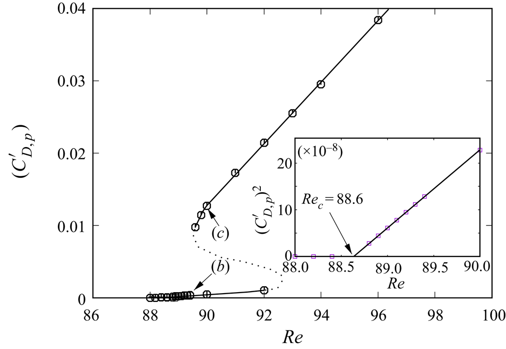
The bifurcation is examined in more detail in figure 7, which shows the amplitude of the fluctuating component of the pressure drag ( $C'_{D,p}$) at saturation for the steady-rolling case in the vicinity of onset. The variation of this amplitude follows two separate branches.A low-amplitude branch exhibits the standard behaviour for a supercritical Hopf bifurcation, i.e.
 $C'_{D,p} \propto (Re - Re_c)^{1/2}$ beyond the critical Reynolds number, which is here found to be
 $Re_c \simeq 88.6$ (see inset of figure 7). A second stable branch of unsteady solutions exists for
 $Re\gtrsim 89.5$. The amplitudes are significantly higher than for the initial branch, and they evolve linearly with Reynolds number. These results show that two stable solutions exist in the approximate interval
 $89.5<Re<92$, beyond which no lower-branch solution could be found. The dotted line in figure 7 qualitatively represents a possible unstable branch connecting the two stable branches.
Bifurcation behaviour near the steady-to-unsteady transition in terms of the variation of the amplitude of the fluctuating component of the pressure drag ( $C'_{D,p}$) at saturation with Reynolds number. These predictions are for the steady rolling case, although a similar variation is observed for the coupled case. For a supercritical Hopf bifurcation, the expected variation is
 $C'_{D,p} \propto (Re-Re_c)^{1/2}$. This behaviour is seen for the lower-amplitude branch close to the critical Reynolds number, as shown in the inset plot. Points labelled (b) and (c) refer to figure 8.

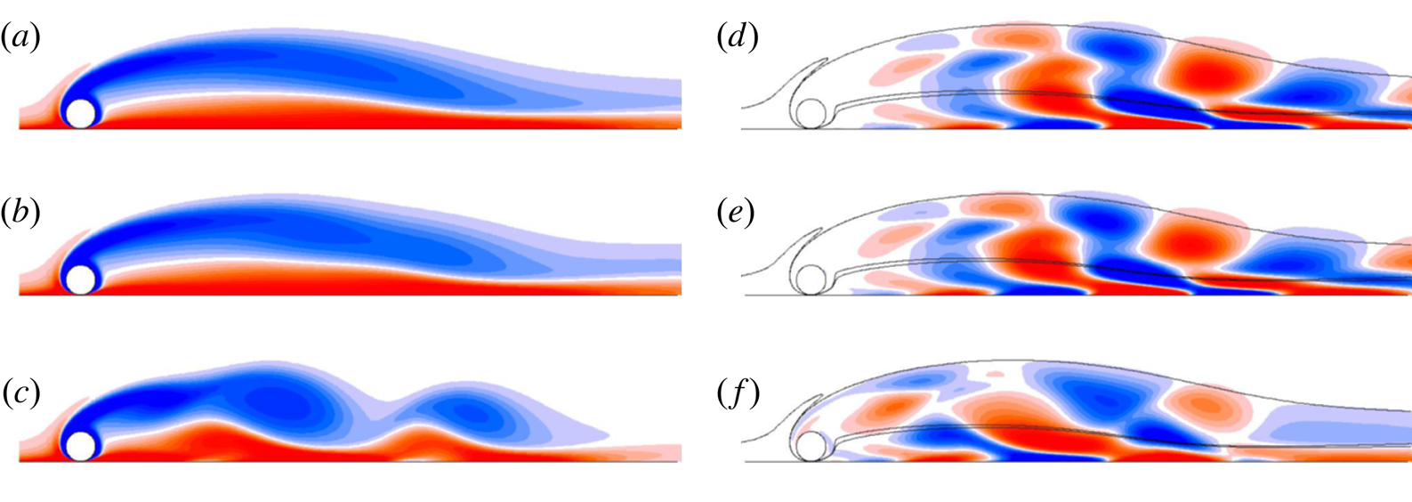
Figure 8 provides a comparison of the perturbation fields close to onset and after saturation. These images correspond again to predictions for the steady rolling cylinder case; similar result are found for the coupled problem. The left-hand column shows the spanwise vorticity field at  $Re = 90$ obtained using a steady solver (figure 8a) and the saturated flow states at
 $Re = 89.4$ and
 $Re=90$ (figure 8b,c), corresponding to points (b) and (c) in figure 7, which lie on different branches of the bifurcation plot. The right-hand column shows the dominant linear stability mode of the steady flow at
 $Re=90$ (figure 8d) and the perturbation fields at saturation for
 $Re=89.4$ and
 $Re=90$ (figure 8e,f), the latter two being obtained by subtracting (b,c) from (a). These images show that, close to onset on the lower branch, the saturated perturbation field is very similar to the dominant linear stability mode. This is not true for slightly higher values of
 $Re$ on the upper branch, for which figures 8(c) and 8(f) show that the saturated perturbation field has departed considerably from the linear stability mode in figure 8(d), further illustrating the difference between the solutions of the two amplitude branches.
Vorticity fields for the steady rolling cylinder. (a) Steady solution at  $Re = 90$; (b,c) saturated unsteady flow at
 $Re=89.4$ and
 $Re=90$, respectively; (d) dominant linear instability mode of the steady flow at
 $Re=90$; (e,f) perturbation at saturation for
 $Re=89.4$ and
 $Re=90$; respectively. The lines are contours of the steady vorticity field for
 $\omega _z = \pm 0.1U/d$.

Finally, there is the question of whether the steady–unsteady transition will vary significantly as the gap size is changed. Since, the wake stability is primarily a function of the wake flow, which is only weakly affected by the flow near the gap, it seems probable that altering the gap should hardly affect the critical Reynolds number, for the constant-speed case. The results from this section show that, for the fully coupled problem, there is only a small variation from that critical Reynolds number for very light spheres. For heavy spheres, due to their increased inertia, the effect is even smaller. As shown in figure 13 below and discussed in detail later, the vibration amplitude appears to be close to maximal for the current gap of  $G/d = 0.005$. Hence, it seems probable that the change in critical Reynolds number is also close to maximal for this gap size.
5. Asymptotic flow characteristics as function of gap size
This section presents results concerning the long-term asymptotic flow states, once the cylinder has reached a steady or periodic state after starting to roll from rest, with special attention to the influence of the gap size. The characteristics of the start-up transient are treated in § 6.
5.1. Translation velocity and Reynolds number
The flow past a uniformly rolling cylinder is governed by a single non-dimensional parameter: the Reynolds number  $Re=Ud/\nu$, based on the diameter of the cylinder and its fixed translational speed. When comparing the results with the freely rolling case, it is useful to resort to the asymptotic Reynolds number
 $\overline {Re}=\bar {U}d/\nu$, where
 $\bar {U}$ is the time-mean speed of the cylinder in the asymptotic state. In § 2.1.4, an alternative Reynolds number was defined specifically for the free-rolling case, based on the velocity scale
 $V$ (2.11) derived from the parameters governing this flow
 \begin{equation} Re^*=\frac{Vd}{\nu}=\frac{1}{\nu}\sqrt{\frac{\textrm{d}^3}{2}|\beta-1|g\sin\theta}. \end{equation}
Multiple simulations were carried out for  $Re^*$ in the range 80–300, density ratios
 $\beta$ between 1.2 and 10 and gap ratios
 $G/d$ from 0.002 to 0.15. The relationship between
 $Re^*$ and
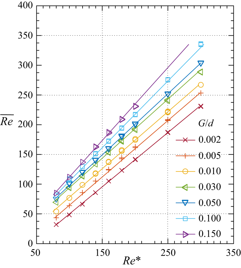
 $\overline {Re}$ is shown in figure 9; it is found to be linear and to depend on the gap size. The two Reynolds numbers are generally close to each other, and almost identical for
 ${G/d=0.05}$. This shows that the derived velocity scale
 $V$ is a good estimate of the asymptotic translation speed of the rolling cylinder.
Relationship between the Reynolds number  $\overline {Re}$ based on the asymptotic (mean) velocity and the modified Reynolds number
 $Re^*$. The different curves correspond to different gap ratios.

These results do not depend on the density ratio  $\beta$. For a fixed
 $Re^*$,
 $\beta$ has virtually no effect on the averaged non-dimensional quantities of the flow at saturation. The influence of the density ratio is entirely accounted for in the non-dimensionalisation, which is based on the momentum balance in the asymptotic state. This parameter does, however, have a significant effect in the transient state starting from rest (see § 6).
5.2. Lift and drag
A cylinder rotating in a uniform flow experiences a lift force (Magnus Reference Magnus1853), which is a direct result of the asymmetrical pressure distribution on the surface of the cylinder generated by the rotation. The presence of a nearby wall reverses the direction of the lift if the cylinder is sufficiently close. Stewart et al. (Reference Stewart, Thompson, Leweke and Hourigan2010b) showed that the lift force increases as the gap ratio is reduced from  $G/d=0.01$ to 0.004 at
 $Re=20\text {--}200$ and for various rotation rates (from normal to reverse rolling), noting that it was of positive sign, i.e. directed away from the wall, over the entire parameter range of their study. For normal rolling, Rao et al. (Reference Rao, Thompson, Leweke and Hourigan2015) extended the analysis to gap heights up to 4 diameters and Reynolds numbers up to 400. One observation was that the lift force becomes negative once the gap exceeds a certain value. This shows that the body can experience either a repulsive or an attractive force from the wall, depending on its distance to it and on the value of the Reynolds number.
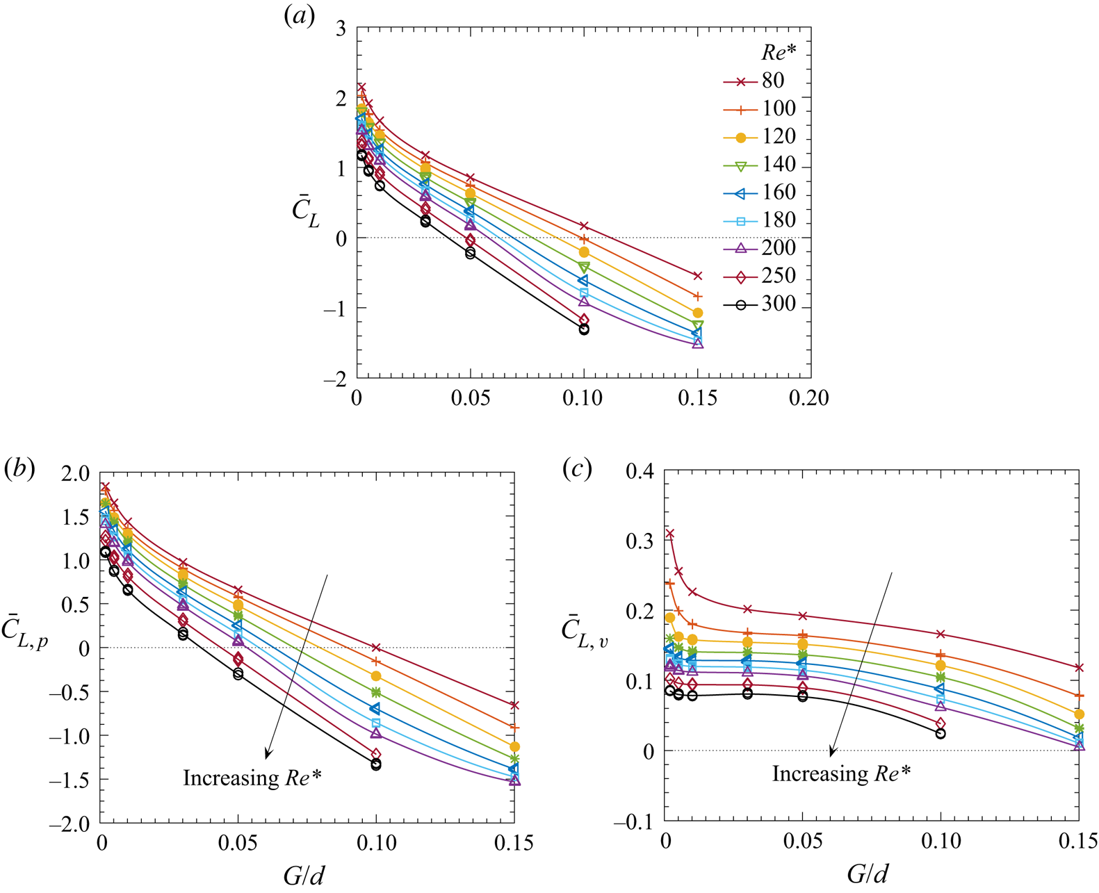
This effect was investigated here for the freely rolling cylinder. The results are reported in figure 10, which shows the total lift, as well as its pressure and viscous components, for  $0.002\le G/d\le 0.15$ and
 $Re^*\le 300$. For
 $Re^*<50$ (not shown), the lift force is found to be positive for all values of
 $G/d$ considered. For higher Reynolds numbers, the expected change of sign occurs. Stewart et al. (Reference Stewart, Thompson, Leweke and Hourigan2010b) noted that, in general, the pressure force, rather than the viscous force, provides the dominant contribution to the lift. As the gap is decreased, the pressure variation across it also increases, as shown in figure 3. The low pressure at the top of the cylinder, together with the complex contribution of the pressure in the gap region, results in a positive lift force. The current simulations show that the change of sign of the total lift is accompanied by a similar change of sign of the pressure lift (figure 10b). The viscous lift remains positive, but fairly constant, contributing less to the total lift variation at a given
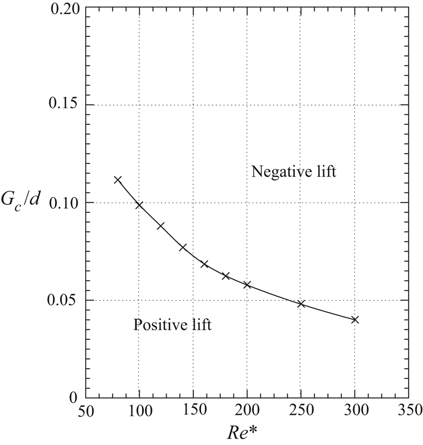
 $Re$ (figure 10c). The wall and the gap region lose their influence as the distance between the cylinder and the wall grows. The forward rolling of the cylinder, combined with the incoming flow at large gap heights, generate a lower velocity magnitude (and therefore greater pressure) on the top of the cylinder than at the bottom, resulting in a pressure differential that causes the lift force to be negative. The relation between the critical gap ratio,
 $G_c/d$, at which the sign change occurs and the Reynolds number is plotted in figure 11.
(a) Mean lift coefficient  $\bar {C}_L$ as a function of the gap size
 $G/d$ for
 $Re^*=80\text {--}300$. (b,c) Pressure and viscous components of the lift force.

Relationship between Reynolds number and critical gap height for the change of sign of the lift force.

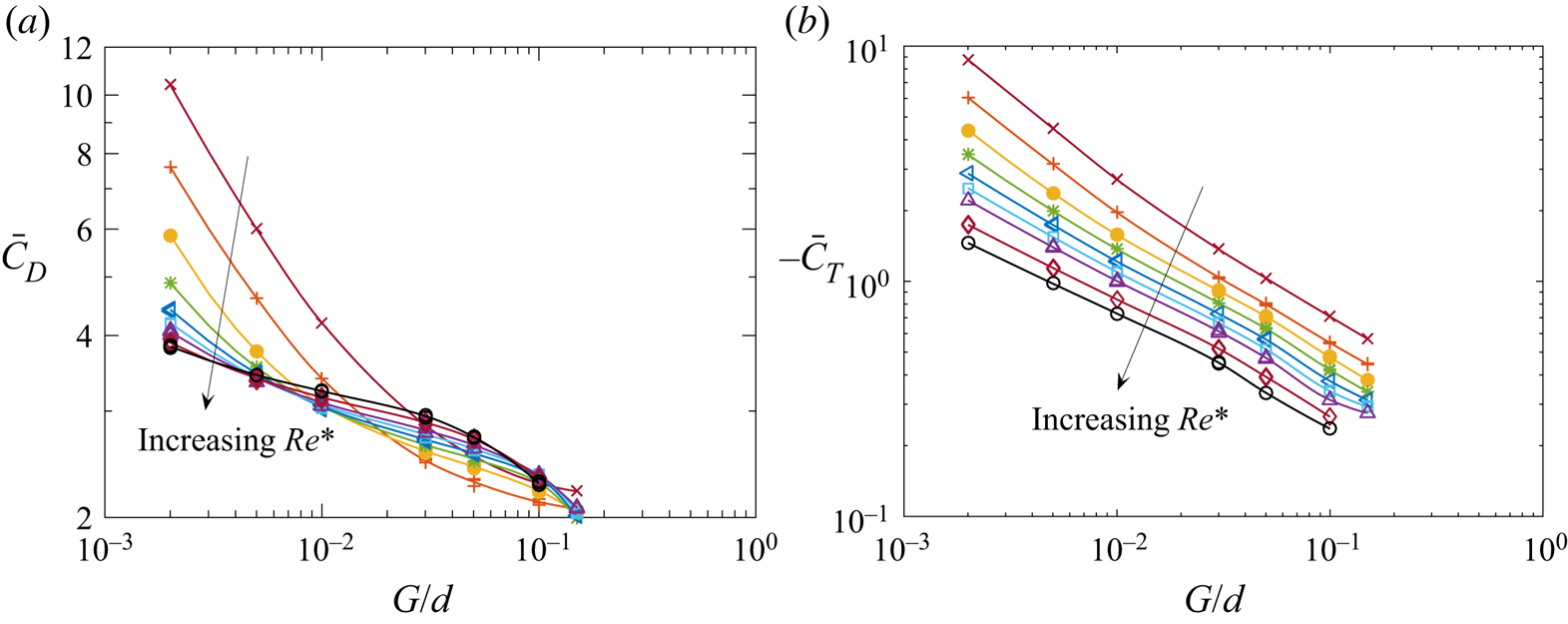
The trends of the mean drag and torque coefficients given in figure 12 show a general decrease in magnitude as the gap ratio increases. Note that, in the chosen coordinate system (figure 1), the fluid torque is negative for a cylinder rolling without slip. Whereas the torque magnitude decreases with  $Re^*$ for all gap sizes, the drag evolution reverses this tendency at larger gaps.
Mean (a) drag coefficient and (b) torque coefficient for  $Re^*\geq 80$ (see legend in figure 10a).

5.3. Amplitude and frequency of oscillations
For Reynolds numbers above the threshold for unsteady flow, the wake of the rolling cylinder reaches a periodic state characterised by vortex shedding (see, e.g. figures 21 and 22 in § 6). The resulting unsteady forces in turn lead to oscillations of the translation velocity of the freely moving cylinder. The frequency  $f$ of these oscillations can be expressed in non-dimensional form as a Strouhal number,
 $St=fd/\bar {U}$. Their amplitude
 $A$ is rescaled by the mean value of the cylinder velocity:
 $A^*=A/\bar {U}$.
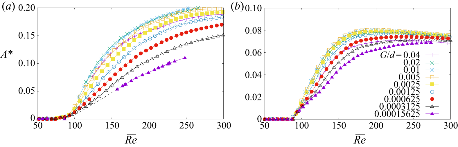
Rescaled amplitudes and Strouhal numbers were determined for a range of gap sizes, Reynolds numbers and density ratios. The results are shown in figures 13 and 14. The gap size has a significant effect on the flow-induced vibration characteristics. The predictions show that as the gap is reduced from  $d/25$ to
 $d/6400$, the vibration amplitude initially increases to peak at a gap ratio around 0.01, before decreasing at smaller gap ratios. Reducing the gap from
 $0.005d$ by a factor of 32 results in a reduction of the vibration amplitude by approximately 50 % for
 $\beta =1.2$, and considerably less in the
 $\beta =10$ case. The data also show that a decrease of the mass ratio from
 $\beta =10$ to 1.2 results in only a moderate overall increase of the velocity fluctuation (factor of 2). This is consistent with the large added mass (
 $C_A \sim 2$) associated with a cylinder rolling near a wall (figure 5).
Amplitude  $A^*$ of velocity oscillations (scaled by the mean velocity). (a)
 $\beta =1.2$, (b)
 $\beta =10$.

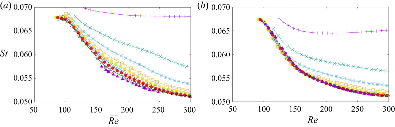
Non-dimensional oscillation frequency  $St$. (a)
 $\beta =1.2$, (b)
 $\beta =10$. Symbols and lines as in figure 13.

The Strouhal number varies with all three parameters as well, although for all the cases considered it lies in the approximate range  $0.05<St<0.07$, with smaller values at higher Reynolds numbers (except for the largest gap,
 $G/d=0.04$). For gap ratios
 $G/d\le 0.005$, the variation with this parameter is weak, especially for high mass ratios. Figure 14(b) for
 $\beta =10$, shows a collapse of the Strouhal–Reynolds number curves for
 $G/d \lesssim 0.0025$. This is consistent with the small variation of vibration amplitude with gap ratio in this parameter range.
The results in this section have clearly shown that the size of the gap between the wall and the cylinder rolling along it has a non-negligible effect on the characteristics of the cylinder motion, the wake flow and the resulting flow-induced vibrations. In order to explore in more detail the dependence on the other parameters, the gap ratio is fixed at  $G/d=0.005$ throughout the remainder of the paper. This is in line with previous similar studies (e.g. Stewart et al. Reference Stewart, Thompson, Leweke and Hourigan2010b; Rao et al. Reference Rao, Stewart, Thompson, Leweke and Hourigan2011) and partly motivated by numerical constraints. Reducing the gap ratio drastically affects the maximum time step of the numerical method, because of the increasingly singular pressure distribution. The chosen gap size is a compromise, enabling a more extensive coverage of parameter space. It produces a VIV response which is close to maximum for small gap ratios, as shown in figure 13. This figure can be used to adjust the VIV predictions made in the following section for cases with different gap sizes.
6. Flow and cylinder motion starting from rest
This section considers the overall evolution of the cylinder motion and the associated wake flow after the body is released from rest. The gap size is fixed at  $G/d=0.005$ and the two parameters governing the evolution of the system, the Reynolds number and the density ratio, are varied.
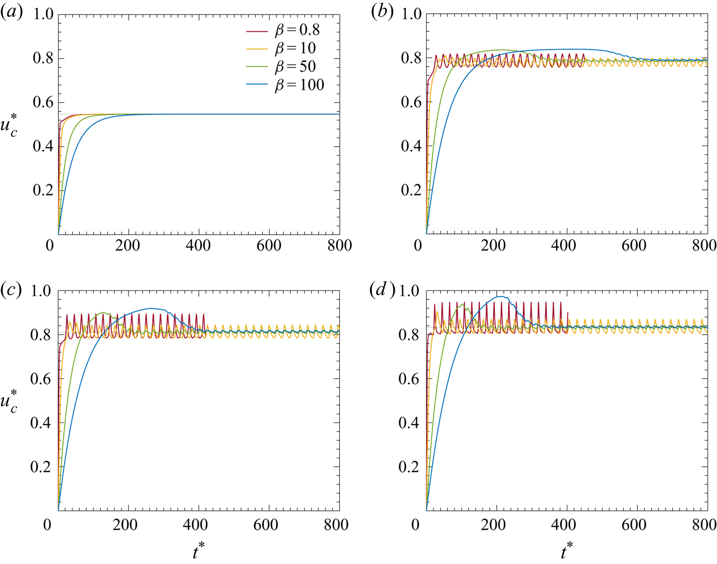
Figure 15 gives an overview of the different behaviours for  $80\le Re^*\le 250$ and
 ${0.8\le \beta \le 100}$, illustrated by the time evolution of the cylinder velocity. For a given Reynolds number, the final (non-dimensional) mean velocity is the same for all values of the density ratio, which is expected from the choice of the scaling. However, the start-up transient and the amplitude of flow-induced vibrations in the final state vary with
 $\beta$. The period of oscillation depends primarily on the vortex shedding frequency of the uniformly rolling case, which is only weakly modified by the vibration of the cylinder; it is nearly the same for all values of
 $\beta$.
Temporal evolution of the cylinder velocity for different Reynolds numbers and density ratios.  $(a) \ Re^{\ast} = 80, \ (b) \ Re^{\ast}= 160, \ (c) \ Re^{\ast} = 200, \ (d) \ Re^{\ast} = 250$.

From figure 15, one can identify distinct phases in the motion history starting from rest. Initially, the cylinder velocity increases from zero with an almost constant acceleration, which is a function of the density ratio. Subsequently, it continues to increase and fluctuate on a time scale not related to vortex shedding, before reaching, or oscillating around, a constant speed.
6.1. Initial evolution
At small times, the drag force is dominated by the added mass contribution, as mentioned in § 3.2. The equation of motion (2.10) therefore reduces to
 \begin{equation} \tfrac{3}{2} m_c \ddot{x}_c = |m_c - m_f| g \sin\theta - C_A m_f \ddot{x}_c. \end{equation}
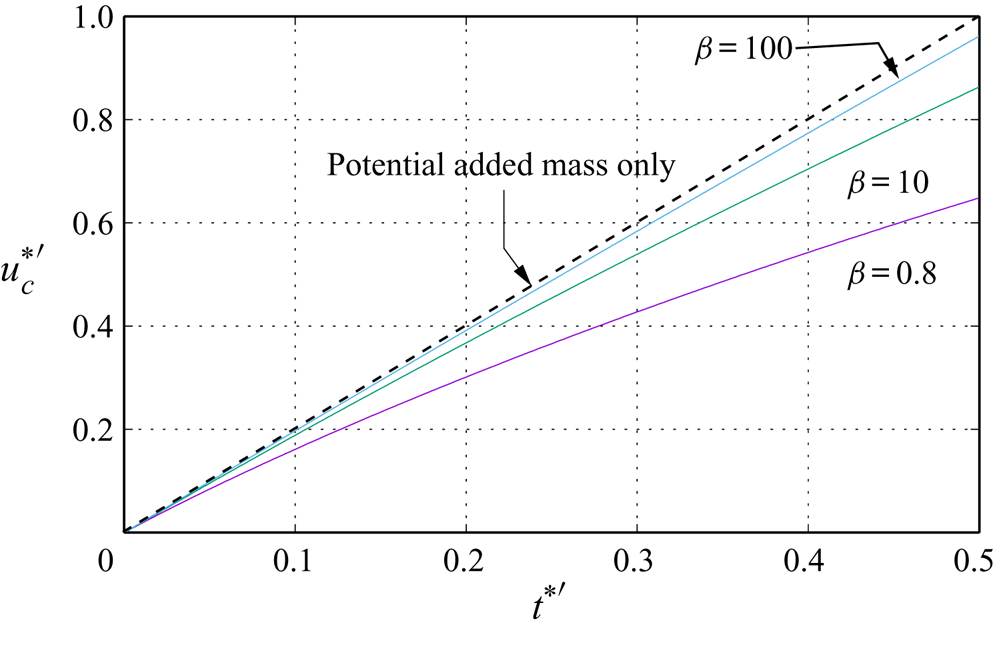
Scaling the velocity by  $V' = V/\sqrt {(3/2)\beta +C_A}$ and time by
 $\tau ' = (d/V)\sqrt {(3/2)\beta +C_A}$, reduces (6.1) to the dimensionless equation
 ${\textrm {d}{u}_c^*}^\prime /{\textrm {d}t^*}^\prime = 2$. Using this scaling should result in a collapse of the dimensionless velocity–time variation at small times. This is demonstrated in figure 16, which shows the rescaled velocity evolution at
 $Re^* = 200$ for three values of
 $\beta$. The evolutions follow the prediction of (6.1) at very small times. As the cylinder accelerates and vortical structures develop in the wake, the effective added mass rapidly deviates from the potential added mass. For low mass ratios, this has a large effect on the cylinder acceleration, while for high mass ratios, the influence of the added mass is relatively small.
Variation of the rescaled velocity with rescaled time at  $Re^* = 200$ for different mass ratios, showing the collapse of the curves for small times.

6.2. Intermediate phase
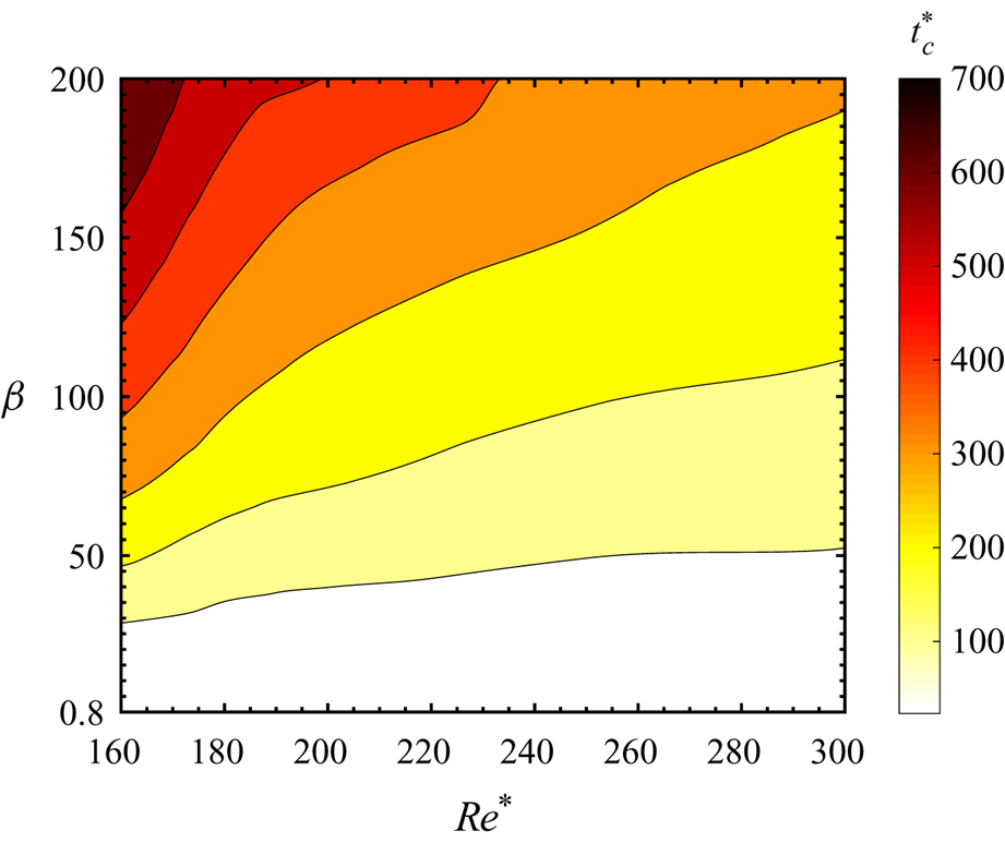
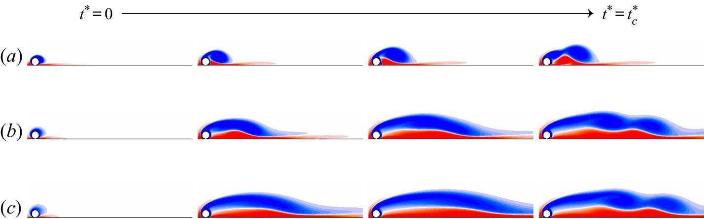
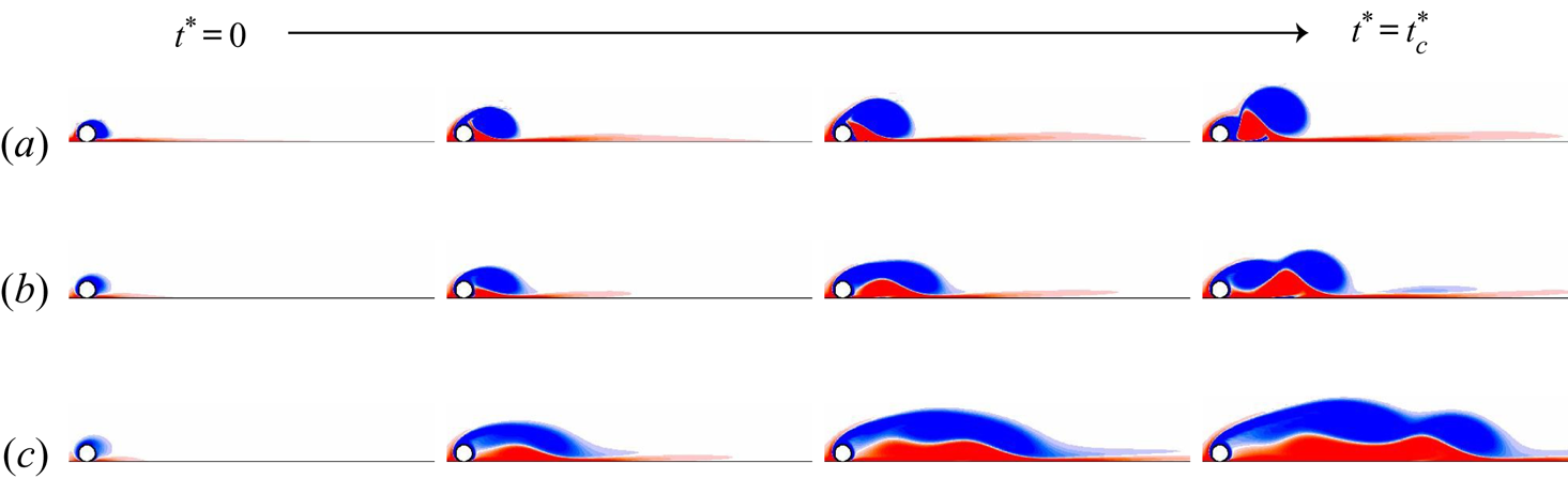
For Reynolds numbers below the threshold for unsteady flow (figure 15a), the cylinder motion reaches its asymptotic state with constant velocity after a smooth transition from the initial acceleration phase. The duration of this transition increases with the density ratio, as expected. When the flow is unsteady, we define the critical time  $t^*_c$ as the non-dimensional time corresponding to when the first vortex is shed into the wake, specifically calculated from the time of the initial local maximum of the cylinder velocity. Figure 17 contains a contour plot of
 $t_c^*$ as a function of
 $Re^*$ and
 $\beta$, and figures 18 and 19 compare the evolution of the wake from
 $t^*=0$ to
 $t^*=t^*_c$ for two Reynolds numbers and three density ratios. Figure 17 shows that
 $t_c^*$ increases as
 $Re^*$ decreases and/or
 $\beta$ increases; the closer to transition and/or the denser the body, the longer the duration of the intermediate phase. Regarding the flow structure, the recirculation region that forms and develops downstream of the cylinder prior to the shedding of vortices is quasi-steady and characterised by two closed recirculation zones: an upper one forming around the cylinder and being displaced away from the wall (coloured in blue), and a lower one which is smaller and forms near the wall (coloured in red). These regions grow longer as
 $Re^*$ decreases and/or
 $\beta$ increases.
Characteristic time  $t_c^*$ for the onset of vortex shedding, as function of Reynolds number and density ratio.

Initial development of the flow (vorticity contours) up to the shedding of the first vortex at time  $t_c^*$, for
 $Re^*=160$ and different density ratios.
 $(a)\ \beta = 0.2, \ (b) \ \beta = 50, \ (c) \ \beta = 200.$

Same as figure 18, for  $Re^*=300$.
 $(a)\ \beta = 0.2, \ (b) \ \beta = 50, \ (c) \ \beta = 200$.

Low mass ratios result in the transition to unsteady periodic flow almost as soon as the separating shear layer has rolled up into a small identifiable vortex structure. On the other hand, large mass ratios allow a quasi-steady intermediate wake to form prior to the onset of strong unsteadiness and vortex shedding. This elongated recirculation bubble is similar to the solution obtained by solving the steady flow problem at the same Reynolds number. Presumably, this happens because of the slow increase in cylinder velocity at high mass ratios, allowing the wake to evolve slowly through a series of near-steady wake states. During this transition, the cylinder reaches velocities well beyond the mean velocity of the final state. This behaviour is similar to the one observed for an isolated cylinder in a free stream. When shedding commences, it takes many cycles for the wake to shorten again, and for the cylinder to decrease its velocity to reach the asymptotic state.
6.3. Asymptotic state
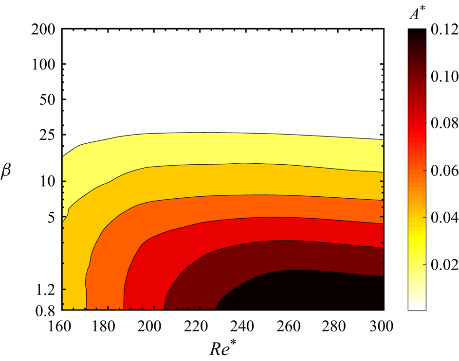
In the final state, the wake and cylinder motion are either steady (figure 15a) or periodic (figure 15b–d). The amplitude of the velocity oscillations (figure 20) decreases as the density ratio  $\beta$ increases and/or
 $Re^*$ decreases: the denser the body, the less sensitive it is to the forces acting on it; and the weaker the vortex shedding, the lower these forces are. Both effects lead to a weaker response and oscillation amplitude. Figures 21 and 22 compare the flow evolution at
 $\beta =0.2$ and 200 for
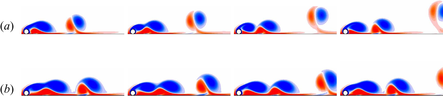
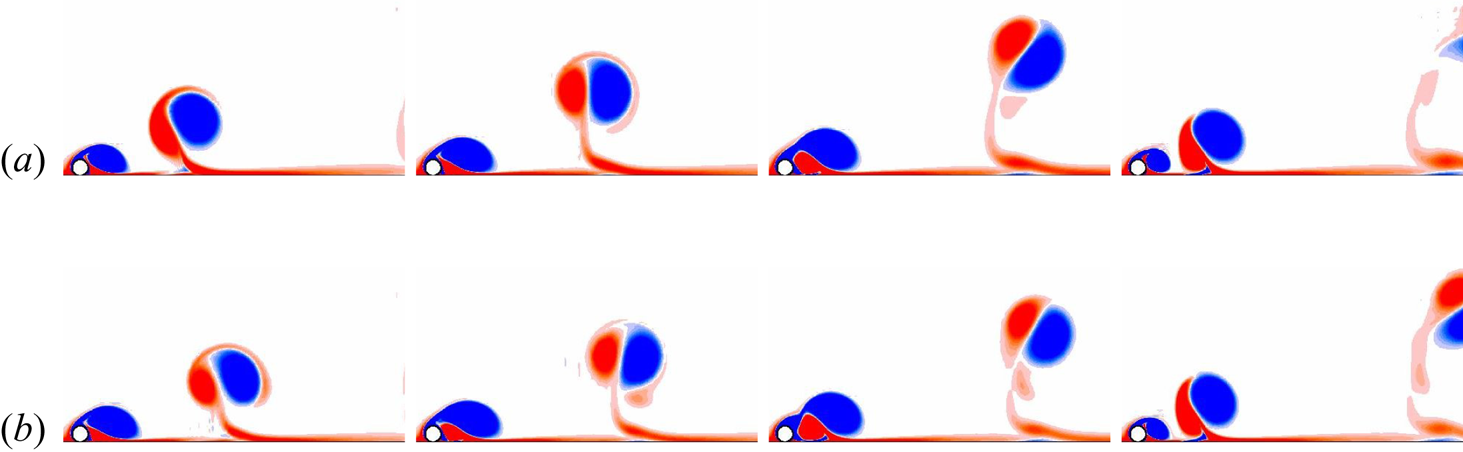
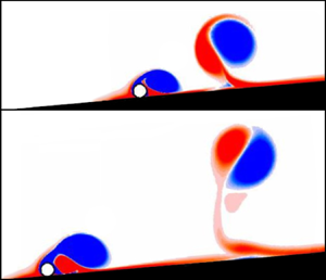
 $Re^*=160$ and 300, respectively, over one shedding cycle. The shedding patterns are similar: a compact vortical structure forms from the upper shear layer, destabilises the wall shear layer and rolls up to shed as a counter-rotating vortex pair. One can nevertheless distinguish that for the heavier cylinder (
 $\beta =200$), the vortices are closer to the wall than for the lighter one (
 $\beta =0.2$).
Amplitude  $A^*$ of cylinder velocity oscillations (scaled by the mean velocity), as a function of Reynolds number and density ratio.

Flow evolution during one shedding cycle for  $Re^*=160$.
 $(a)\ \beta = 0.2, \ (b) \ \beta = 200$.

Same as figure 21, for  $Re^*=300$.
 $(a)\ \beta = 0.2, \ (b) \ \beta = 200.$

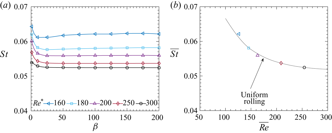
The Strouhal number of the unsteady asymptotic states is shown in figure 23(a) as function of the density ratio for various Reynolds numbers. Some dependency on  $\beta$ can be observed for
 $\beta <50$; above this value, the Strouhal number is practically constant. Heavier cylinders show weaker flow-induced vibrations and therefore roll with approximately the same constant non-dimensional speed, since the latter does not depend on
 $\beta$. As a consequence, the measured mean Strouhal numbers for
 $\beta >50$ are in good agreement with the results obtained for uniform rolling, as seen in figure 23(b), where the Reynolds number
 $\overline {Re}$ is used for comparison purposes. The values lie between 0.05 and 0.065 for
 $100<\overline {Re}<300$, which is significantly lower than for a non-rotating cylinder in an unbounded flow.
(a) Strouhal number as function of density ratio for different Reynolds numbers. For  $\beta \ge 50$, the Strouhal number is practically constant. Its mean value
 $\overline {St}$ in this range is shown as function of
 $\overline {Re}$ in (b) and compared to the uniform-rolling case.

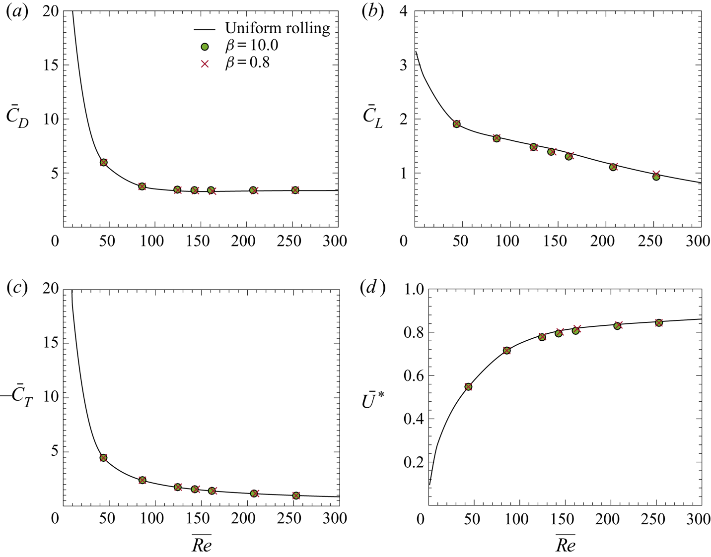
Further comparisons can be made between the asymptotic state of the freely rolling cylinder and the case of a cylinder rolling at constant speed, again using  $\overline {Re}$. Figure 24(a–c) compares the time-mean drag, lift and torque coefficients obtained in both cases. The values match closely up to the transition at
 $\overline {Re} \simeq 88$, where the flow becomes unsteady and the freely rolling body begins to oscillate. In the unsteady regime, deviations of less than 2 % for the drag and torque and 5 % for the lift occur. Using the force and torque data, (2.18) can be used to predict the asymptotic mean velocity of the freely rolling cylinder. This prediction is compared to the values measured in the simulations in figure 24(d), showing excellent agreement.
Mean (a) drag, (b) lift and (c) torque coefficients. The lines show the results for uniform rolling. (d) Asymptotic mean velocity. The line represents the prediction in (2.18).

6.4. Flow-induced vibrations
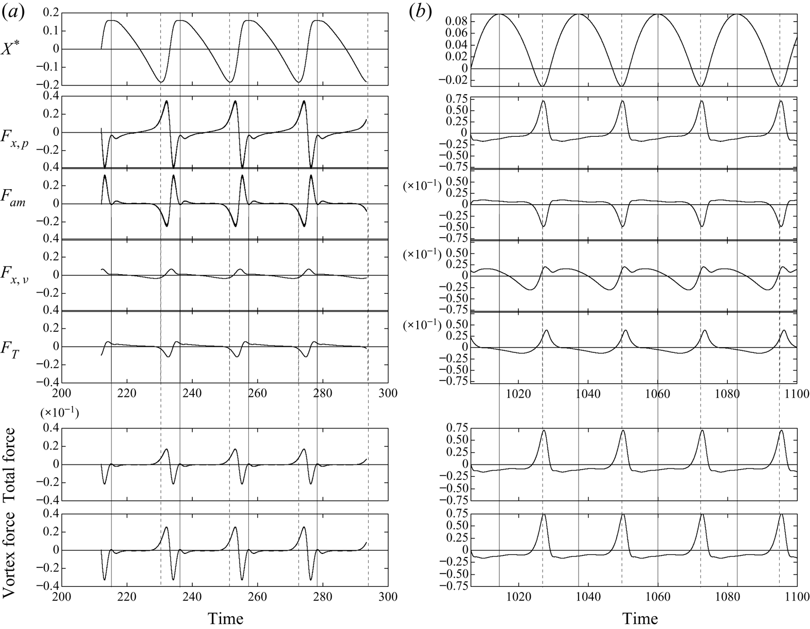
In this section, we take a closer look at the various time-dependent forces acting on the freely rolling cylinder in the unsteady regime, characterised by vortex-induced vibrations. The top row of figure 25 shows the asymptotic oscillatory cylinder displacement around its linearly increasing mean position,  $X^*= (x_c-\bar {U}t)/d$, as a function of time for
 ${Re^*=250}$. The left and right columns show results for
 $\beta =0.1$ and 20, respectively. Both displacement signals are far from sinusoidal, and the displacement for the low mass ratio is markedly asymmetric, almost resembling a sawtooth waveform. The oscillation amplitude is significantly greater for
 $\beta = 0.1$, as might be expected, with a value of
 ${\sim } 0.17d$. For
 $\beta =20$, the amplitude is less than half this value.
Time histories of the oscillation amplitude and force components for  $Re^*=250$ and two density ratios. From top to bottom, the figure shows:
 $X^*$ – cylinder displacement with respect to the motion at constant mean velocity;
 $F_{x,p}$ – pressure force coefficient without added mass;
 $F_{am}$ – added-mass force coefficient;
 $F_{x,\nu }$ – viscous force coefficient;
 $F_T$ – force coefficient from torque; total force coefficient; and vortex force coefficient.
 $(a)\ \beta = 0.1, \ (b) \ \beta = 20$.

Figure 25 also shows the time traces of the force components acting on the cylinder, and their phase relationships to the displacement signal. From (2.10), the dimensional equation of motion can be written as
 \begin{equation} \tfrac{3}{2} m_c \ddot{x} = |m_c - m_f| g \sin\theta + F_x + 2 T /d, \end{equation}
where  $F_x = -D$ is fluid force in the
 $x$-direction, and
 $T$ is the viscous torque. Splitting the fluid force
 $F_x + 2T/d$ into different physical contributions gives
 \begin{align} \textrm{fluid force} &= (F_p + C_A m_f \ddot{x}) - C_A m_f \ddot{x} + F_{x,\nu} + 2 T/d\nonumber\\ &= F_{x,p} + F_{am} + F_{x,\nu} + F_T. \end{align}
Here,  $F_{x,p}$ is the pressure force without the added-mass contribution,
 $F_{am}$ the (potential-flow) added-mass term associated with the acceleration of the cylinder,
 $F_{x,\nu }$ the viscous drag force, and
 $F_T$ the effective forcing due to viscous torque. In an attempt to examine contributions from irrotational and rotational flow components, Govardhan & Williamson (Reference Govardhan and Williamson2000), following Lighthill (Reference Lighthill1986), considered the total force to consist of the potential added-mass force and a ‘vortex force’ representing all other contributions
 \begin{equation} F_{total} = F_{am} + F_{vortex}. \end{equation}
For the classical VIV response of a circular cylinder, the transitions to different modes can be identified with different jumps in the total and vortex force components as the flow velocity is varied.
Figure 25 shows these contributions for  $\beta =0.1$ and
 $\beta =20$. For both cases, the total and vortex force signals are approximately
 $180^\circ$ out of phase with the displacement signal. This was verified by performing a Hilbert transform on each signal and subtracting the time-dependent phases to obtain a mean value (see, e.g. Khalak & Williamson Reference Khalak and Williamson1999). For the low mass ratio case, the total force is small relative to the vortex force, because the pressure force consists mainly of the added-mass component. The viscous force terms
 $F_{x,\nu }$ and
 $F_T$ are relatively small in comparison, as expected, given the mean Reynolds number of 250. The situation for
 $\beta =20$ is different. Here the added mass, viscous and viscous torque terms are an order of magnitude smaller than the pressure term, so that the vortex and total force signals are very close. One interesting comparison concerns the viscous torque term. The phase relationship switches between the low and high mass ratio cases from being approximately in phase to being approximately out of phase with the displacement signal.
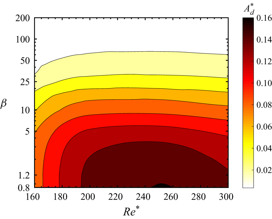
Figure 26 shows a contour plot of the displacement amplitude over a wider range in the  $Re^*$–
 $\beta$ parameter space. Peak amplitudes occur for
 $200 \leq Re^* \leq 250$ as
 $\beta$ is varied over several orders of magnitude. The largest values occur for lighter-than-fluid mass ratios, as might be expected. However, because of the large added-mass coefficient, the oscillation amplitudes are limited, even for very light cylinders.
Amplitude  $A_d^*$ of the displacement oscillations (scaled by the cylinder diameter) as a function of Reynolds number and density ratio.

7. Conclusions
We have studied the configuration of a circular cylinder rolling along an inclined solid wall in a viscous incompressible Newtonian fluid under the influence of gravity, through two-dimensional numerical simulations. The evolution equations for the fluid and cylinder motion depend on two non-dimensional parameters: a Reynolds number based on a velocity scale derived from the balance between gravity and fluid forces in the asymptotic state, and the ratio of cylinder and fluid densities. In addition, the size of the small but finite gap between the cylinder and the wall, which is required by the numerical procedure, has a notable effect on the fluid forces. It is known from lubrication theory that the drag on the rolling cylinder diverges as the gap is reduced to zero, and the corresponding theoretical scaling is recovered in the present simulations. The lift, torque and added-mass force also increase with decreasing gap size, although they appear to remain finite. For small gap size (less than 1 % of the cylinder diameter), the added mass of the rolling cylinder is more than twice that of a non-rotating cylinder far from a wall. The gap effect remains localised in the immediate vicinity of the location of minimum cylinder–wall separation. The pressure distribution on the outer parts of the cylinder wall and the overall vorticity distribution near the cylinder and in its wake are quite insensitive to variations in the gap size, provided the latter is small enough.
Increasing the Reynolds number leads to the onset of unsteadiness in the wake of the rolling cylinder. Whereas for heavy cylinders (large density ratios), this transition occurs at roughly the same velocity as for a cylinder rolling at a prescribed fixed speed, the instability threshold is found at higher Reynolds numbers in the case of light cylinders. The fact that the cylinder is free to adjust its motion to the forces acting on it delays the transition to unsteadiness for low density ratios. For comparison/contrast, one may recall the case of a non-rotating elastically mounted cylinder in a free stream, for which the added degree of freedom leads to vortex-induced vibrations at Reynolds numbers below the threshold for unsteadiness of the fixed cylinder (Mittal & Singh Reference Mittal and Singh2005).
Once the wake is unsteady, the cylinder responds to the time-dependent forces with periodic oscillations of its rolling speed. The amplitudes and frequencies of these flow-induced vibrations depend on both the Reynolds number and the density ratio, as well as on the gap size. In the long-term asymptotic state, the time-averaged force and torque coefficients, as well as the wake frequency, are nearly identical to the values found for a cylinder rolling at constant speed. This can be explained by the fact that the oscillation amplitudes generally remain small, even for low density ratios, due to the large added mass in this configuration.
Whereas the mean values of the forces and non-dimensional rolling speed in the asymptotic state do not depend on the density ratio, this parameter influences the stages leading up to this regime after a start of the motion from rest: the initial acceleration with near-potential flow and the subsequent growth of a recirculation region before the onset of vortex shedding. The duration of these phases, as well as the amplitudes of the final flow-induced vibrations, are affected by the density ratio. For high values, the initial acceleration is slower, allowing the near-wake vorticity region to grow and move downstream. This leads to a significant overshoot of the cylinder velocity with respect to the final asymptotic value. At low mass ratios, this phase is much shorter and without overshoot, since shedding commences quickly.
We have not addressed the issue of cylinder lift-off from the wall, the cylinder motion being restricted to the direction parallel to the wall in our simulations. Since the lift (force in the direction normal to the wall) is generally positive in the range of parameters considered here, reaching relatively large values for small gap sizes, the situation may arise that this lift exceeds the component of gravitational/buoyancy force normal to the wall, which would lead to a negative wall reaction force ( $N$ in (2.6)). Since this is not possible, the cylinder does not remain at its original distance from the wall (gap), but accelerates away from it. Using the condition
 $N<0$ and the expression (2.18) for the asymptotic velocity, one can derive the following condition for lift-off:
 \begin{equation} \tan\theta > \frac{\bar{C}_D-\bar{C}_T}{\bar{C}_L}, \end{equation}
where the right-hand side depends only on the Reynolds number. When  $Re^*$ is fixed, the cylinder is expected to lift off when the wall inclination angle exceeds a limit depending on the values of the (mean) force and torque coefficients. An alternative interpretation results from the fact that the lift is a decreasing function of the gap size: when the limit for lift-off is reached, the cylinder will move away from the wall, but just enough so that the lift coefficient associated with the new gap size is again below the limit for lift-off.
Following on from this discussion, the next stage would be to produce a coupled model that allows for normal motion of the cylinder without a fixed gap. However, including this further degree of freedom increases the problem complexity substantially; in particular, the flow physics within the gap operates on much shorter time and length scales than the outer flow, so a multi-scale modelling approach treating the two zones using different approaches may provide a way forward. Even with the current model, for minute gaps a minuscule time step is needed, resulting in extremely long integration times. Adding this further degree of freedom also decouples the rolling and translating velocities, and in addition, means that a time-varying mesh (or alternative approach) would be needed. In reality, the gap thickness for an ideal cylinder is probably mostly dependent on surface roughness, which ideally would also be included in the computational model. Finally, we note that for smooth machined cylinders, the effective gap is likely be to significantly smaller than the smallest gap considered in this study.
We have also not considered three-dimensional effects. As discussed in Houdroge et al. (Reference Houdroge, Leweke, Hourigan and Thompson2017), for a cylinder rolling at fixed speed, the transition to three-dimensional flow first occurs for the steady two-dimensional wake, at Reynolds numbers below the instability threshold leading to two-dimensional shedding. A similar behaviour is expected for the freely rolling cylinder if the third, spanwise dimension is added. Three-dimensional instabilities will then interact with, and modify, the unsteady transition and the flow-induced vibration characteristics. For the case of a cylinder starting its motion from rest, the system traverses a series of different quasi-steady states with increasing Reynolds number (based on the instantaneous speed). This process tends to delay the three-dimensional transition, similar to the case of a cylinder which starts to roll impulsively at a constant speed (Houdroge et al. Reference Houdroge, Leweke, Hourigan and Thompson2017).
Acknowledgements
This research was supported by Australian Research Council Discovery Project grants DP150102879 and DP200100704. We also acknowledge computing time support through the National Computational Infrastructure (NCI) and the Pawsey Centre through National Computing Merit Allocation Scheme (NCMAS) computing time grants D71 and N67.
Declaration of interests
The authors report no conflict of interest.