I. INTRODUCTION
The increased trend for higher strength and formability has led to the development of a number of multiphase steels such as: (i) dual-phase (DP) steels that consist of ferrite and martensite, (ii) transformation induced plasticity (TRIP) steels that consist of ferrite, bainite, and retained austenite, (iii) “tri phase” steels that consist of ferrite, martensite, and a small amount of bainite, and (iv) bainitic steels that consist of bainitic ferrite and retained austenite/martensite. These types of steels emphasize the control of the nonferrite phases, whereas conventional microalloyed steels focus on the control of the ferrite grain size and precipitation hardening. Among the different approaches, grain refinement is the key technique to simultaneously improve strength and toughness in metals. For example, the novel thermomechanical processing routes to produce ultrafine ferrite (UFF) with a size of 1–4 μm and cementite particles has recently been developed by our group.Reference Hodgson[1] However, extreme ferrite refinement results in the yield stress approaching the value of the tensile strength, producing flat stress–strain curves (i.e., little work hardening).Reference Hodgson[1,Reference Beladi, Kelly and Hodgson2] To overcome this problem, we suggested to form a hybrid microstructure containing UFF and the second hard phase, as in case of the DP steels. One of the choices for the second phase was suggested to be a low temperature bainite.
Recently, there has been significant interest in the bainite reaction at very low temperatures (200–350 °C). Careful alloy design (0.79C–1.5Si–1.98Mn–0.98Cr–0.24Mo–1.06Al–1.58Co wt%), makes it is possible to achieve a fully nanobainitic microstructure with ultrafine or nanolayers of bainitic ferrite (60–400 nm) and retained austenite (30–70 nm).Reference Bhadeshia[3–Reference Timokhina, Beladi, Xiong, Adachi and Hodgson5] The volume fraction of the retained austenite can be in the range of 20–50%. The nanobainitc steels showed a high level of strength (up to 2.2 GPa), however, because of the difficulties associated with the control of retained austenite stability, the ductility did not meet the requirements.Reference Bhadeshia[3,Reference Caballero and Bhadeshia4] Other disadvantages of this steel are the high alloying additions, long isothermal heat treatment times (up to 2 weeks) and mechanical properties that are very sensitive to the isothermal treatment parameters. In this research, we propose to use the advantages of UFF and low bainite microconstituents by combining the UFF and low temperature nanobainite, as in the conventional TRIP steel microstructure, to form a hybrid microstructure to produce a high work hardening rate together with a unique combination of ultimate tensile strength and elongation. To a large extent, the properties of the TRIP steels are determined by the interaction of the phases present in the microstructure, as well as by the TRIP effect,Reference Zackay, Parker, Fahr and Bush[6,Reference Speich, Demarest and Miller7] i.e., the formation of martensite from the retained austenite in response to the applied load.Reference Zackay, Parker, Fahr and Bush[6,Reference Gerberich, Hemmings, Merz and Zackay8–Reference Tamura12] The macroscopic plastic strain accompanying the austenite-to-martensite phase transformation under stress is defined as transformation plasticity. The strain can arise from the transformation shape change (preferential formation of favored crystallographic variants) and/or plastic accommodation processes, which occur around martensitic islands as they form (i.e., from biasing of accommodation slip, triggered by both the volume change and the transformation shear).Reference Bhandarkar, Zackay and Parker[13–Reference Olson and Cohen16] The formation of hybrid microstructure can also maximize the amount of the retained austenite with optimum stability because the first carbon enrichment of the retained austenite occurs during the austenite-to-ferrite transformation. An increase in the C content of retained austenite, as a result of ferrite formation before the bainite transformation, retards both bainite and martensite formations, as it decreases the driving force for transformation and the martensite start transformation temperature.Reference Krauss[17] The importance of carbon partitioning from ferrite into austenite for remaining austenite stabilization has been confirmed in the recent studies on steels with different compositions.Reference Toji, Matsuda, Herbig, Choi and Raabe[18,Reference Wang, Tasan, Ponge, Dippel and Raabe19] The subsequent bainite transformation, which also contributes to the carbon enrichment of remaining austenite, can be affected not only by an increase in carbon content of the remaining austenite but also by the ferrite/retained austenite interface formed during ferrite formation, as well as chemical variations at the ferrite/retained austenite interface.Reference Zhu, Chen, Masse, Bouaziz and Gachet[20] The increase in the remaining austenite stability as a result of ferrite formation enables to reduce the alloying additions in steel composition compared to nanobainitic steels.
A typical composition of a TRIP steel is 0.12–0.3C, 0.1–1.77Si, 1.3–1.7 Mn (wt%).Reference Waterschoot, De, Vandeputte and De Cooman[21,Reference Timokhina, Hodgson and Pereloma22] However, molybdenum has been recently considered to be an essential alloying addition in steels that employ the TRIP effect for several reasons. Firstly, Mo has a strong solute drag effect in low carbon steel, resulting in recrystallization and precipitation delays.Reference Waterschoot, De, Vandeputte and De Cooman[21,Reference Akben, Bacroix and Jonas23] Furthermore, Mo increases the solubility of carbon in austenite, thereby decreasing the driving force for precipitation, which is very important for the formation of the retained austenite with optimum stability in TRIP steels.Reference Wada, Wada, Elliot and Chipman[24] Also, Mo has a strong effect on the bainite transformation, as it decreases the critical cooling rates for the bainite formation and the bainite start transformation temperatures.Reference Bhadeshia[25] Finally, Mo decreases the martensite start, M s, temperature, and increases the hardenability.Reference Li, Niebuhr, Meekisho and Atteridge[26] Each of these factors suggests that Mo could potentially be an important addition to the composition of TRIP steels. Another element used in TRIP steel composition that can assist the process of stabilizing of the retained austenite is Mn, because Mn retards ferrite, pearlite, and bainite transformation, increases the carbon solubility in austenite that improves the hardenability of steel (i.e., decreases the M s).Reference Andrews[27,Reference Grange28] Mn also reduces the activity of C in austenite.Reference Grange[28] It appeared that Mn can segregate to the ferrite/austenite interface, diminish the driving force and, hence, the kinetics of ferrite growth.Reference Bhadeshia[29] The later research on the DP steels with UFF has confirmed that Mn is highly beneficial for the grain refinement by reducing the grain boundary mobility due to the segregation of Mn to the interface.Reference Song, Ponge and Raabe[30,Reference Calcagnotto, Pongo and Raabe31]
To produce a hybrid microstructure containing UFF and low temperature bainite with stable retained austenite, a novel thermomechanical route was developed by our group.Reference Beladi, Timokhina, Xiong and Hodgson[32] The thermomechanical processing consisted of warm deformation of supercooled austenite followed by reheating in the ferrite region, and then cooling to bainitic transformation regime (i.e., 400–200 °C).Reference Beladi, Timokhina, Xiong and Hodgson[32] The microstructure of ductile fine ferrite grains and hard low temperature bainitic ferrite laths with retained austenite films offers a high work hardening rate leading to a unique combination of ultimate tensile strength and elongation.Reference Beladi, Timokhina, Xiong and Hodgson[32]
The deformation of the austenite phase prior to transformation can increase the number of the ferrite nucleation sites in austenite through both direct and indirect austenite geometry changes. It primarily introduces serrations at the austenite grain boundary, increasing the number of ferrite nuclei per unit length of austenite grain boundary. The deformation may also reduce the distance between adjacent austenite grain boundaries (i.e., an indirect geometry effect). Indeed, the large flattening of the austenite grains through deformation may limit the size of ferrite growing from each of the boundaries through soft impingement. Also twin boundaries with low energy characteristics may lose their coherency as a result of deformation, converting to high angle grain boundaries and may become sites for ferrite nucleation.Reference Adachi, Wakita, Beladi and Hodgson[33] However, the influence of deformation in ferrite grain refinement turns out to be more pronounced when it activates intragranular defects (i.e., deformation bands,Reference Eghbali, Abdollah-Zadeh, Beladi and Hodgson[34] and dislocation arrays[Reference Grange28,Reference Beladi, Timokhina, Mukherjee and Hodgson35] ), with relatively high angle internal structures. These intragranular features can be sites for the nucleation of ferrite, subsequently enhancing the ferrite grain refinement in steels. The intragranular defects might be decisive for the formation of refined bainitic ferrite layers with fine retained austenite films between them. It was found that the austenite films between neighboring subunits of bainitic ferrite have a higher level of carbon (i.e., higher chemical stability) than, for example, the blocks of remaining austenite located between the subunits of bainitic ferrite with plate morphology.Reference Timokhina, Pereloma and Hodgson[36,Reference Shen, Qiu, Sun, Zuo, Liaw and Raabe37]
The atom probe tomography (APT) study has successfully been used to analyze the chemical composition of ferrite and austenite, chemical gradients across the austenite/ferrite interface, and solute segregation to the defects by three-dimensional elemental mapping with nearly atomic resolution.Reference Timokhina, Beladi, Xiong, Adachi and Hodgson[5,Reference Toji, Matsuda, Herbig, Choi and Raabe18,Reference Seol, Raabe, Choi, Im and Park38–Reference Caballero, Miller, Babu and Garcia-Mateo40] The aim of the current study was to understand the effect of a novel thermomechanical processing route with different isothermal ferrite times on the low temperature bainite transformation in a high strength steel containing Mo using advanced microscopic technique such as APT.
II. EXPERIMENTAL
The composition of the steel used in this study [Fe–0.26C–1.96Si–2Mn with 0.31Mo (in wt%) and Fe–1.2C–3.8Si–1.9Mn–0.17Mo (in at.%)] was designed to obtain high quench hardenability with bainite (B s) and martensite (M s) with start transformation temperatures of approximately 500 and 350 °C, respectively.Reference Olson and Cohen[15] This enables deformation of the steel in the austenite phase at relatively low temperature without any phase transformation during deformation or during reheating to the ferrite phase transformation region after deformation.
An as-received billet was reduced in thickness to 12 mm by hot rolling at temperatures between 1200 and 1000 °C. Plane-strain compression samples with a dimension of 300 × 300 × 10 mm were cut from the hot rolled plate along longitudinal direction, and perpendicular to the rolling direction. The thermomechanical processing was simulated with a servohydraulic thermomechanical simulator (Servotest Ltd., Surrey, United Kingdom, 500 kN). The apparatus is equipped with an automated testing machine that also includes an induction furnace, a muffle furnace, and a computer data-acquisition system. Boron nitride lubricant was used to coat the specimens and minimize the friction between the contact surfaces of the specimen and anvils during deformation.
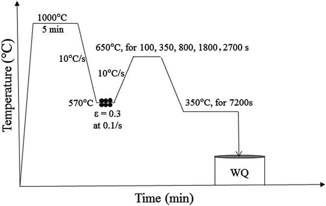
The samples were reheated to 1000 °C and held for 300 s (Fig. 1). The samples were then cooled to 570 °C and held for 10 s followed by deformation to a strain of 0.3 at a strain rate of 0.1 s−1. To study the effect of the ferrite volume fraction on the morphology of bainite and stability of the retained austenite, the deformed samples were reheated to 650 °C at 10 °C/s and held for 100, 350, 800, 1800, and 2700 s to partially transform the austenite to fine ferrite grains (i.e., from ∼2 to 4 μm on average depending on holding time), followed by cooling at 10 °C/s to 350 °C, where they were held for 7200 s to form low temperature bainite, followed by water quenching (Fig. 1).
Thermomechanical processing schedule. WQ is water quenching.

Four subsize tensile specimens with a gauge of 20 × 2 × 2 mm for each ferrite transformation time were machined by wire-cutting. The tensile axis was perpendicular to the deformation direction. Tensile testing was performed using an Instron 4500 Servohydraulic machine (Instron Pty. Ltd., Melbourne, Australia) with a crosshead displacement rate of 7.2 mm/min (i.e., corresponding to a nominal strain rate of 10−3 s−1).
The samples for optical characterization of the volume fraction of ferrite were cut parallel to the compression direction. The volume fraction of the polygonal ferrite was estimated in terms of the areal percent in optical micrographs, as the ratio of the areas of the total detected phase and the imaged regions. Eight to ten optical images were used to estimate the average value.
The thermomechanically processed samples for electron backscatter diffraction (EBSD) study were cut parallel to the compression direction and the microstructural examination (i.e., EBSD) was conducted in the central regions of the sample on a plane containing the compression axis. Samples for EBSD were prepared by standard mechanical polishing, and finished by a colloidal silica slurry polish. EBSD measurements were performed with a FEI Quanta 3D FEGSEM scanning electron microscope (SEM; FEI Company, Eindhoven, The Netherlands) operated at 20 keV and a spatial step size of 0.2 µm. The average confidence index of EBSD measurement was 0.69. Data acquisition and post processing were performed with the TexSEM Laboratories, Inc. software (TSL).
Different approaches were developed to separate the ferrite from martensite by EBSD and calculate the volume fraction of martensite.Reference Ryde[41–Reference Zaefferer, Romano and Friedel43] We employ the image quality approach as the diffraction pattern quality of martensite is lower than ferrite. Here, the image quality is averaged over each grain. The grains with good diffraction are considered ferrite and the grains with poor diffraction are defined as martensite.
Transmission electron microscopy (TEM) examination of thin foils was performed with a Philips CM-20 microscope operated at 200 keV. TEM samples were prepared with a solution containing 5% perchloric acid and 95% methanol at a temperature of −25 °C and a voltage of 50 V DC.
The volume fraction of retained austenite was measured by a Philips PW 1130 (40 keV, 25 mA) diffractometer. Spectra were taken in the range of 2θ from 30 to 120°. The integrated intensities of the (200)α, (211)α, (200)γ, and (220)γ peaks were used in the direct comparison methodReference Cullity[44] to calculate volume fraction of the retained austenite after different annealing times.
APT samples were cut perpendicular to the rolling direction and were polished according to the standard two-stage electro-polishing procedure.Reference Miller[45] Then, the APT samples were sharpened by annual milling in a FEI Nova 200 dual beam SEM/focused ion beam miller. APT experiments were performed at Oak Ridge National Laboratory with a CAMECA Instruments, Inc. (Madison, Wisconsin) local electrode atom probe (LEAP 4000X HR) operated in voltage pulsed mode with a specimen temperature of 60 K, a pulse repetition rate of 200 kHz, and a pulse fraction of 20%. Data analysis was performed with CAMECA Instruments Inc. IVAS 3.6.6 and PoSAP software.
III. RESULTS
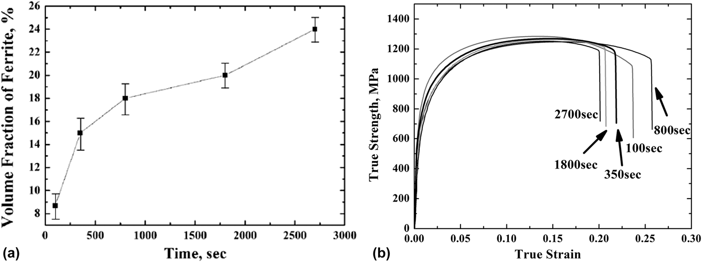
The thermomechanical processing approach used in this study is aimed to: (i) refine ferrite grains due to the low deformation temperature of 570 °C and the low ferrite transformation temperature of 650 °C, which reduces the mobility of grain boundaries, and limits coarsening of the ferrite, (ii) produce different volume fractions of ferrite and examine its effect on the bainite morphology, and (iii) form low temperature bainite consisting of fine layers of bainitic ferrite and retained austenite by reducing the B s and M s temperatures as a result of the high carbon content of the remaining austenite after ferrite formation.Reference Beladi, Kelly and Hodgson[2,Reference Timokhina, Pereloma and Hodgson36] It is well known that an optimum volume fraction of ductile ferrite is needed: (i) to maximize the amount of stable retained austenite and (ii) to contribute to the elongation and as a result (iii) to obtain a good strength–ductility balance.Reference Tsuzaki, Kodai and Maki[46,Reference Sandvik47] However, the ferrite volume fraction can affect the volume and morphology of bainitic ferrite that can indirectly influence the morphology of the retained austenite. Increasing the annealing time from 100 to 350, 800, 1800, and 2700 s at 650 °C was found to gradually increase the volume fraction of the ferrite from 9 ± 1 to 15 ± 1.5, 18 ± 1.5, 20 ± 1, and 23 ± 1%, respectively [Fig. 2(a)]. However, despite an increase in the volume fraction, the ultimate tensile strengths for the samples with different ferrite volume fraction were similar [Fig. 2(b)], whereas the total elongations varied in an unpredictable way [Figs. 2(b)], i.e., there is no direct correlation between the mechanical properties and volume fraction of ferrite. It was suggested that the reason for this behavior is the effect of ferrite volume fraction on the morphology of bainite and the stability of retained austenite that, in turn, affects the mechanical properties. To understand this effect, two extreme isothermal ferrite time conditions of 100 and 2700 s with almost similar ultimate tensile strengths but with total elongation of 23 ± 2 and 18 ± 1%, respectively, were chosen for microstructural study.
(a) Volume fraction of ferrite as a function of the isothermal time and (b) representative stress–strain curves of steel after different isothermal ferrite transformation times.
A. Microstructure after a 100 s of isothermal ferrite time at 650 °C
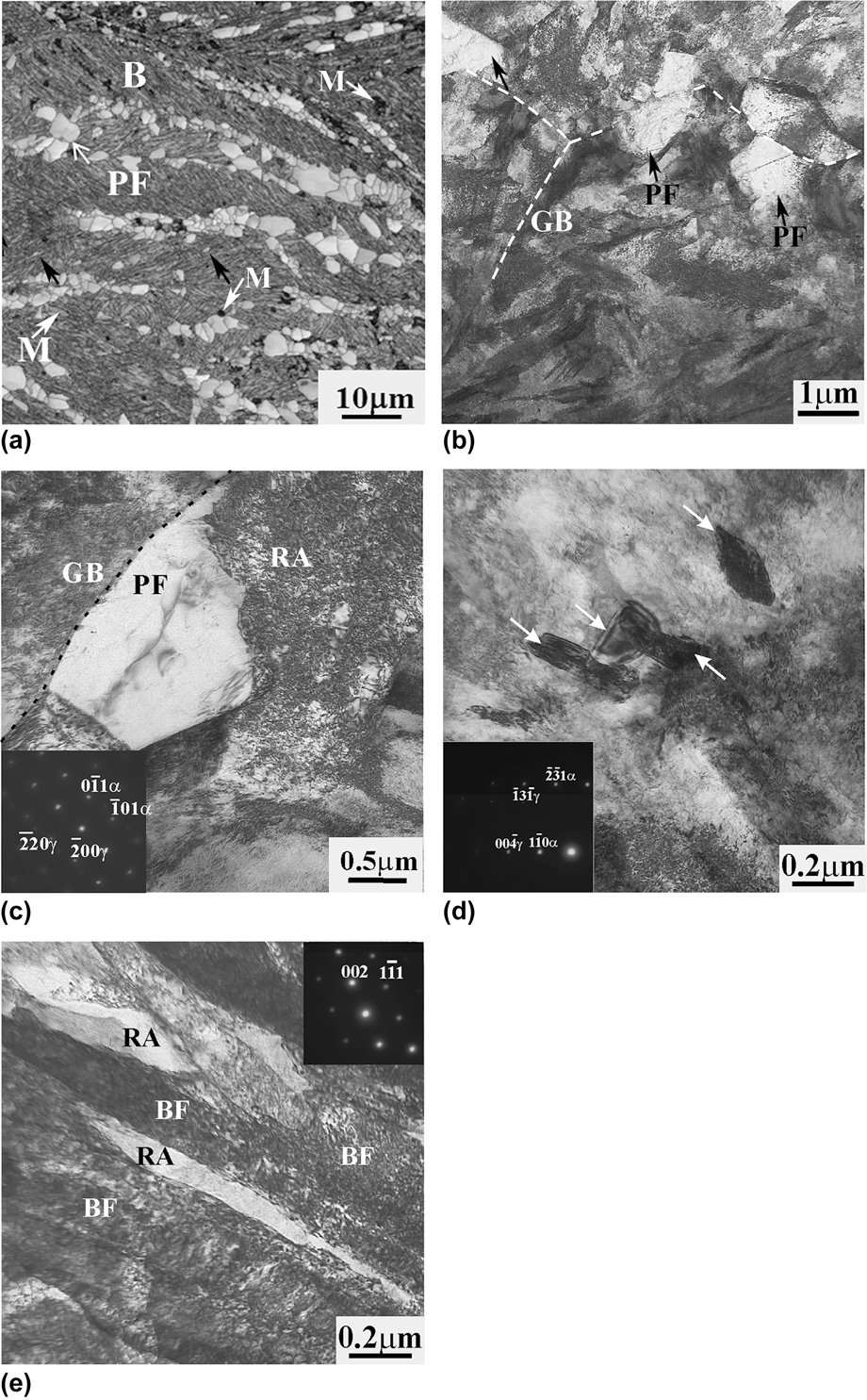
The microstructure of the samples after 100 s isothermal transformation consisted of fine ferrite grains formed along the prior austenite grain boundaries, UFF grains that were nucleated in the interior of retained austenite, as indicated by the black arrows in Fig. 3(a), low temperature bainite and martensite as indicated by the white arrows in Fig. 3(a). The fine ferrite grains that formed along the prior austenite grain boundaries were slightly elongated and had an average grain size of 2.3 ± 0.06 μm [Figs. 3(b) and 3(c)]. The intriguing microscopic feature found after the 100 s isothermal hold was the presence of intragranular UFF grains surrounded by bainite [Fig. 3(d)]. These grains showed a medium level (5–15°) of grain boundary misorientation with the matrix, and a diameter of 0.1 ± 0.04 μm [Fig. 3(d)]. It was believed that the nuclei of these grains were formed during the isothermal ferrite hold at 650 °C on intragranular defects, such as deformation bands, formed in the remaining austenite as a result of the warm deformation.
Microstructure formed in the samples after the 100 s isothermal hold: (a) SEM. EBSD image showing the distribution of phases, black arrows show the intragranular ferrite and white arrows point martensite, (b) TEM image of general view of UFF shown by black arrows and bainite, (c) an UFF grain near retained austenite and bainite (zone axis [111]α and [001]γ), (d) intragranular UFF grains pointed by white arrows (zone axis is [115]α), nucleated within the retained austenite layer with zone axis of [310]γ, and (e) bainite consisting of bainitic ferrite and retained austenite layers, zone axis of RA is [110]γ. M is martensite, RA is retained austenite, GB is grain boundary, B is bainite, BF is bainitic ferrite and PF is polygonal ferrite. The dashed lines represent the positions of prior austenite grain boundaries.
The x-ray analysis confirmed the presence of 11 ± 1% retained austenite, the volume fraction of martensite analyzed by X-ray diffraction (XRD) and EBSD was 4 ± 2% of martensite. The retained austenite was present as layers in bainite [Fig. 3(e)] and blocky-shaped features near ferrite grains [Fig. 3(c)]. Bainite consisted of fine layers of bainitic ferrite with an average thickness of 0.2 ± 0.05 μm, and fine layers of the retained austenite with an average thickness of 0.1 ± 0.02 μm [Fig. 3(e)]. The difference in the retained austenite morphology could be associated with the difference in carbon content of the remaining austenite after ferrite transformation, i.e., the remaining austenite near freshly formed ferrite grains before the bainite transformation has higher carbon content, and instead of transforming to bainite, remain in the microstructure after processing in the form of blocks due to the reduced B s and M s temperatures.
B. Microstructure after a 2700 s of isothermal ferrite time at 650 °C
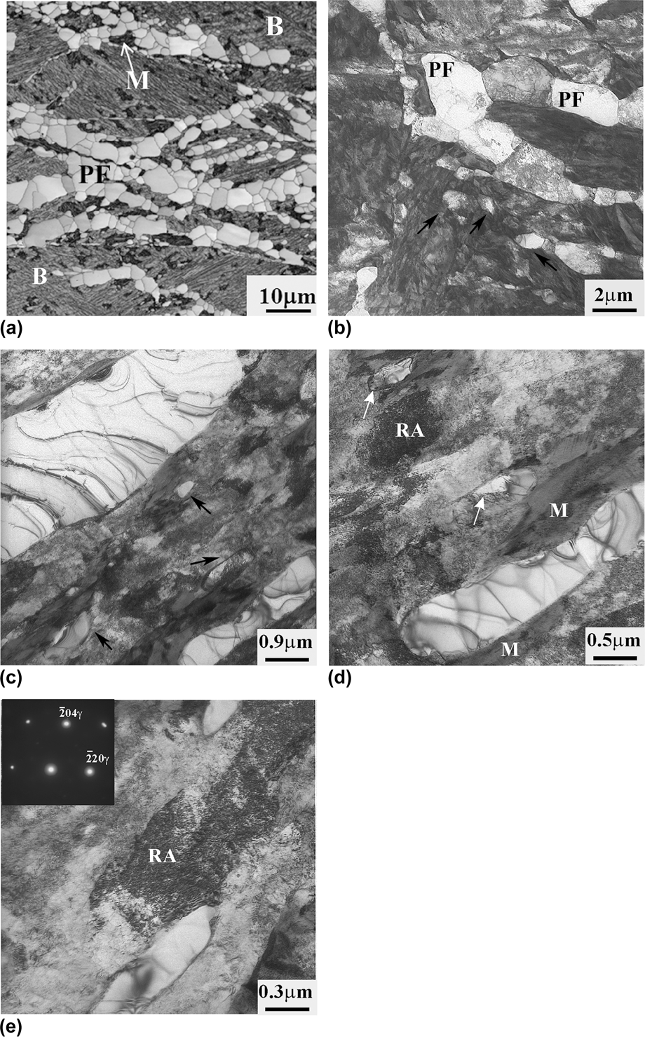
Increasing the ferrite isothermal transformation time to 2700 s after warm deformation led to an increase in the volume fraction of ferrite, with the formation of two types of the ferrite grains: (i) grains formed along the prior austenite grain boundary, and (ii) grains formed intragranularly in the austenite grain interior [Figs. 4(a) and 4(b)].
(a) SEM. EBSD and (b–e) TEM images of the microstructure formed after the 2700 s hold showing: (a) the distribution of phases, (b) general view, black arrows point the intragranular ferrite grains, (c–e) the redistribution of the phases in microstructure, white arrows show the intragranular ferrite. The zone axis for (e) (inset) is [221]γ. M is martensite, RA is retained austenite, B is bainite, PF is polygonal ferrite.
This longer time led to an increase in the volume fraction of intragranular ferrite, as the nucleation sites at the prior austenite grain boundaries were occupied by the ferrite grains early in the transformation, as could be seen from the sample aged 100 s. Hence, the grain boundary ferrite only coarsened for the majority of the isothermal ferrite time, whereas the intragranular ferrite underwent both nucleation and growth. The ferrite grains along the grain boundary had an equiaxed shape with a grain size from 4 to 8 μm [Fig. 4(b)]. The intragranular ferrite grains were in-homogenously distributed within the bainite and had a thickness between 0.1 and 0.8 μm [Figs. 4(a) and 4(c)]. It appeared that the intragranular grains were elongated along deformation bands in the austenite. The intragranular ferrite grains exhibited different levels of development, i.e., different sizes, dislocation densities, and grain boundary misorientations with the matrix [Fig. 4(c)]. More developed grains were coarser (∼0.8 μm), had a low dislocation density, and high a degree of grain boundary misorientation with the matrix, whereas, the finer grains (∼0.1 μm) had a higher dislocation density, and lower boundary misorientation with the matrix [Fig. 4(d)].
The volume fraction of the retained austenite after the 2700 s hold increased to 15 ± 1%. Moreover, based on the EBSD, x-ray, and TEM analysis, a relatively high ∼10 ± 1% amount of martensite was present in the microstructure after processing.
It appeared that the formation of intragranular ferrite grains prior to the bainite transformation, as well as their size and positions, affects the nature of the surrounding phase. After the 100 s hold, the retained austenite and martensite blocks were, in most cases, near the ferrite grains formed along prior austenite grain boundaries. After 2700 s, the blocky martensite or retained austenite was observed near the intragranularly formed ferrite rather than near the ferrite formed along the grain boundaries [Figs. 4(a), 4(d), and 4(e)]. The carbon content of the remaining austenite before quenching controls whether the block transforms to the martensite or remains as austenite.
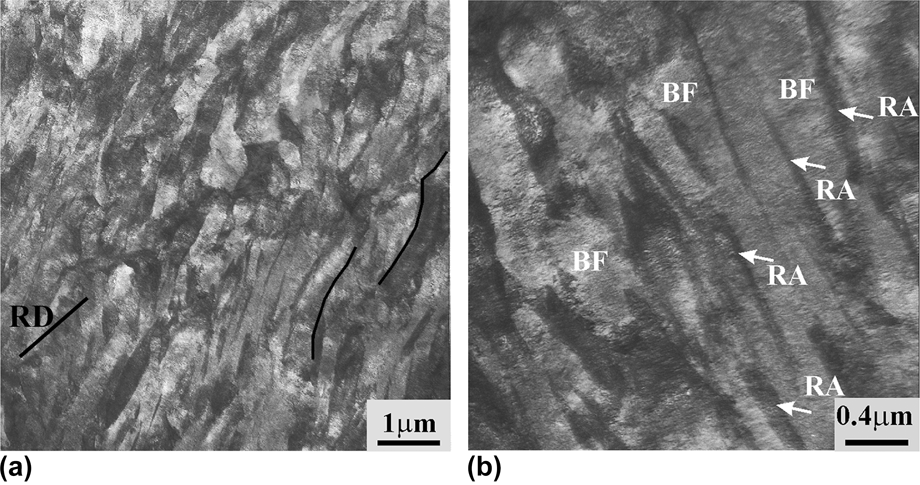
The dominant bainite morphology, in the areas far from intragranular ferrite grains, was bainite consisting of bainitic ferrite with a thickness from 0.2 to 0.3 μm and retained austenite with a thickness of 60 ± 10 nm (Fig. 5). It appeared that the preferential orientation of the bainitic ferrite layers was along the intragranular deformation bands formed after warm deformation, because the bainitic ferrite layers were aligned along a similar direction. This is consistent with the recent work showing the preferential nucleation of bainitic ferrite laths along the active slip planes.Reference Calcagnotto, Pongo and Raabe[31,Reference Beladi, Timokhina, Xiong and Hodgson32] The deformation limits the number of bainitic variants formed in a given austenite grain (i.e., strong variant selection).Reference Malet, Barnett, Jacques and Godet[48,Reference Gong, Tomota, Koo and Adachi49]
TEM micrographs of bainite formed after 2700 s hold: (a) lower and (b) higher magnification. BF is bainitic ferrite, RA is retained austenite, RD is rolling direction.
C. APT study after 100 and 2700 s of isothermal ferrite time at 650 °C
APT was used to study the carbon redistribution between the phases, i.e., ferrite, bainitic ferrite, and martensite/retained austenite of the samples after the 100 and 2700 s isothermal hold. As shown in the representative carbon atom map [Fig. 6(a)], there are two distinct regions with higher and lower carbon content representing the martensite/retained austenite and ferrite regions, respectively, observed for both isothermal ferrite times. It should be noted that it is probable that all retained austenite regions in the microstructure were transformed to martensite during the cooling to the analysis temperature of 60 K in the LEAP, i.e., it was not possible to make a distinction between the martensite formed as a result of quenching during thermomechanical processing and that formed through operation of the LEAP. Compositional analysis of several C atom maps (3 atom maps from ferrite, 4 atom maps from martensite/retained austenite, and bainitic ferrite for each intercritical annealing times) allowed an estimation of the average C content of ferrite, 0.08 ± 0.04 at.%, bainitic ferrite 0.4 ± 0.08 at.%, and martensite/retained austenite of 3.8 ± 0.7 and 6.5 ± 0.2 at.%. It should be highlighted here that the phase compositions after both isothermal ferrite treatments were similar. The carbon content analysis was performed on the areas far from any local concentration variations, such as interface segregation, particles, etc. It is also possible to estimate the size of the retained austenite/martensite regions from APT data. It appeared that the retained austenite/martensite with lower 3.8 ± 0.7 at.% of carbon content represented the blocky retained austenite/martensite [Fig. 6(a)], as their size exceeded the size of layer-type of retained austenite/martensite (60 ± 10 nm), as estimated by TEM. The retained austenite/martensite with a higher carbon content of 6.5 ± 0.2 at.% C seemed to represent the layer-type, as its size was equivalent to 60 ± 10 nm [Fig. 6(b)]. The average Mn content of ferrite and martensite/retained austenite was estimated to be 1.67 ± 0.03 and 2.6 ± 0.2 at.% Mn, respectively, whereas the average Mo level in ferrite and martensite/retained austenite was 0.15 ± 0.02 and 0.25 ± 0.05 at.%, respectively.
(a) Representative C atom map of ferrite and blocky retained austenite/martensite, (b) C atom map of bainitic ferrite and a layer of retained austenite/martensite, (c) Mn and (d) Mo atom maps and (e) corresponding C, Mn, and (f) Mo proximity histograms across the interface of ferrite and blocky retained austenite/martensite; (a–d) isosurface (1 at.%) of interface, isolated isosurface fragments have been removed for clarity. RA is retained austenite, M is martensite, F is ferrite, and UF is ultrafine ferrite. Dashed lines in (e and f) represent the interface between retained austenite/martensite and ferrite.
APT also enabled the distribution of the alloying elements across the ferrite and retained austenite/martensite interface to be evaluated. The atom maps and the proximity histogram across the ferrite, and retained austenite/martensite interface were used to study chemical gradients across interface. The position of the interface between ferrite and retained austenite/martensite was defined based on the concentration of main elements such as C and Mn in ferrite and austenite. The interface was positioned at the midpoint of the concentration difference in C and Mn between austenite and ferrite. APT on the samples after 100 s of isothermal ferrite time did not show any chemical gradients across the interface, while the interface study after 2700 s revealed the chemical changes across the ferrite and retained austenite/martensite interface. The C atom map and the proximity histogram across the ferrite, and retained austenite/martensite interface revealed a small carbon concentration peak from an average of 4.5 to 5.2 at.% C, at ∼0.75 nm from the ferrite and retained austenite/martensite interface on retained austenite/martensite site [Figs. 6(a) and 6(e)]. Analysis of the Mn atom map and the proximity histogram across the ferrite and retained austenite/martensite interface also showed intriguing Mn behavior, i.e., a decrease in Mn concentration in ferrite from an average of 1.5 to 0.9 at.% near the ferrite and retained austenite/martensite interface followed by the build-up of a Mn spike from an average of 2.2 to 3.8 at.% at ∼0.75 nm from the interface within the martensite/retained austenite [Figs. 6(c) and 6(e)], i.e., at the distance similar to where the increase in carbon content was observed. Moreover, a small Mo concentration peak was also observed at ∼0.5 nm from the ferrite and retained austenite/martensite interface as for C and Mn [Figs. 6(d) and 6(f)]. In addition, the analysis of the bainitic ferrite and retained austenite/martensite interfaces did not show any chemical gradients across interface.
IV. DISCUSSION
A. Effect of ferrite volume fraction on bainite and retained austenite
As mentioned above, two types of ferrite grains were formed after thermomechanical processing schedules with both isothermal times of 100 and 2700 s: (i) ferrite grains along prior austenite grain boundaries, and (ii) intragranular ferrite grains. The refinement of both types of ferrite grains was due to the low deformation temperature of 570 °C and low ferrite isothermal transformation holding temperature of 650 °C. The former promotes more ferrite nucleation sites at a given condition compared with the conventional deformation temperatures (i.e., 950–800 °C), enhancing the impingement of ferrite grains at an early stage of ferrite formation. The latter retards the coarsening of ferrite grains, as the coalescence of grains remarkably reduces with a decrease in the temperature. It was suggested in the current study that the elongation of the samples after 100 s of isothermal ferrite time will be improved due to the formation of ductile ferrite along the prior austenite grain boundary as well as retained austenite stabilization, whereas the total elongation of 2700 s samples will be enhanced not only by the formation of grain boundary ferrite but also due to the intragranular ferrite formation which can further stabilize the remaining austenite inside the grain. However, the mechanical property behavior was different than the suggested behavior [Fig. 2(b)]. The main motivation was to understand the relationship between the microstructure and mechanical properties of studied steel.
The nucleation and growth of ferrite during the 100 s hold occurred preferentially along the prior austenite grains, followed by the nucleation and subsequent growth of ferrite grains at the intragranular defects during further annealing for 2700 s, then the fine bainite consisting of bainitic ferrite and retained austenite layers was formed around intragranular ferrite. The intragranular ferrite grains were in-homogeneously distributed within the prior austenite grain interior and had different grain sizes from 0.1 to 0.8 μm. An increase in the volume fraction of ferrite grains with an increase in isothermal ferrite time enhanced the volume fraction of the retained austenite and martensite. This effect was predicted because the growth of ferrite is accompanied by the rejection of carbon into untransformed austenite, which thereby decreases the martensite transformation temperature (M s) and increases the volume fraction of the retained austenite. However, as mentioned above, the preferential nucleation and growth of ferrite grains after isothermal hold for 100 s occurred at the intragranular defects inside the prior austenite grains. This led to reinforcement of an in-homogeneous carbon redistribution within the remaining austenite after ferrite transformation, and to an increase in the volume fraction of the blocky retained austenite/martensite, and to a decrease in volume fraction of bainite after annealing for 2700 s. The main disadvantage of this microstructure was that blocky retained austenite is less stable to deformation, and tends to transform to martensite at low strain.Reference Timokhina, Pereloma and Hodgson[36] The TEM observation confirmed that the blocky retained austenite/martensite was located near ferrite grains, whereas the layer shaped was enclosed by bainite formed far from ferrite grains. Based on APT, it was found that the blocky retained austenite/martensite has a lower carbon content than the layer shaped retained austenite/martensite due to the second carbon enrichment during the bainite transformation and layer morphology of the retained austenite. This confirms the lower chemical stability of blocky retained austenite compared to the layered form. Hence, despite the volume fraction of the retained austenite increasing after 2700 s compared to 100 s, the amount of the stable retained austenite layers decreased and, as a result, the mechanical properties deteriorated.
It was also expected that the formation of intragranular ferrite could possibly accelerate the bainite transformation, as the austenite/ferrite interface formed during intragranular ferrite formation might be a favorable nucleation site for bainite lath nucleation.Reference Quidort and Brechet[50] However, TEM observation did not find any evidence of nucleation of bainitic ferrite layers at the intragranular ferrite.
It could be concluded that there is an optimum amount of ferrite in the TRIP microstructure to achieve the appropriate mechanical property balance.
B. APT analysis of solutes redistribution across the austenite/ferrite interphase after 2700 s of isothermal ferrite time
As was mentioned above, Mn addition is beneficial for the grain refinement since Mn reduces the grain boundary mobility.Reference Calcagnotto, Pongo and Raabe[31] The atom maps and the proximity histogram obtained from both the ferrite and martensite phases after 100 and 2700 s of isothermal ferrite time revealed that there is no chemical gradients of solute atoms across the ferrite and retained austenite/martensite interface after 100 s of isothermal time, whereas the solute redistribution across the ferrite and retained austenite/martensite interface after 2700 s at 650 °C showed segregation of C, Mn, and Mo in the austenite within a distance of ∼0.5–0.75 nm from the ferrite and retained austenite/martensite interface that could control the ferrite grain size.
As mentioned above, Mn is an austenite stabilizer,Reference Hashimoto, Sudo, Mimura and Hosoda[51] has a low diffusion rate in austenite,Reference Gilmour, Purdy and Kirdalky[52] and changes the kinetics of ferrite growth by segregation to the ferrite and retained austenite/martensite interface.Reference Hashimoto, Sudo, Mimura and Hosoda[51–Reference Bradley and Aaronson54] The presence of Si (3.8 at.%) in the steel further enhances the tendency for Mn segregation to the austenite boundary.Reference Wada, Wada, Elliott and Chipman[53,Reference Bradley and Aaronson54] Therefore, the depletion of ferrite and enrichment of austenite in Mn as shown in Fig. 6(d) were expected. The segregation of Mn and the formation of a Mn spike from an average value of 2.2 to a peak value of 3.8 at.% within ∼0.75 nm of the ferrite and retained austenite/martensite interface after 2700 s was suggested to be due to: (i) segregation of Mn to the interface during the austenite-to-ferrite transformation at the low isothermal transformation holding temperature of 650 °C for a long isothermal time, and/or (ii) further redistribution of Mn over distances larger than interfacial region, which involves diffusion of Mn at the bainite transformation temperature of 350 °C.
The accumulation of Mn at the ferrite and retained austenite/martensite interface followed by Mn partitioning during the austenite-to-ferrite transformation, which retards growth of ferrite grain in Fe–C–Mn–Si steels, has been discussed by different groups.Reference Bradley and Aaronson[54–Reference Guo, Purdy, Enomoto and Aaronson56] The interaction of Mn with the moving ferrite and retained austenite/martensite interface and the slowing down of the transformation of austenite to ferrite have been explained by the solute drag effect and by the kinetic transition from paraequilibrium (PE) to local equilibrium negligible partition (LENT) condition at the ferrite and retained austenite/martensite interface.Reference Capdevila, Cornide, Tanaka, Nakanishi and Urones-Garrote[55,Reference Guo, Purdy, Enomoto and Aaronson56] The transition was assumed to occur when the velocity of moving ferrite and retained austenite/martensite interface is slow enough to be comparable with the Mn diffusivity, which leads to the build-up of a Mn spike at the interface.Reference Bradley and Aaronson[54–Reference Guo, Purdy, Enomoto and Aaronson56] The kinetic transition depends on the transformation temperature and transformation time.Reference Capdevila, Cornide, Tanaka, Nakanishi and Urones-Garrote[55] It has been reported that the LENT condition was operated at lower transformation temperatures, when the PE condition occurred at higher, i.e., above the transformation temperature of 825 °C.Reference Bradley and Aaronson[54–Reference Zurob, Hutchinson, Béhé, Purdy and Bréchet57] It should be emphasized that the Mn spike was observed within ∼0.75 nm of the interface, not exactly at the interface. The Mn segregation at the ferrite and retained austenite/martensite interface and a Mn pile up in front of the interface on austenite side in the Fe–C–Mn–Si alloy at low (656 °C) transformation temperature has been discussed by other researchers.Reference Thuillier, Danoix, Gounbé and Blavette[58] In more detail, the difference in chemical potentials of Mn and Fe is assumed to cause an unbalanced flux of Mn to flow across the interface, which, in turn, builds up a concentration spike. It was also considered that the width of the Mn spike increases faster when the velocity of the interface becomes lower compared to the Mn diffusivity (at low transformation temperatures), i.e., cross-interfacial jumps become more efficient. Hence, it could be suggested that the formation of the Mn spike occurred during the austenite-to-ferrite transformation at 650 °C for 2700 s. However, as the thermomechanical processing included the formation of bainite at 350 °C for 7200 s, pipe diffusion of Mn in austenite, due to its high dislocation density near the interface during the bainite transformation, could also be proposed. It appears for this study that due to the low transformation temperature, the LENT mode of the interfacial condition occurred, and caused the formation of the Mn spike in front of the interface. Similar results have been recently observed by Ref. [Reference Seol, Raabe, Choi, Im and Park38]. It was suggestedReference Seol, Raabe, Choi, Im and Park[38] that the accumulation of Mn at the interface or near the interface can lead to a solute drag effect, which could exceed the driving force for the austenite-to-ferrite transformation so the transformation could be kinetically blocked.
A small increase of ∼0.8 at.% in carbon content within 0.75 nm of the interface, i.e., within similar distance as the Mn spike, was also observed [Figs. 6(a) and 6(d)]. The growth of ferrite is accompanied by the rejection of carbon into untransformed austenite during the austenite-to-ferrite transformation. However, the formation of a C spike in front of the interface on austenite side was suggested to be due to the diffusion of C out of the ferrite–austenite interface during the subsequent bainite formation at 350 °C. In contrast, there has been no observation of build-up of carbon concentration spike at the ferrite and retained austenite/martensite interface in the recent study by othersReference Seol, Raabe, Choi, Im and Park[38] owing to the fact that carbon diffuses much faster inside the austenite than the substitutional atoms do, despite its strong affinity to Mn.
The formation of a small spike of Mo near the ferrite and retained austenite/martensite interface was shown by APT [Figs. 6(e) and 6(c)]. It is more likely that accumulation of Mo occurred during the austenite-to-ferrite transformation. Mo is a ferrite former, but retards the kinetics of ferrite transformation and lowers the bainite start transformation temperatures.Reference Guo, Yang, Shang, Wang and He[59] Mo also has a strong solute drag effect and increases the hardenability of steel.Reference Akben, Bacroix and Jonas[23,Reference Wada, Wada, Elliot and Chipman24,Reference Bouet, Fillipine, Essadiqi, Root and Yue60] It has been found for steel with Mo and transformation temperatures of 630–650 °C (Ref. [Reference Humphreys, Fletcher, Hutchins, Garratt-Reed, Reynolds, Aaronson, Purdy and Smith61]) that Mo tends to diffuse from the ferrite to austenite, where, because of the lower diffusion, it builds up in a “spike” in the austenite near the ferrite and retained austenite/martensite interface. The diffusional distance of Mo in austenite at 630 °C for 1000 s was calculated to be 1.4 nm.Reference Fridberg, Torndahl and Hillert[62] So, accumulation of Mo in austenite near the ferrite and retained austenite/martensite boundary is possible at the transformation temperature of 650 °C and a transformation time of 2700 s. Moreover, it appeared that the low overall concentration of Mo (0.35 at.%) is needed near the interface to produce the strong retardation of transformation kinetics, as observed in previous research.Reference Fridberg, Torndahl and Hillert[62]
V. CONCLUSIONS
The development of a novel thermomechanical processing route led to the formation of fine ferrite due to the warm deformation at 570 °C and low transformation temperature of 650 °C and fine bainite at the temperature of 350 °C. Moreover, it was suggested that the ferrite grain size and ferrite transformation could be affected by the segregation of Mn and Mo near the ferrite and retained austenite/martensite interface during transformation at low temperature. The effect of different volume fractions of ferrite on the formation of fine bainite and stable retained austenite was also investigated. It was found that:
(1) An increase in volume fraction of ferrite did not lead to an increase in elongation due to the preferential formation of retained austenite with low stability, such as blocky retained austenite.
(2) An increase in volume fraction of ferrite decreased the volume fraction of fine bainite with stable layers of retained austenite.
ACKNOWLEDGMENTS
The authors would like to acknowledge the technical and scientific support of the Center for Electron Microscopy at Monash University. One of the authors (I.T.) acknowledges the support of Outside Study Program from Deakin University. One of the authors (P.D.H.) also acknowledges the support of the ARC Laureate Fellowship scheme. Atom probe tomography (M.K.M.) was supported through a user project supported by ORNL's Center for Nanophase Materials Sciences (CNMS), which is sponsored by the Scientific User Facilities Division, Office of Basic Energy Sciences, U.S. Department of Energy.