1. INTRODUCTION
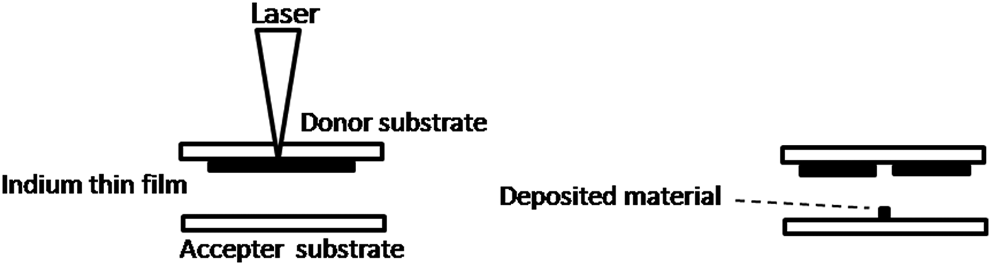
Nanosecond and femtosecond lasers have been extensively used in recent years for machining and laser-writing of thin films of different kinds. The use of lasers is now beginning to also find utility in controlled, micron-sized deposition of materials on to substrates, with applications spanning diverse fields like micro-electronics, opto-electronics, semiconductor industries, and biomedical research. Laser-induced forward transfer (LIFT) is one such micro-deposition technique that has recently evolved; it facilitates transfer of particles from thin films to other proximate surfaces by focusing nanosecond or femtosecond laser pulses from the rear side of a thin film that is deposited onto a transparent substrate (see Fig. 1 for a schematic depiction of a typical experimental configuration). LIFT was first reported by Bohandy et al. (Reference Bohandy, Kim and Adrian1986) for patterned copper deposition. Depending on the laser-thin film interaction, micron- or nano-sized material are ejected from the irradiated thin film and are deposited onto another substrate that is located sufficiently close to it. LIFT technique has been applied on variety of materials. For example, it have been used for transferring radioactive contaminants (Veiko et al., Reference Veiko, Shakhno, Smirnov, Miaskovski and Nikishin2006), laser dyes (Nakata et al., Reference Nakata, Okada and Maeda2002), superconducting materials (Fogarassy et al., Reference Fogarassy, Fuchs, Kerherve, Hauchecome and Perriere1989), DNA (Colina et al., Reference Colina, Serra, Fernández-Pradas, Sevilla and Morenza2005), microarrays of DNA (Seera et al., Reference Seera, Colina, Fernández-Pradas, Sevilla and Morenza2004), Trichoderma longibrachiatum conidia (Hopp et al., Reference Hopp, Smausz, Barna, Vass, Antal, Kredics and Chrisey2005), thermally and mechanically sensitive materials (Kattamis et al., Reference Kattamis, Purnick, Weiss and Arnold2007) and thin films of various metals for example gold (Nakata & Okada, Reference Nakata and Okada1999) indium (Alti, Reference Alti, Patra, Khare and Maximilian2008) aluminum using femtosecond (fs) laser (Bera et al., Reference Bera, Sabbah, Yarbrough, Allen, Winters, Durfee and Squier2007), and aluminum zinc and chromium using temporally shaped fs pulses (Klini et al., Reference Klini, Loukakos, Gray, Manousaki and Fotaki2008).
Schematic diagram of the LIFT (laser induced forward transfer) technique.

LIFT offers some unique advantages over other techniques. First, there is no chemical reaction involved in the LIFT process: the technique is, as a consequence, a “green” technique in that it permits retention of the purity of deposited microelectronic materials. Second, LIFT can be implemented under ambient atmospheric conditions. As already noted, LIFT has been demonstrated using both nanosecond and femtosecond lasers; use of femtosecond lasers seems to allow greater precision of energy deposition compared to that obtained with nanosecond pulses. Tolbert et al. (Reference Tolbert, I-Yin, Xiaoning, Dlott, Doxtader and Ellis1993) first demonstrated that the pulse duration has an effect on the transfer process. Although, instead of femtosecond laser authors used picoseconds laser to show the increase in efficiency as compared to nanosecond laser. Due to melting effects with nanosecond lasers (Adrian et al., Reference Adrian, Bohandy, Kim and Jette1987; Schultze et al., Reference Schultze and Wagner1991), fabrication of high quality patterns is difficult. Advantage of using femtosecond laser over the nanosecond laser for micro-machining applications is studied previously (Chichkov et al., Reference Chichkov, Momma, Nolte, Alvensleben and Tunnermann1996). Recently, Banks et al. (Reference Banks2008) has done detailed comparative study of nanosecond and femtosecond laser based LIFT technique and its possible mechanisms.
The physical mechanism governing LIFT of solid thin films is expected to depend on laser intensity. Intensity-wise there appear to be four distinct LIFT regimes (details of which have been cogently reviewed by Veiko et al., Reference Veiko, Shakhno, Smirnov, Miaskovski and Nikishin2006). The amount of optical energy that is deposited into the substrate determines whether ablated particles comprise film fragments, vapor, atoms, or ions. In the low intensity regime, solid or molten film fragments are transferred to the accepter surface. At higher intensity levels, the thin film evaporates and condenses at the accepter substrate. Further enhancement of laser intensity creates a regime in which laser-induced ions and excited atoms are implanted into the substrate. There are two types of velocity components of particles that exit the donor substrate: — slow and fast — moving with velocities of the order of about 100 m/s and few km/s, respectively. The magnitude of the ejected material's velocity appears to depend on experimental conditions such as target material (thickness of the thin film, adhesion and other physico-chemical properties of the material), the incident laser intensity, atmospheric conditions, and the ablation geometry.
Proper insights into the physics that underlies the LIFT process remain to be obtained. It appears likely that the technique relies on absorption by the irradiated material of optical energy from the laser beam. This gives rise to localized heating, causing vaporization and subsequent expulsion of material from the donor substrate. In the case of non-absorbing substrates, appropriate doping is sometimes carried out so as to enable proxy heating of the substrate. Within this scenario of incomplete understanding of basic physics issues accompanied by a plethora of potential applications, it is clearly of interest to carry out systematic studies of experimental parameters so as to gain better insights into the parameter spaces required for LIFT to be efficiently utilized.
We report here the results of LIFT experiments that we have conducted to re-deposit indium thin films onto an accepter substrate using nJ energy laser pulses from a femtosecond laser oscillator. We particularly wished to develop methods of re-depositing indium on to accepter substrate in form of lines and dots by controlling the motion of the accepter substrate relative to the donor substrate. Effects of laser pulse energy and the relative motion between accepted and donor substrate on the LIFT pattern are discussed in the following. We discover that either dots, or straight lines, or comet-like shapes can be generated on the acceptor substrate, depending on the relative motion of the two substrates. This relative motion also determines the thickness and overall density of the deposited lines.
2. EXPERIMENTAL SET-UP
A high-energy Ti:Sapphire femtosecond laser oscillator (800 nm wavelength, 200 nJ energy, 50 fs pulse duration, and 5.2 MHz repetition rate) was used for LIFT (Fig. 2). We used a single-shot autocorrelator to monitor, on-line in the course of the experiments, the pulse width of the laser. The laser pulse energy was attenuated with the help of a half wave plate and polarizer assembly. The laser beam was transported using appropriate optics so that it could be focused on the rear side of the donor indium thin film, with the final focusing being carried out with a 10× (NA 0.25) microscopic objective. The focal spot size of the microscopic objective was measured by us using a beam profiler to be 2.7 µm in the course of our measurements. The transmission of the microscope objective was measured using integrating sphere to be about 93%.
(Color online) Schematic diagram of the experimental set-up used for transferring indium thin films onto donor substrates.
The donor thin film was mounted on a three-dimensional motorized translation stage while the accepter substrate was kept on a one-dimesional motorized translation stage. In one series of experiments, we kept the accepter substrate in stationary position while in other instances we moved the accepter substrate at the same speed as the donor substrate. The sample was initially scanned several times to approximately optimize the focal position on the donor thin film. Systematic studies were carried out by varying the laser pulse energy over the range 19 nJ to 93 nJ and varying the translation speed of the donor substrate from 1 mm/s to 10 mm/s. Typically, the distance between accepter and donor thin films was kept within 400 µm. This distance is way beyond the Rayleigh length (about 29 µm). Considering the highest pulse energy used in this work, i.e., about 100 nJ, laser fluence intensity was calculated to be 1.7 J/cm2 for the focal spot size of 2.7 µm. However, in the real experiment, donor substrate was kept approximately at the focal length within ± 20 µm. Considering this, laser fluence further reduces to 1.19 J/cm2 for the focal spot size of 3.3 µm. At 400 µm, spot size expands to 37 µm and intensity decreases to 0.0093 J/cm2 which is very low for the re-ablation of the material from accepter substrate. Previous studies by Hafez and Elsayed-Ali (Reference Hafez and Elsayed-Ali2006) utilized low laser fluencies of 0.4–0.6 J/cm2 for the pulsed laser deposition of Indium using femtosecond laser (130 fs, 1–2 Hz repetition rate).
Donor indium thin films were deposited on cleaned microscopic glass plates (size 2.5 × 7.5 cm) via a thermal evaporation coating unit kept at a base pressure of 10−6 Torr. The indium that we used for deposition was of purity 99.995% (Nuclear Fuel Complex, Hyderabad). Typical thicknesses of these thin films were in between one to two microns. Donor substrates and LIFT patterns on acceptor substrates were studied using optical microscopy, scanning electron microscopy (SEM), and energy-dispersive X-ray diffraction (EDAX).
3. RESULTS AND DISCUSSION
In case of LIFT that we implement using a femtosecond laser oscillator (with laser pulse energies of the order of few nJ, at MHz repetition rate), localized melting and subsequent evaporation/ejection is the most likely scenario for the re-deposition of thin films on to accepter substrates. Considering the repetition rate of 5.2 MHz, donor translation speed of 1 mm/s and 2.7 µm focal spot sizes, ideally 14 × 103 pulses overlap spatially. For the higher speeds, number of overlap pulses will decrease. Therefore, with such laser, multiple pulses are responsible for the ejection of the material from the donor substrate. To calculate the rough estimate of the minimum number of laser pulses required for the complete removal of the film having maximum thickness of 2 µm, we consider the minimum laser pulse energy, i.e., 19 nJ and maximum speed of the donor substrate, i.e., 10 mm/s, used in this work. Temporal gap between the successive laser pulses is taken to be about 10−6 s. With 10 mm/s speed, donor substrate is going to move by 10 nm in 10−6 s. Now if the focal spot size is taken to be about 3 µm (1.5 µm radius), number of pulses which have spatial overlap of 50% or greater than 50% is found to be 150. For 19 nJ and about 3 µm spot size, laser fluence is 0.055 J/cm2. So for minimum laser pulse energy and maximum speed of the donor substrate used in this work, number of laser pulses required for the complete removal of the Indium film is found to be 150.
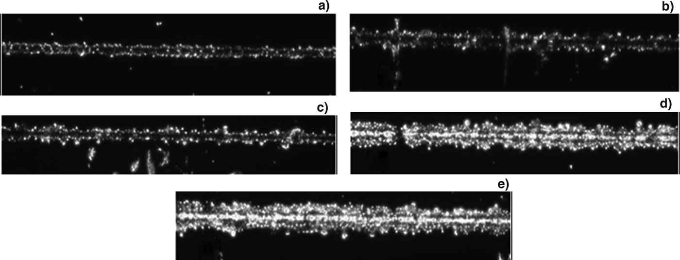
Figure 3 shows the laser energy dependence that we measured of regions of indium thin films were machined on donor substrates. The width of the machined region varies from 18 µm to 47 µm as the laser energy increases from 19 nJ to 93 nJ. For these cases, we kept the translation speed of the donor substrate constant at 1 mm/s.
Optical micrographs of laser-machined regions of indium thin films on donor substrates for various values of laser energy. The scanning speed was kept at 1 mm/s. (a) 19 nJ, (b) 37 nJ, (c) 56 nJ, (d) 74 nJ, and (e) 93 nJ.
From Figure 3, it is observed that as the laser energy increases, the width of the machined region also increases. One interesting observation is that, at higher energies, smaller grain-like structures are left behind on the donor substrate after machining compared to that at lower energies. This could be due to re-deposition of the ablated material back on to the donor substrate. As the microscope was used in the transmission geometry, absence of indium in the machined region is indicated by bright region.
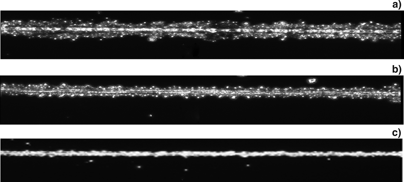
Figures 4a and 4b show optical micrographs of machined regions of indium thin film at donor translation speeds of 1 mm/s and 5 mm/s for the same laser pulse energy (93 nJ). It is seen that the width of the machined region decreases with increase in scanning speed of the donor substrate.
Optical micrographs of the machined regions of indium thin films on donor substrates. The laser pulse energy, translation speed and width of the machined region were (a) 93 nJ, 1 mm/s and about 49 µm, (b) 93 nJ, 5 mm/s and about 24 µm, and (c) 19 nJ, 10 mm/s and about 11 µm.
Figure 4c shows a machined width of 11 µm for 19 nJ laser pulse energy and 10 mm/s donor substrate speed. It is clear from Figure 4 that comparatively smooth and narrow machined regions are produced when the donor film is scanned at relatively high speed.
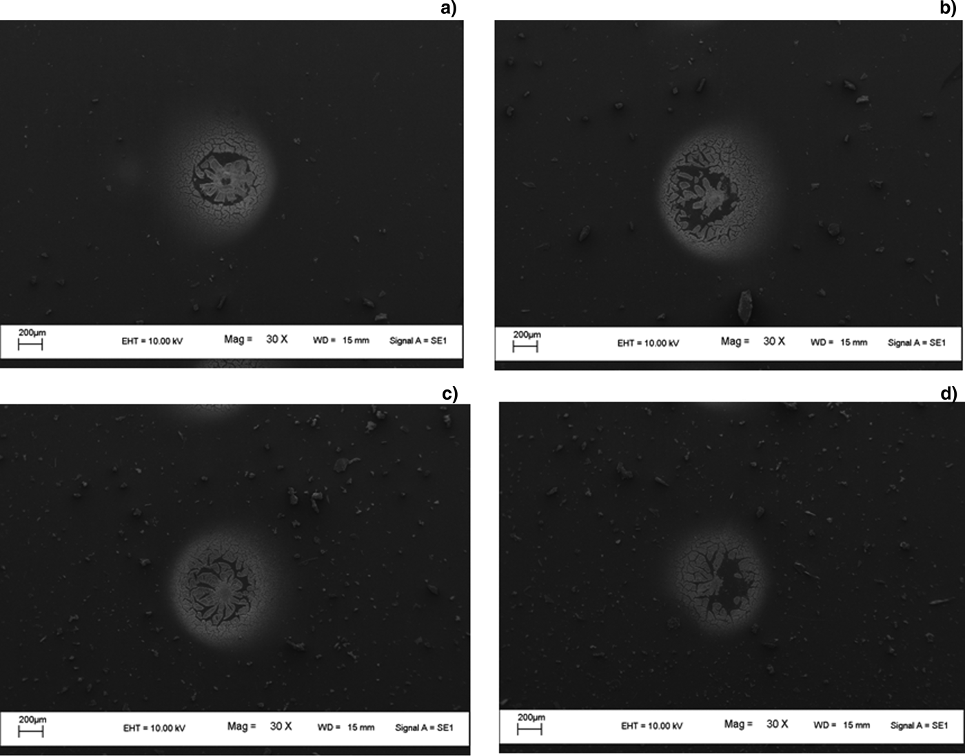
We now focus on re-deposited films on acceptor substrates. Variation in laser energy and speed of translation is expected to affect the ejected material and, hence, the LIFT patterns that result. Figure 5 shows SEM images of re-deposited indium. The laser energy was varied from 93 nJ to 19 nJ, keeping the translation speed of the donor substrate constant at 1 mm/s. The accepter substrate was kept stationary during these measurements. All the images in Figure 5 appear to show a void in the central region of the deposition zone. This may be caused by back-ejection of ablated material from the center portion of the laser beam which has the highest intensity. This central material is energetic (“hot”) for effective bonding to occur with the glass substrate. Indications of such effects have been reported in earlier work by Bera et al. (Reference Bera, Sabbah, Yarbrough, Allen, Winters, Durfee and Squier2007) and Klini et al. (Reference Klini, Loukakos, Gray, Manousaki and Fotaki2008). A “splashing” effect can also be discerned in Figure 5.
SEM images of LIFT patterns at 1 mm/s translation speed of the donor substrate at laser energies of (a) 93 nJ, (b) 74 nJ, (c) 37 nJ, and (d) 19 nJ.
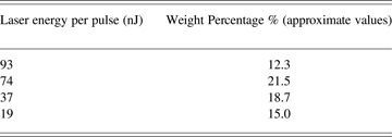
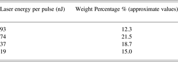
Table 1 shows the weight percentage of individual dots of indium deposited on the acceptor substrate for different laser energies, with the weight percentage values deduced from EDAX analysis. For the weight percentage measurement, region around deposited spot was considered and Indium proportion was measured as against substrate material. It follows the trend that can be visualized in Figure 5: the highest laser pulse energy (93 nJ) yields less weight percentage of indium compared to the corresponding pattern we obtain using 74 nJ energy. Although it would be expected that more ejected particles/material would be obtained at higher energies, like 93 nJ, the ejected material apparently becomes too “hot” at high values of incident laser energy for effective bonding to occur with the glass substrate, resulting in a lower weight percentage of re-deposited indium at 93 nJ compared to at 74 nJ.
Variation of weight percentage of re-deposited indium on acceptor substrates with laser energy
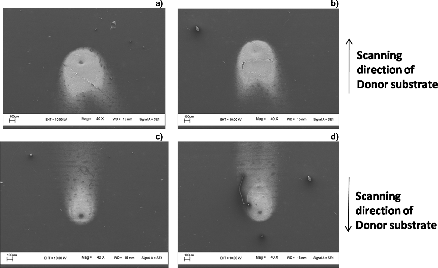
SEM images of re-deposited indium at 5 mm/s and 10 mm/s scanning speed for 37 nJ and 19 nJ laser energies are shown in Figure 6. The accepter substrate was again kept stationary for these measurements. The images show a comet-like pattern that seems to propagate in the direction of scanning. In Figures 6c and 6d, the donor substrate was moving in the opposite direction to that in Figures 6a and 6b. It can clearly be seen from Figures 6a and 6c (or from Figs. 6b and 6d) that the length of the comet tail increases with increasing scanning speed.
SEM images of indium dots for various energy and scanning speed values. (a) 37 nJ and 5 mm/s, (b) 19 nJ and 5 mm/s, (c) 37 nJ, and 10 mm/s, and (d) 19 nJ and 10 mm/s. The scanning direction of donor substrate for (a) and (b) are the same and, similarly, the scanning direction for (c) and (d) are the same, as indicated by the arrows shown in the figure.
On comparing Figure 6 with Figure 5, it is observed that the deposition seen in Figure 6 consists of finer particles than in Figure 5. Furthermore, the voids in the middle region are reduced to great extent in Figure 6 compared to Figure 5. We attribute this to two main reasons: first is the reduction in energy density (dose) due to increased scanning speed and, the second is ejected material now seems to have two major velocity components, one in the direction of laser propagation and other in the direction of donor substrate translation.
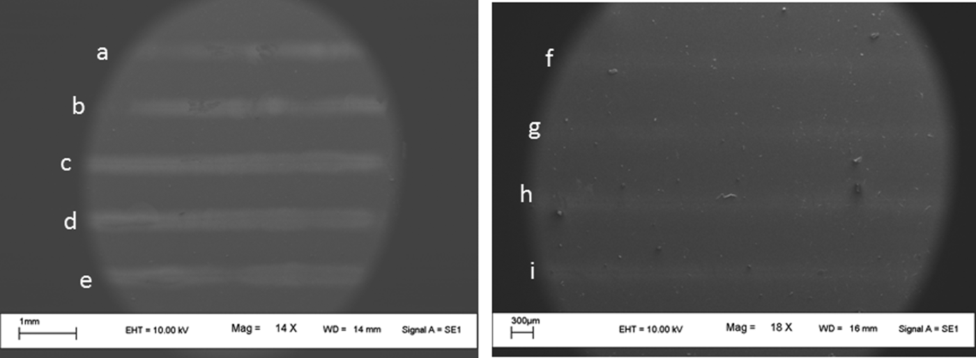
The concomitant movement of the acceptor substrate along with the donor substrate enabled us to write a LIFT line. Figure 7 shows some typical SEM images of LIFT line-patterns that we wrote using different laser energies, at 1 mm/s and 5 mm/s scanning speed for both the accepter and donor substrates. The geometry of the LIFT pattern was found to be dependent on the relative motion of acceptor substrate with donor substrate, which in this case was kept at zero. All the LIFT patterns in Figures 7a–7i show linear deposition of indium. Figures 7a–7e correspond to laser energies 93 nJ to 19 nJ, with 1 mm/s scanning speed; Figures 7f–7i correspond to laser energies 93 nJ to 37 nJ, with 5 mm/s scanning speed. Low visibility (and also less width) of the deposition in Figures 7f–7i compared to that shown in Figures 7a–7e is attributed to higher scanning speed (5 mm/s) as the relative motion of the acceptor substrate and donor substrate was kept zero in both cases. At 19 nJ laser energy and 5 mm/s translation speed, deposition was not visible.
SEM images of linear LIFT patterns for various laser energies and scanning speed values. Energies used for deposition of lines are (a) 93 nJ (b) 74 nJ, (c) 56 nJ, (d) 37 nJ, (e) 19 nJ, (f) 93 nJ, (g) 74 nJ, (h) 56 nJ, and (i) 37 nJ. For lines (a) to (e) scanning speed of 1 mm/s was used and for lines (f) to (i) scanning speed of 5 mm/s was used.
4. SUMMARY
LIFT patterns of indium have been written by us using nJ energy laser pulses from a femtosecond laser oscillator. The effects of laser energy and scanning speed have been explored. Optimization of the scanning speed is required to avoid voids in the central portion of the LIFT pattern, and also to avoid a “splashing” effect. Interesting comet-like patterns have been discovered at higher speeds; this pattern gives way to more minute particles being re-deposited at intermediate or low speeds. It is shown that, by controlling the relative motion between the acceptor and donor substrates, some measure of control can be exercised on the geometry of the LIFT pattern.
ACKNOWLEDGEMENT
This work constitutes part of the activities of I-CUP, the Indian Cluster for Ultrafast Photonics, which is supported by the Office of the Principal Scientific Adviser to the Government of India.