I. INTRODUCTION
The most important oxide for luminescent applications is yttrium aluminum garnet or YAG with chemical formula Y3Al5O12. Cerium-doped YAG is an important photoluminescence material used in scintillators and for white light production in solid state light emitters. Scintillators are optical materials that emit pulses of visible photons when excited with high energy radiation. Gamma ray spectrometers providing high sensitivity and effective isotope identification require high energy resolution, high effective atomic number and scintillators that can be produced with large sizes.Reference Wang, Zhang, Luo, Gu, Tang, Dong, Tan, Que, Zhang, Li and Kong1 Recently, polycrystalline ceramics have been developed to the point where they can compete with the performance of single crystals for light emitting applications.Reference Ikesue2,Reference Ikesue, Aung, Yoda, Nakayama and Kamimura3 When Ce:YAG is excited by light in the blue range, it produces yellow light that, when combined with the incident blue light, appears bright white to the human eye. Most work done on Ce:YAG so far has been about single crystals, but polycrystalline ceramic Ce:YAG has a serious potential for efficient white light production.Reference Penilla, Kodera and Garay4
Ceramic single crystals are often transparent in the optical visible range due to their relatively high band gaps (>3.1 eV). However, their polycrystalline counterparts are translucent or opaque due to the severe scattering of light by defects such as pores and grain boundaries.Reference Chaim, Kalina and Shen5 To achieve optical transparency, it is imperative to eliminate the presence of pores and secondary phases. YAG is a stoichiometric compound and any shift from the stoichiometric composition entails an appearance of a secondary phase.Reference Frage, Kalabukhov, Sverdlov, Ezersky and Dariel6
In the field of plasma spraying, there exist only rare works describing the preparation of pure YAG (without any dopant). Moreover, phase transformations, often manifested in the sprayed materials, can be accompanied by detrimental volumetric changes leading to spallation of the coating.Reference Weyant and Faber7 YAG, considered to be a promising high-temperature ceramic, was prepared using precursor plasma spraying,Reference Parukuttyamma, Margolis, Liu, Grey, Sampath, Herman and Parise8 and the precursor sol was sprayed using radio-frequency induction plasma technique. Analysis of the as-sprayed coatings confirmed that metastable hexagonal yttrium aluminate (H-YAlO3) was the major phase. Pure YAG is also considered to be the oxygen barrier in a thermal barrier coating system due to its low oxygen diffusivity relative to stabilized zirconia ceramics and its comparatively low thermal conductivity at high temperatures.Reference Weyant and Faber7 In the experiment in which the main motivation was to find a replacement for zirconia, the crystallinity of the as-sprayed YAG coatings was the highest at high power and short spray distances were used for the spray setup adjustment. Additional heat treatment of the coatings was reported in the same studyReference Weyant and Faber7 as an efficient way to obtain highly or fully crystalline YAG material.
An Al2O3/YAG nanocomposite coating has already been prepared using plasma spraying.Reference Suzuki, Sodeoka, Inoue, Murakami and Sasaki9 There are very scarce reports that a cubic YAG phase is maintained during the spraying process as well as after heat treatment, and it has been reported that the extensive phase stability is a big advantage of the YAG (as an oxygen barrier material) over, e.g., alumina that are well known for their multiple crystallographic transformations and a vast array of polymorphs.Reference Su, Trice, Faber, Wang and Porter10
The aim of our work was to test the influence of the plasma spray process on the structure and optical properties of Ce:YAG material. We used crushed Ce:YAG single crystals to form a spray feedstock powder instead of any precursor with composition different from Ce:YAG, which is a more frequently reported approach even for pure YAG.Reference Weyant and Faber7,Reference Su, Trice, Faber, Wang and Porter10 Two spraying techniques have been used, i.e., a water-stabilized plasma (WSP) gun as well as a more conventional gas-stabilized plasma (GSP) gun to compare these two processes. Both spray processes were applied at an ambient atmosphere (the so-called atmospheric plasma spraying). When useful, the prepared coatings were compared with Ce:YAG single crystals from which the spray powder stems. According to our knowledge, Ce-doped YAG was never reported as plasma sprayed. The main driving force behind our efforts was an idea to produce large-area scintillators by plasma spraying.
II. EXPERIMENTAL
A. Powders and spraying
Single crystals of YAG doped with 5 mol% of Ce were obtained from Crytur Ltd. (Turnov, Czech Republic) as fragments having the same physical nature but not shapes and sizes as real industrial single-crystalline products.
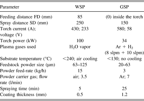
Milling and sieving were applied to make a fine powder for spraying. Two different powder size classes for the two applied spray techniques were obtained (Table I). The final feedstock powder appearance was broken-glass-like including needle-shaped particles and sharp faceted particles. Plasma torch Plasmatechnik F4 (Sulzer Metco, Winterthur, Switzerland) was used for GSP spraying (Fig. 1) and argon was used as a powder feeding gas. Stainless steel coupons and YAG single crystals (without Ce) were used as substrates. The coatings adhered on materials with relatively large variety of thermal expansion coefficient. Some of the coatings were intentionally stripped off by a low-temperature/large cooling rate thermal cycling due to a thermal expansion mismatch between Ce:YAG and stainless steel. The substrate temperature, which was monitored during the spraying by a two-color pyrometer, did not exceed 130 °C.
Parameters used for spraying.

GSP torch scheme.
The other type of samples was produced using the high-feed rate water-stabilized spray system (WSP, Fig. 2) at Institute of Plasma Physics (Prague, Czech Republic).Reference Hrabovsky11 Stainless steel coupons and YAG single crystals (without Ce) were used as substrates. Compressed air was used for powder feeding as well as for cooling of the substrate and of the freshly deposited coating. At WSP, the cooling setup consisted of a tube with compressed air, installed on the same robotic arm as the torch and repeating the torch movement patterns just few tens of seconds behind the plasma jet. During both spray processes, the substrate was fixed without any motion. The temperature, which was monitored by an infrared camera, did not exceed 240 °C. Because of higher power of this spray torch, as compared to GSP, a similar time cycle during spraying brings remarkably higher substrate temperature. It should be mentioned that WSP applies much higher thermal load first of all onto the sprayed material than GSP.
WSP torch scheme.
Due to this risk of overheating and structural damage, only relatively thin coatings were realized by WSP. Such coatings could not be separated from the substrate (because of thermal expansion mismatch between Ce:YAG and stainless steel) and therefore were unsuitable for the study of thermal post-treatment effect on the recrystallization. YAG single crystal substrates (without Ce) were too heat-sensitive and after spraying by both techniques exhibit cracks and coating delaminations. Moreover, the adhesion of the WSP coating to the polished surface single crystal YAG was poor and sand blasting of the single crystal surface to provide better adhesion was not possible because the single crystals fractured.
Heat post-treatment of selected coatings was done in a programmable laboratory furnace (Clasic, Czech Republic) in air atmosphere, with a dwell time of 15 min on the maximal temperature, whereas ramps 10 °C/min were used for heating and cooling.
B. Characterization techniques
Density was examined by helium pycnometry (AccuPyc 1330 V3.03). The porosity was studied by optical microscopy on polished cross sections, with the micrographs taken with a CCD camera and processed using an image analysis (IA) software (Lucia G, Laboratory Imaging, Czech Republic). Five images of microstructures taken from various areas of a cross section for each sample were analyzed. The used magnification was 400 in all cases. For a better description of the porosity, certain additional criteria were introduced.Reference Ctibor, Neufuss and Chraska12
The samples were analyzed on x-ray powder diffractometer D8 Discover, which was equipped with 1D LynxEye detector and xyz positioning system with laser check enabling precise alignment of the sample compliant with requirements of Bragg–Brentano focusing geometry. Filtered Cu Kα radiation was used in the 2θ range from 10 to 90°.
Setaram TG-DTA 92 machine was used for differential thermal analysis Plasma sprayed sample was manually milled to powder with a grain size comparable with the size of initial feedstock powder. As a reference, substance α-Al2O3 powder (grain size <60 µm) was used. Mass of each measured sample was 50 mg. All experiments were performed with a heating rate of 5 °C/min and a dwell time of 15 min at the maximum temperature.
The microhardness was measured by Hanemann microhardness head (Zeiss, Germany) mounted on an optical microscope with a fixed load of 1 N and Vickers indenter. Twenty indentations from various areas of a cross section for each sample were analyzed.
The diffuse reflectance was measured by UV-VIS-NIR scanning spectrophotometer (Shimadzu, Japan) with a multipurpose large sample compartment and the corresponding band gap energy was estimated. The reflectance curves were obtained between 250 and 2000 nm.
Cathodoluminescence (CL) is an effect arising in compounds which, under high-energy electron beam irradiation emits light of wave lengths in the range between approximately 200 and 1200 nm. The yttrium-containing oxides such as Y2O3, YAG, and YAlO3 exhibit significant CL response.Reference Gil, Naumenko, Vassen, Toscano, Subanovic, Singheiser and Quadakkers13 The CL spectra are characteristics of the compound, whereas the number of peaks, their positions and intensities are very sensitive to the defect structure and impurity ions. Scanning electron microscope Tescan Vega was used with 30 keV electron energy. The CL signal was detected by AVANTES AvaSpec-2048, integration time 5 s.
III. RESULTS AND DISCUSSION
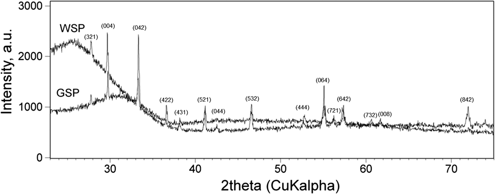
The only crystalline phase detected by XRD in the as-sprayed coatings was Y3Al5O12 (PDF No. 033-0040), Fig. 3. The YAG composition at equilibrium represents 37.5 mol% of Y2O3 in Al2O3.Reference Ullal, Balasubramaniam, Gandhi and Jayaram14,Reference Ravi, Gandhi, Guo, Margolies and Sampath15 However, a significant extension of the existence of stoichiometric YAG toward the Y2O3-rich side of the phase diagram was reported.Reference Parukuttyamma, Margolis, Liu, Grey, Sampath, Herman and Parise8 High portions of the material of our coatings of our coatings was in the amorphous state (the halo below 37°2 theta). Cerium-containing phase was not detected, which suggested that Ce3+ ions were dispersed more in the glass matrix to some extent rather than completely incorporated into crystal lattice.Reference Wang, Mei, He, Liu, Li and Xu16 This might affect the luminescence of Ce:YAG glass-ceramics.Reference Wang, Mei, He, Liu, Li and Xu16
XRD of WSP and GSP coatings.
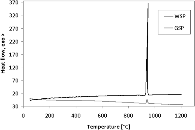
The exothermic peak at 930 °C on DTA curve of both GSP and WSP coatings, Fig. 4, signalizes crystallization of the amorphous fraction in the coating. Around this temperature we have selected a set of temperatures for the heat post-treatment.
DTA curve of the GSP and WSP coatings.
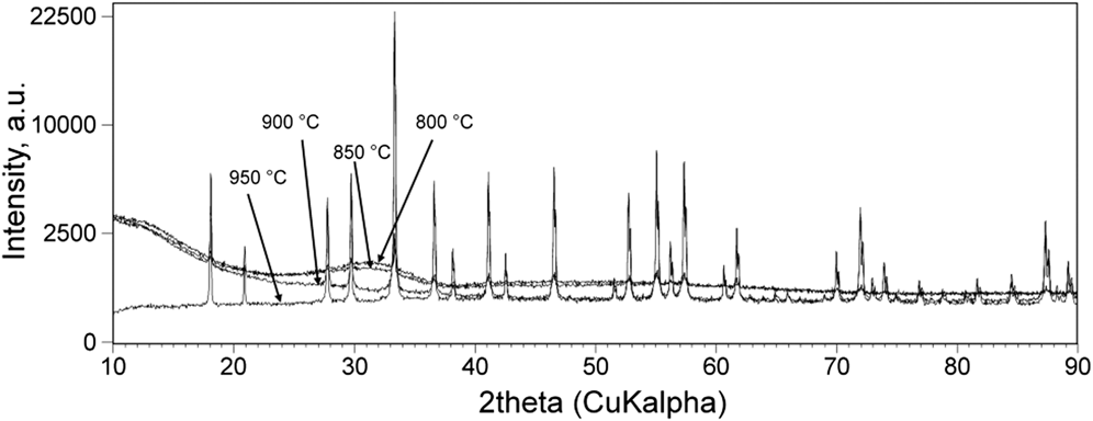
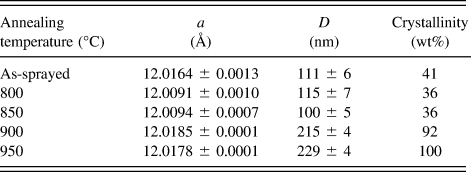
Heat post-treatment of the GSP-sprayed self-standing plates in air at 800, 850, 900, and 950 °C has been executed with the purpose to ensure crystallization of the amorphous fraction at as low thermal load as possible. The x-ray diffraction patterns of heat-treated coatings, Fig. 5, show the presence of only one crystalline phase, i.e., cubic YAG belonging to Ia-3d space group. Amorphous bumps or halos are clearly visible in all the diffraction patterns except for those of the samples annealed at 900 and 950 °C. Rietveld refinement performed in TOPAS 4.2 was done to evaluate the lattice parameter and compute the sizes of coherently scattering domains D from the values of diffraction profiles′ integral breadths. To compare the samples relatively, and not absolutely, from the amorphous fraction point of view, crystallinity was estimated in Diffrac Eva software taking into consideration the 2θ range from 22 to 68°. The results of crystallinity estimations are as follows: as-sprayed – 41%; 800 °C – 36%; 850 °C – 36%; 900 °C – 92%; and 950 °C – 100%. Other data are in Table II.
XRD of GSP samples with various heat-treatment.
Results of Rietveld refinement (only for GSP samples) lattice parameter a (Å) and mean sizes of coherently scattering domains D (nm) (i.e., crystallite size). Crystallinity estimated from diffraction in the 2θ range from 22 to 68°.
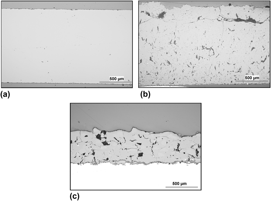
Microstructure of the coatings is presented in cross-sectional micrographs taken by a light microscope, Fig. 6. The GSP coating was self-standing and comparably thick as the available single-crystal plate, whereas the thinner WSP coating adhered on a steel substrate (white). The gray layer between the substrate and coating is a gap filled with the mounting resin; partial loss of adhesion took place at the coating cutting for the materialographic treatment.
(a) Single crystal, cross-section; (b) GSP coating, cross-section; (c) WSP coating, cross-section (substrate white).
As expected, the coatings contained markedly more defects compared to the single crystal. Porosity of both coatings was similar and relatively low as documented in Table III. However, the pore size expressed as “equivalent diameter” (E.D.) was nearly double for the WSP coating. The number of pores per meter square was correspondingly higher for GSP, which means that this coating had high amount of rather small pores and the WSP coating a smaller quantity of larger pores, see Figs. 6(b) and 6(c). Circularity (CIR) describes mean anisotropy of pore shapes. Zero (0) means flat pores and unit (1) means ideally globular pores. Pores in GSP were flatter, mainly due to cracking in the vertical direction, see Figs. 6(b) and 6(c). Minimal detected circularity (CIRmin) is similar for both coating types – individual cracks or flat pores were present in both coating types. The single-crystal had different character; its pores were significantly finer (E.D. under 1 µm), porosity far under 1%, and CIR of pores extremely high. Taking into account the differences between spray techniques and single-crystal manufacturing procedures, the observed difference was expectable. Concerning the differences between GSP and WSP, the finer feedstock powder and lower thermal load at GSP brought finer pores. Also, its surface roughness R a (measured by a contact tip of Surtronic 3P, Taylor-Hobson, UK) was lower: 9.5 ± 1.2 µm instead of 24.5 ± 2.4 µm for WSP.
IA of pores and microhardness of the coatings.
a Only informative value; the approach and magnification selected for GSP and WSP were not suitable for a statistically relevant examination of the single crystal.
The density of the GSP coating increased with annealing as follows (annealed in air, dwell time 2 h): as-sprayed – 4.1665 g/cm3; at 850 °C – 4.2118 g/cm3; at 1100 °C – 4.3265 g/cm3. The theoretical density of YAG is about 4.56 g/cm3.
The microhardness was slightly higher for WSP, see Table III. The single crystal was even markedly harder which implies from the processing used.
The transparency of the Ce:YAG glass-ceramics is blocked by the structural defects usually serving as light-scattering centers.Reference Ravi, Gandhi, Guo, Margolies and Sampath15 This situation was relevant also to our coatings.
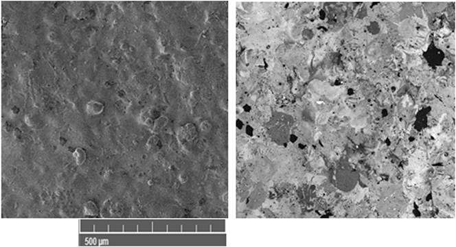
Generally, in plasma-spray coatings, porosity can result from shadow effects during the splashing of particles on previously arrived splats, holes, or gas inclusions between splats, large, unmelted particles, and explosion of overheated particles on impact.Reference Weyant and Faber7 Individual splats are visible in Fig. 7, namely in the right part (CL mode) as circular-like areas with a typical dimension of about 100 µm. Several of them are dark gray (poor CL), several nearly white (pronounced CL), and the rest is pale gray. So, the surface is inhomogeneous from the viewpoint of CL.
SEM of the GSP sample; left: SE mode, right: CL mode.
To observe the sensitivity of CL on the thermal post-treatment, WSP samples sprayed on YAG single crystal substrates (without Ce), however having poor mechanical integrity, as mentioned in 2.1, were subjected to annealing to 1000 and 1250 °C for 12 h. As depicted in Fig. 8, the position of the broad emission band was almost independent of the thermal history of the sample, and the full width at half maximum was about 90 nm. This quite symmetric luminescence peak at around 530 nm is assigned to the transitions of Ce3+ (Ref. Reference Kareiva17). Ce3+ with 4f1 electron configuration has two ground states of 2F5/2 and 2F7/2 because of the spin–orbit interaction.Reference Kasuya, Isobe and Kuma18 In our case, the maximum CL intensity was at 550 nm.
CL spectra of WSP coatings with and without thermal annealing; inset: the same spectra depicted with normalized intensity.
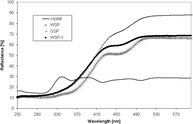
It is visible from the diffuse reflectance examination of coatings, Fig. 9, that on curves corresponding to both coatings absented the reflection peak at about 340 nm, typical for the single crystal. The coatings reflect much more radiation than the single crystals at wave lengths over 390 nm, i.e., in the visible spectral region. In this region, the GSP coating is even more reflective than the WSP coating, which exhibits a plateau between 420 and 460 nm that is only insinuated in the case of GSP. The WSP coating sprayed onto YAG single crystal (without Ce), label WSP-Y, was below 410 nm (very similar to GSP coating) and above 500 nm (similar to WSP coating on steel). Based on diffuse reflectance, which omits the microstructural defects and responds strictly on electron band structure of the material, we could predict the better visible light emission for plasma sprayed samples than for the single crystal. But, in real scintillating action, where not only the surface is important but also the sample interior, this advantage was not applicable, see next figures.
Reflectance results; WSP-Y means WSP Ce:YAG coating on YAG single crystal.
Figure 10 presents the response of illumination with a 366 nm lamp (NU-8 CML, Konrad Benda, Germany). It shows that the GSP coatings heat-treated at 900 and 950 °C, which were nearly or fully recrystallized, exhibited yellow light emission, whereas the remaining two samples heat-treated at lower temperatures and predominantly amorphous, appear much darker.
Macro-photograph of the heat-treated GSP samples illuminated with a 366 nm lamp; from the left 800, 850, 900, and 950 °C.
All GSP heat-treated coatings exhibit only Y3Al5O12 as the crystalline phase, Fig. 5. The occurrence of only Y3Al5O12 in both GSP and WSP coatings is a significant distinction from reported coatings sprayed from precursors,Reference Ravi, Gandhi, Guo, Margolies and Sampath15 which did not attain the desired phase composition of single-phase cubic YAG. Annealing at 900 °C/20 min is reported to lead to mixed YAG plus amorphous phase plus hexagonal YAlO3, whereas 80 min on the same temperature was necessary for obtaining pure crystalline YAG phase.Reference Ravi, Gandhi, Guo, Margolies and Sampath15 In the case of our coatings, Ce did not create any individual phase and is not detected by XRD; however, it can be present as a substitutional or interstitial atom in a fairly complex cubic lattice with Ia-3d space group. The presence of Ce3+ in garnet structureReference Mancic, Marinkovic, Marinkovic, Dramicanin and Milosevic19 is apparent due to the increase of lattice parameter a comparing with pure YAG (free of Ce3+), which is 12 Å.Reference Mancic, Marinkovic, Marinkovic, Dramicanin and Milosevic19 An increase of the unit cell parameters, Table II, and bond lengths are indicative in our samples implying that Y3+ (90 pm) was partially substituted by bigger Ce3+ (102 pm). The refined lattice parameter a was in the range from 12.0091 to 12.0185 Å for GSP samples heat-treated at 800 and 900 °C, respectively. These values obtained by Rietveld refinement fall into the existent range between YAG Crystallographic Information Files in the ICSD database and the presence of cerium cannot be, thus, reliably affirmed. The increase of crystallite size, or more precisely said coherently scattering domains, from approximately 100 nm in as-sprayed, 800 and 850 °C to about 220 nm for 900 and 950 °C mirrors rather grain coarsening due to recrystallization than any phenomena connected with ceria atoms substituting yttria atoms in the cubic lattice.
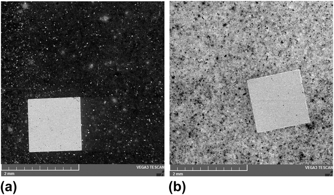
Figure 11 gives a comparison of Ce:YAG single crystal and the heat-treated GSP coating in the CL mode of SEM. We can see a large difference between 850 and 900 °C heat treatment. The intensity of CL of the coating annealed at 900 °C is similar to Ce:YAG single crystal, but less homogeneous. The emission intensity is influenced by crystallinity as well as microstructure imperfections such as splat boundaries, pores, and thin cracks that were healed partially by heat treatments. Good scintillation response requires good crystallinity as well as freedom from macroscopic defects. From our measurements and CL comparisons to single crystal Ce:YAG, we estimate the emission intensity of the best sprayed samples is about 40% of the comparably doped single crystal Ce:YAG.
CL of the heat-treated GSP samples (the small square lying on the sample is a single crystal) from the top: 850 and 900 °C.
IV. CONCLUSIONS
Yttrium–aluminum garnet doped with Ce was plasma sprayed using two different processes – GSP torch and WSP torch. Mainly free-standing plates were obtained by GSP, whereas WSP led to thinner coatings adhering on substrates. Amorphous fraction was present in both types of coating. Due to its presence, we attempted to improve the crystallinity via heat treatment. By heating, the material was crystallized at 930 °C. The mere 15-min heat treatment at 950 °C in air led to fully crystalline single-phase cubic YAG. The GSP samples were subjected to heat treatments around the crystallization temperature and after it exhibited increased emission intensity at 550 nm more like single crystal YAG. The luminescence intensity was not homogeneous over the surface of the sample due to splat boundaries, porosity, and cracks. Further improvements in the plasma spray parameters and improvements in the annealing conditions (time, temperature, and atmosphere) could result in a useful method for preparing large area free-standing plates with good optical emission.
ACKNOWLEDGMENT
The authors from IPP ASCR acknowledge the support of the Czech Science Foundation under No. P108/12/1872. The author from Crytur Ltd., Turnov, Czech Republic, acknowledges the project No. TA 1011017 granted by the Technology Agency of the Czech Republic. The GSP spraying was done by S.A.M. Holding, Miletin, CZ.