Introduction
Potential of the ceramic–polymer composites is well realized because such a material system can effectively integrate the compressive strength and fracture toughness of the ceramic and polymer phases, respectively [Reference Wegst, Bai, Saiz, Tomsia and Ritchie1, Reference Ritchie2, Reference Acharya and Mukhopadhyay3, Reference Deville, Saiz, Nalla and Tomsia4]. Among the different composite architectures, multilayered ceramic–polymer composite morphology is of particular interest. One approach to developing multilayered ceramic–polymer composites is the infiltration of open-cell sintered ceramic foam in the polymer phase, followed by in situ polymerization. This methodology would require fabrication of ceramic foam with lamellar/dendritic (multilayered) morphology and directional porosity; however, the challenge is that the available techniques typically yield an isotropic pore morphology with random orientations of pores. The ice-templating technique, on the other hand, produces macroporous ceramic with a lamellar/dendritic morphology and directional porosity, in which parallel ceramic walls (oriented in the direction of the temperature gradient applied during ice-templating) are connected in the transverse direction through ceramic bridges [Reference Wegst, Bai, Saiz, Tomsia and Ritchie1, Reference Deville, Saiz, Nalla and Tomsia4, Reference Porter, Imperio, Wen, Meyers and McKittrick5, Reference Ghosh, Dhavale, Banda and Kang6, Reference Ghosh, Kang, Banda and Kamaha7, Reference Ghosh, Banda, Kang and Dhavale8, Reference Deville9]. Owing to low pore tortuosity, ice-templated porous ceramic can be infiltrated with polymer solution to synthesize multilayered ceramic–polymer composites [Reference Deville, Saiz, Nalla and Tomsia4, Reference Deville, Meille and Seuba10, Reference Liu, Zhu, Jiao, Weng, Zhang and Ritchie11]. Although there are studies on the 3-point bend response and fracture toughness measurements of ice-templated composites, their compressive deformation behavior remains relatively less explored. Lightweight ceramic–polymer composites are ideal structural material candidates for mechanical load-bearing applications including dynamic (high strain rate) loading conditions, where materials are subjected to compressive loading conditions.
For ice-templated ceramic–polymer composites, compressive response will not only depend on the composition but also on the loading direction. Therefore, for compression direction parallel to the layers, the ceramic phase will tend to dominate the macroscopic mechanical response and it is expected that the compressive strength of the composite will be maximum along this orientation. Because the changes in the microstructure of the ice-templated ceramic materials influence their compressive mechanical properties [Reference Porter, Imperio, Wen, Meyers and McKittrick5, Reference Ghosh, Dhavale, Banda and Kang6, Reference Ghosh, Kang, Banda and Kamaha7, Reference Ghosh, Banda, Kang and Dhavale8], such variations may also affect the compressive response of the resulting composites. Another important aspect is to address the compressive deformation behavior of ice-templated composites with respect to the compressive response of the individual components, i.e., ice-templated porous ceramic and polymer phases. To evaluate the performance of the composites in the dynamic loading environments, it is also crucial that the compressive response of the composites is characterized both at quasistatic (low strain rate) and dynamic (high strain rate) regimes of strain rate.
In this study, to address the above aspects, ice-templated porous alumina (Al2O3) ceramics were developed from aqueous suspensions of the same concentration (20 vol% Al2O3), but freezing front velocity (FFV) during the ice-templating process was systematically varied to alter the microstructure of the resulting porous ceramics. An ultrafine Al2O3 powder (d 50 = 300 nm) was utilized based on our earlier studies, which showed that finer ceramic powder particles produce ice-templated ceramics with dense lamella walls [Reference Ghosh, Dhavale, Banda and Kang6, Reference Ghosh, Kang, Banda and Kamaha7, Reference Ghosh, Banda, Kang and Dhavale8]. Next, the porous ceramics were infiltrated with epoxy, which was followed by in situ polymerization to develop the composites. To understand the loading rate effects, uniaxial compressive response of the resulted composites was evaluated both in the quasistatic (∼10−3 s−1) and in the dynamic (≥102 s−1) regimes of strain rate. In addition to the mechanical characterization of the ice-templated Al2O3–epoxy composites, compressive mechanical response of the individual components (i.e., ice-templated porous Al2O3 and epoxy) was investigated. The deformed ice-templated composites were characterized using scanning electron microscopy (SEM) to understand the possible origins of the observed failure response.
Results and discussion
Microstructural characteristics of ice-templated sintered alumina materials
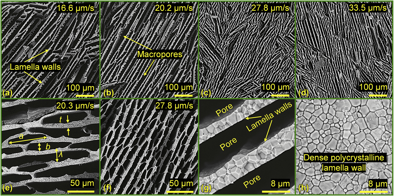
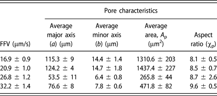
Representative microstructures of the ice-templated porous Al2O3 materials, which were processed at four different FFVs, are shown in Figs. 1(a)–1(d). Characteristic microstructural differences are observed in terms of the lamella wall thickness (t) and lamella wall spacing (i.e., wavelength, λ), where both the parameters decreased with increasing FFV. It can also be observed that there is a decrease in the pore size (pore major axis, a, and minor axis, b) as well with the increasing FFV. Figures 1(e) and 1(f) show higher magnification SEM micrographs of ice-templated sintered Al2O3 materials processed at 20.2 µm/s and 27.8 µm/s, respectively, which reveal the significant decrease of t and λ, and pore size with increasing FFV. Average values of the microstructural parameters such as a, b, pore area (A P = π/4 × a × b), and pore aspect ratio (χp = a/b) are provided in Table I.
Representative SEM micrographs of ice-templated sintered porous Al2O3 materials that were processed at (a) 16.6 μm/s, (b) 20.2 μm/s, (c) 27.8 μm/s, and (d) 33.5 μm/s FFV, respectively. With the increase in FFV, the macropores retain elliptical pore morphology. However, significant decrease in pore major axis (a), pore minor axis (b), lamellae spacing (λ), and lamellae thickness (t) occurred with the increasing FFV, which can also be seen in (e) and (f) (ice growth direction below and above the page). High magnification SEM micrograph observed from (g) cross-section of porous Al2O3 (ice growth direction below and above the page) shows long slender dense ceramic lamella walls and (h) revealing the homogeneous dense polycrystalline microstructure in the lamella wall (ice growth parallel to the page).

Variation of pore characteristics in ice-templated porous Al2O3 materials as a function of FFV: major axis (a), minor axis (b), pore area (A p), and aspect ratio (χp).

Variation of density and porosity with FFV
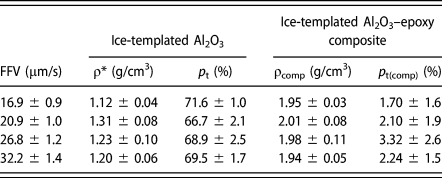
The average values of density and porosity of ice-templated Al2O3 materials are listed in Table II. It appears that initially average density (ρ*) and porosity (p t) of ice-templated Al2O3 materials increased and decreased, respectively, with increasing FFV, whereas a further increase of FFV seems to cause a slight decrease and increase of ρ* and p t, respectively. Maximum and minimum ρ* values were observed to be 1.46 g/cm3 and 1.04 g/cm3, respectively, whereas minimum and maximum p t values were observed to be 63 vol% and 74 vol%, respectively. Figure 1(g) shows a high magnification SEM micrograph of the cross-section of a lamella wall of the sintered Al2O3 processed at 32.9 µm/s, whereas Fig. 1(h) shows the high magnification image of a lamella wall. Both Figs. 1(g) and 1(h) reveal the fine, polycrystalline microstructure of lamella walls and no visible porosity can be observed within the walls. Therefore, it can be assumed that in the sintered Al2O3 materials total pore volume corresponds to the macropores (i.e., macroporosity) present in between the dense lamella walls. Table II also shows the variation of average ρcomp and p t(comp) of ice-templated Al2O3–epoxy composite specimens with average FFV. The maximum and minimum ρcomp values were observed to be 2.16 g/cm3 and 1.80 g/cm3, respectively, whereas the minimum and maximum p t(comp) values were observed to be 0 vol% and 10.6 vol%, respectively. Although from microstructure analysis the locations of porosity were not apparent in the composites, it is speculated that porosity originated due to the incomplete infiltration of epoxy in ice-templated Al2O3.
Variation of density and porosity of ice-templated porous Al2O3 materials and ice-templated Al2O3–epoxy composites as a function of FFV.

Uniaxial compressive response at quasistatic regime of strain rate
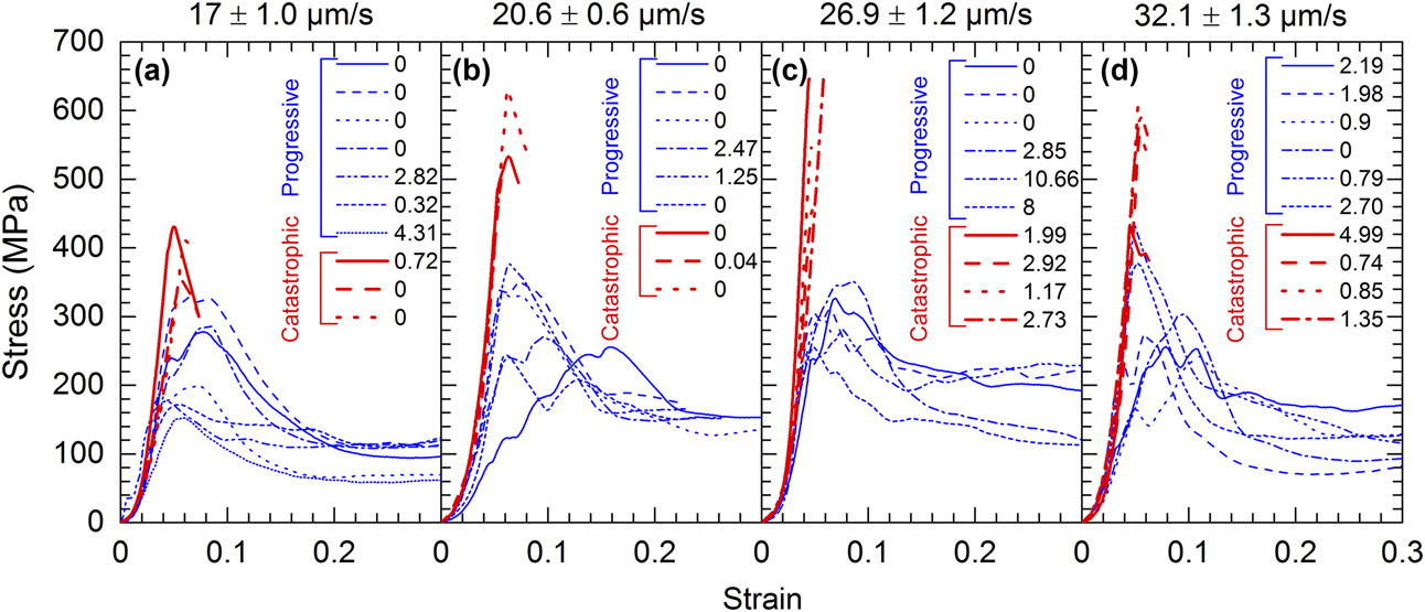
Figure 2 shows the quasistatic (strain rate ∼10−3 s−1) stress–strain response of the ice-templated composites, up to 0.3 strain. In each figure, the average FFV value corresponds to the freezing condition for ice-templated Al2O3 materials, which were infiltrated to develop the ice-templated composites. All the composites exhibited a linear stress–strain response up to the peak stress (referred to as σp). Interestingly, at each FFV regime, a considerable difference in the overall compressive stress–strain curves is observed depending on the deformation response beyond peak stress. Mainly, two distinct features are noticeable in the measured compressive response. One set of composites exhibited a compressive response where stress dropped abruptly beyond peak stress (red curves), and we refer the failure type as catastrophic, i.e., a sudden loss of the compressive load-bearing capacity. Whereas the other set of composites exhibited a compressive response where stress is observed to decrease gradually beyond peak stress (blue curves), which we refer to as progressive-type failure. At each FFV regime, σp values corresponding to catastrophic-type failure are observed to be significantly greater in comparison to that corresponding to progressive-type failure.
Uniaxial quasistatic compressive stress–strain response of ice-templated Al2O3–epoxy composites processed at average FFV of (a) 17 ± 1.0 μm/s, (b) 20.6 ± 0.6 μm/s, (c) 26.9 ± 1.2, and (d) 32.1 ± 1.3 μm/s. The numerical values shown in legend represent porosity (vol%) in composite. The compressive stress–strain curves shown in blue color correspond to progressive-type failure in composites, whereas the stress–strain curves shown in red color correspond to catastrophic-type failure in composites.

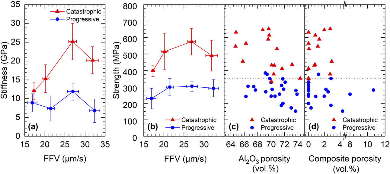
Owing to the significant scatter in the σp values at each FFV regime, it is appropriate to group the stress–strain curves based on the type of compressive response (catastrophic failure versus progressive failure) and for each group plot the average stiffness and strength values as a function of average FFV, which is presented in Fig. 3. At each FFV regime, average stiffness corresponding to the ice-templated composites that exhibited catastrophic-type failure is observed to be greater in comparison to that of the composites that failed in a progressive manner, Fig. 3(a). Similar observations are also made for compressive strength [Fig. 3(b)]. For catastrophic failure, average quasistatic σp values are observed to be in the range of 398–575 MPa, whereas for progressive failure, average quasistatic σp values are observed to be in the range of 229–304 MPa. Although the measured compressive response does suggest some dependence on the FFV, more distinct is the differences of compressive response, i.e., catastrophic-type failure versus progressive-type failure. At any FFV regime, ice-templated Al2O3–epoxy composites exhibited either a catastrophic-type failure (brittle-like) with a relatively higher σp or a progressive-type failure (ductile-like) with a relatively lower σp. Figure 3(c) shows the variation of σp as a function of the porosity of the porous Al2O3 materials, whereas Fig. 3(d) shows the variation of σp as a function of the porosity in the composites. In Figs. 3(c) and 3(d), a horizontal line is shown that approximately separates the region corresponding to catastrophic-type failure from the region corresponding to progressive-type failure, which suggests that failure type is independent of the porosity of both ice-templated porous ceramic and ice-templated composite.
Variations of quasistatic compressive mechanical properties of ice-templated Al2O3–epoxy composites as a function of FFV: (a) stiffness and (b) strength. Variations in quasistatic compressive strength of composites with porosity of (c) ice-templated porous Al2O3 and (d) ice-templated Al2O3–epoxy composite.

Influence of compressive mechanical properties of ice-templated porous Al2O3 and epoxy on the compressive response of ice-templated composite
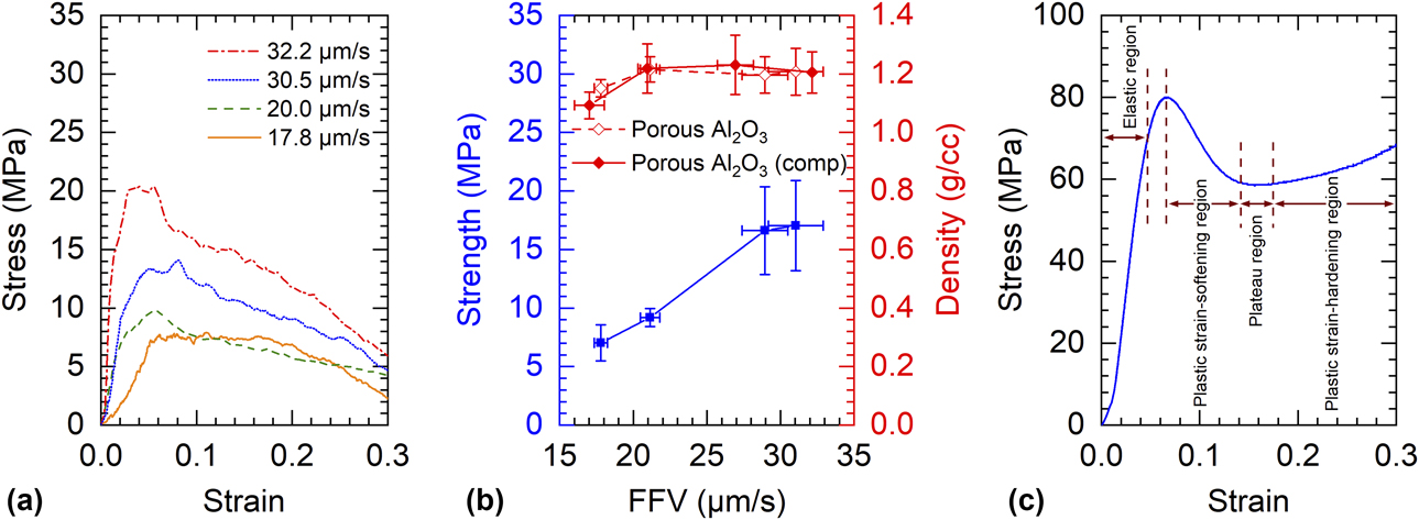
It is expected that compressive mechanical properties of ice-templated porous Al2O3 and pure epoxy would have a governing influence on the compressive behavior of ice-templated composites. Recall that in this work, ice-templated porous Al2O3 materials were processed from aqueous suspensions of same solids loading (20 vol%) but at different FFVs. To understand the effects of FFV on the compressive response of ice-templated porous materials, we processed another set of ice-templated porous Al2O3 materials within the same FFV range (Table I), and Fig. 4(a) shows the representative compressive stress–strain curves (up to 0.3 engineering strain) of the ice-templated Al2O3 materials. All the stress–strain curves feature a linear stress–strain part and a progressive deformation regime in which stress decreased gradually with the increasing strain. Compressive strength is observed to increase with the increasing FFV [Fig. 4(b)]; however, in the high FFV regime further increase of FFV only resulted in a slight increase of strength. We also compared the variation of density of ice-templated Al2O3 materials with FFV to that of the templated Al2O3 materials, which were infiltrated to fabricate ice-templated composites. At comparable FFVs, density values of the porous Al2O3 materials used to fabricate composites are observed to be similar to those of the porous Al2O3 materials utilized to investigate the effects of the FFV on the compressive response. Therefore, we can state that at each FFV regime, the compressive response of ice-templated Al2O3 materials [Fig. 4(a)] represents the compressive response of the templated Al2O3 materials, which were utilized to develop the composites. Figure 4(c) shows the uniaxial compressive response of pure epoxy phase (up to 0.3 engineering strain), which is characterized by a linear stress–strain part (elastic region), plastic strain-softening region, plateau region, and plastic strain-hardening region [Reference Jumahat, Soutis, Jones and Hodzic12]. It can be seen that yield strength of epoxy is about 80 MPa, whereas deformation in the plateau and plastic strain-hardening regions progressed at stress levels well below 80 MPa. Thus, the compressive strength of ice-templated composites is observed to be markedly greater in comparison to the strength of the individual components, i.e., ice-templated porous Al2O3 (12.5 ± 4 MPa) and epoxy (80.3 ± 2 MPa). Therefore, there is an important role and structural advantage of ice-templated morphology in compressive load-bearing and markedly enhancing the compressive mechanical properties of the ice-templated composites relative to that of the individual components.
(a) Representative uniaxial compressive stress–strain curves (up to 0.3 engineering strain) of ice-templated porous Al2O3 materials. (b) Variations of compressive strength and density of ice-templated porous Al2O3 materials with FFV. (c) Uniaxial compressive response of epoxy phase (up to 0.3 engineering strain).

Ice-templated composites processed in this study can be treated as 1–3 diphasic solid [Reference Banda and Ghosh13] in which epoxy phase has connectivity only in a single dimension, where Al2O3 phase has connectivity in three dimensions. In a two-phase composite material, conventionally matrix phase is considered to be the one that constitutes the major volume fraction of composite and has phase connectivity in more than one dimension, which also tends to have a governing influence on the macroscopic mechanical response of composite in comparison to the phase that constitutes minor volume fraction in the composite. In ice-templated composites, volume fractions of Al2O3 and epoxy phases are observed to be in between 0.26–0.37 and 0.63–0.74, respectively. Although the epoxy phase constitutes the major volume fraction, the Al2O3 phase has the three-dimensional connectivity. Therefore, we attempted to provide some insights into the compressive response of ice-templated composite. For compression direction parallel to the ceramic and polymer layers, failure of the ceramic phase will tend to govern the strength of the composite (σc) and we can utilize equal-strain Voigt hypothesis (i.e., the rule of mixtures) to predict strength as [Reference Jumahat, Soutis, Jones and Hodzic12]
 $${\sigma _{\rm{c}}} = {\sigma _{{\rm{epoxy}}}}{V_{{\rm{epoxy}}}} + {\sigma _{{\rm{A}}{{\rm{l}}_{\rm{2}}}{{\rm{O}}_{\rm{3}}}}}{V_{{\rm{A}}{{\rm{l}}_{\rm{2}}}{{\rm{O}}_{\rm{3}}}}}\quad ,$$
σepoxy and  ${\sigma _{{\rm{A}}{{\rm{l}}_{\rm{2}}}{{\rm{O}}_{\rm{3}}}}}$ correspond to the failure strength of epoxy and Al2O3 phases, respectively. Similarly, V epoxy and
 ${V_{{\rm{A}}{{\rm{l}}_{\rm{2}}}{{\rm{O}}_{\rm{3}}}}}$ correspond to the volume fraction of epoxy and Al2O3 phases, respectively.
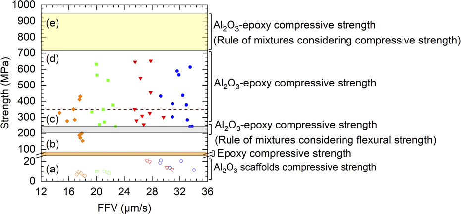
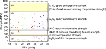
Figure 5 shows the comparison between the measured compressive strength of ice-templated composites and individual components and the calculated compressive strength (σc) of composites based on the rule of mixtures as a function of FFV. For the prediction of σc, we also estimated upper bound (yellow shaded area) and lower bound (gray shaded area) of strength based on the possible mode of failure in ceramic layers. The calculated upper bound of strength is based on the assumption that thin ceramic lamella walls could sustain the applied compressive load and fail axially without experiencing elastic instability (due to buckling) [Reference Porter, Imperio, Wen, Meyers and McKittrick5, Reference Banda and Ghosh13]. For this mode of failure, we considered uniaxial compressive strength of Al2O3 (2.5 GPa) for  ${\sigma _{{\rm{A}}{{\rm{l}}_{\rm{2}}}{{\rm{O}}_{\rm{3}}}}}$ [Reference Munro14]. On the other hand, under compression, thin ceramic lamella walls can undergo bending, resulting in elastic instability within the walls and premature failure of composite. Therefore, to calculate the lower bound of σc, we utilized 3-point bend strength of Al2O3 (510 MPa) for
 ${\sigma _{{\rm{A}}{{\rm{l}}_{\rm{2}}}{{\rm{O}}_{\rm{3}}}}}$ [Reference Bradt, Haselman, Munz, Sakai and Sherchenko15]. For each bound of strength, we also obtained maximum and minimum of compressive strength (σc) based on the composition variation in the ice-templated Al2O3–epoxy composites. A dotted line is used, which approximately separates the specimens that exhibited catastrophic-type failure (above the dotted line) from those that exhibited progressive-type failure (below the dotted line). It can be observed that the measured compressive strength values reside in between the calculated lower bound and upper bound of strength. Moreover, for the composite specimens that exhibited catastrophic-type failure, strength values approach the upper bound of calculated strength. Therefore, Fig. 5 provides some meaningful insights into the compressive deformation behavior of ice-templated Al2O3–epoxy composite materials. Having the measured strength values below the upper bound indicates that, perhaps, pure axial mode of failure is not dominant in ice-templated composites. It can be inferred that presence of epoxy layers in between the adjacent ceramic lamella walls provided a mechanical support to the walls, which must have enhanced the resistance of the walls to elastic instability (i.e., buckling), and therefore the measured failure strength values of the composites are observed to be above the lower bound of strength; however, under compression, lamella walls eventually failed because of elastic instability and as a result upper bound of strength was not achieved. It is possible that if the resistance of the walls to elastic instability increases significantly, compressive failure strength of ice-templated composites could approach the upper bound of strength, which might have occurred in the composite specimens that exhibited failure strength closer to the upper bound of strength.
(a) Compressive strength of ice-templated Al2O3 as a function of FFV; (b) peak stress of pure epoxy under compression; (c) calculated compressive strength of ice-templated composites based on the rule of mixtures, considering failure of ceramic walls due to bending/buckling induced elastic instability; (d) compressive strength of ice-templated composites as function of FFV, dotted line approximately separates the specimens that exhibited catastrophic-type failure (above the line) from the ones that exhibited progressive-type failure (below the line); (e) calculated compressive strength of ice-templated composites based on the rule of mixtures, considering failure of ceramic walls under pure compression.

Uniaxial compressive response at dynamic regime of strain rate
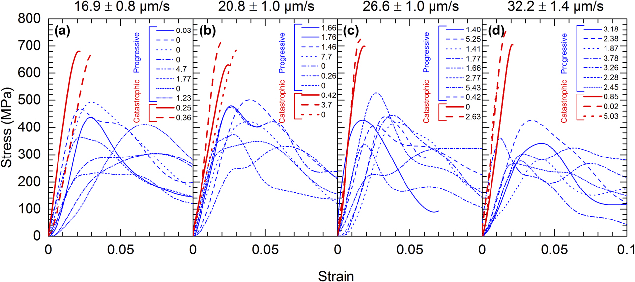
Figure 6 shows uniaxial dynamic (strain rate ≥102 s–1) compressive stress–strain response (up to 0.1 strain) of ice-templated composites. In each figure, the average FFV value corresponds to the unidirectional freezing condition used for the ice-templated Al2O3 materials, which were infiltrated to develop the ice-templated composites. For the split Hopkinson pressure bar (SHPB) experimental conditions used in this study, we achieved compressive strain slightly above 0.1. Dynamic compressive response is observed to be similar to quasistatic compressive response. At each FFV regime, all the composite materials exhibited a linear stress–strain response up to peak stress (σp). Beyond peak stress, composites exhibited either catastrophic-type failure (red curves) or progressive-type failure (blue curves). Also, the dynamic σp values corresponding to the catastrophic-type failure are observed to be significantly greater in comparison to that corresponding to the progressive-type failure.
Uniaxial dynamic (strain rate ≥102 s–1) compressive stress–strain response (up to 0.1 strain) of ice-templated composites processed at average FFV of (a) 16.9 ± 0.8 μm/s, (b) 20.8 ± 1.0 μm/s, (c) 26.6 ± 1.0, and (d) 32.2 ± 1.4 μm/s. The numerical values shown in legend represent porosity (vol%) in composite. The compressive stress–strain curves shown in blue color correspond to progressive-type failure in composites, whereas the stress–strain curves shown in red color correspond to catastrophic-type failure in composites.

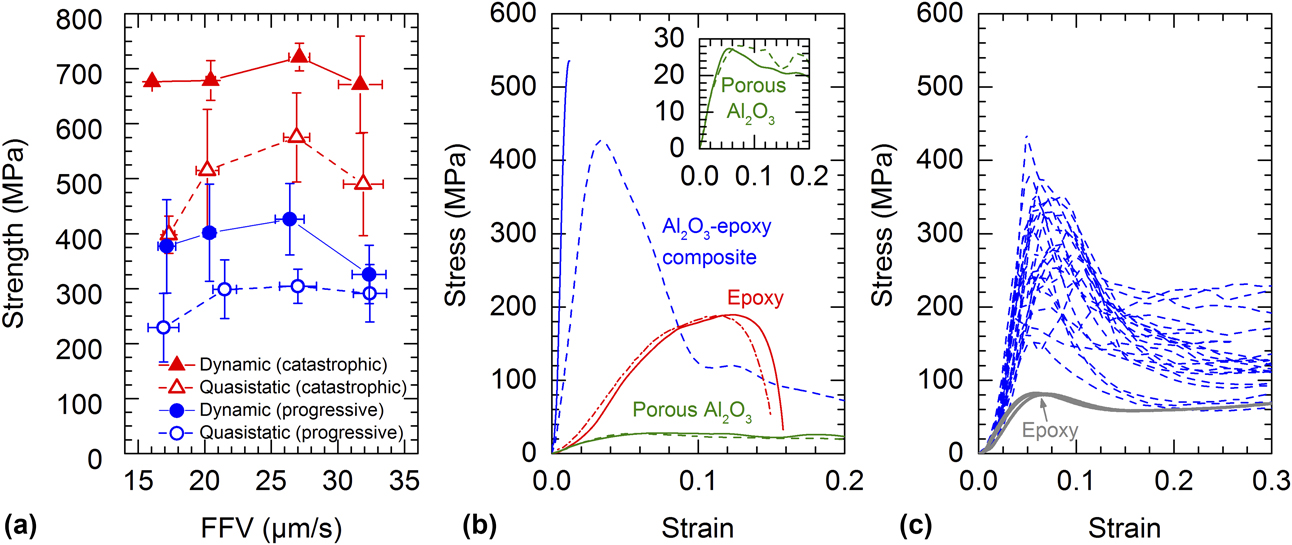
Similar to the quasistatic data, at each FFV regime, we also separated the dynamic σp values into two groups, based on the type of failure, i.e., catastrophic versus progressive. Figure 7(a) shows the variation of average dynamic σp values as a function of average FFV corresponding to catastrophic and progressive failures. For the purpose of comparison, quasistatic σp values are also included. At each FFV regime, dynamic σp corresponding to catastrophic-type failure is observed to be significantly greater in comparison to dynamic σp corresponding to progressive-type failure. Also, for each type of failure, dynamic σp is observed to be considerably greater in comparison to quasistatic σp. For catastrophic-type failure, average dynamic σp values are observed to be in the range of 671–721 MPa, whereas average quasistatic σp values are observed to be in the range of 398–575 MPa. For progressive-type failure, average dynamic σp values are observed to be in the range of 326–426 MPa, whereas average quasistatic σp values are observed to be in the range of 229–304 MPa. Therefore, irrespective of the strain rate regime, ice-templated composites exhibited both catastrophic-type and progressive-type failure. And, irrespective of the type of failure, composites exhibited a pronounced enhancement of strength under dynamic loading in comparison to the quasistatic loading.
(a) Comparison of dynamic and quasistatic compressive strength of ice-templated composites as a function of FFV. For each type of loading condition, the data shown in blue color correspond to progressive-type failure in composites, whereas the data shown in red color correspond to catastrophic-type failure in composites. (b) Representative dynamic compressive response of ice-templated porous Al2O3, epoxy, and ice-templated Al2O3–epoxy composites (corresponding to both catastrophic and progressive types of failure). (c) Quasistatic compressive stress–strain curves of ice-templated composites that exhibited progressive-type failure. Also, included stress–strain response of epoxy phase.

Therefore, the present experimental work revealed that uniaxial compressive mechanical response of ice-templated composites is strain rate sensitive. It is known that uniaxial compressive mechanical response of Al2O3 ceramic and epoxy is strain rate sensitive [Reference Bradt, Haselman, Munz, Sakai and Sherchenko15, Reference Lankford16, Reference Lankford, Predebon, Staehler, Subhash, Pletka and Anderson17, Reference Naik, Shankar, Kavala, Ravikumar, Pothnis and Arya18]. Therefore, it is expected that the rate sensitivity of ice-templated composites could be related to the rate sensitivity of Al2O3 and epoxy phases as well as to the ice-templated morphology. Our recent work [Reference Banda and Ghosh13, Reference Ghosh, Banda, John and Terrones19] revealed that for ice-templated Al2O3 materials processed from 20 vol% Al2O3 suspension (same composition used in this work), dynamic compressive strength was moderately higher relative to quasistatic compressive strength. On the other hand, for ice-templated Al2O3 ceramics with higher ceramic content, compressive strength was observed to be comparable across the quasistatic and dynamic regimes of strain rate [Reference Banda and Ghosh13]. Similar results have been reported for various other cellular solid materials including open-cell and closed-cell aluminum (Al) foams, Al alloy/silicon carbide (SiC) hollow sphere syntactic foams, cp-Al/cenosphere syntactic foams, and amorphous metal foam, in which maximum uniaxial compressive strength did not exhibit any measurable strain rate sensitivity [Reference Deshpande and Fleck20, Reference Wang, Ma, Zhao and Yang21, Reference Luong, Strbik, Hammond, Gupta and Cho22, Reference Schramm, Demetriou, Johnson, Poon, Ravichandran and Rittel23]. One possible rationale is that although the compressive strength of Al2O3 is rate sensitive, in the porosity range of 54–70 vol%, contribution of the Al2O3 phase to the strain rate sensitivity of the compressive response of ice-templated Al2O3 materials could be insignificant [Reference Banda and Ghosh13]. In cellular solids, rate sensitivity can also result from the local dynamic effects because of the rapid crushing of cell walls, which is referred to as microinertia effects [Reference Schramm, Demetriou, Johnson, Poon, Ravichandran and Rittel23, Reference Ghosh, Wiest and Conner24, Reference Tan, Harrigan and Reid25, Reference Tan, Reid, Harrigan, Zou and Li26, Reference Tan, Reid, Harrigan, Zou and Li27, Reference Zhao, Elnasri and Abdennadher28]. These effects can become dominant during two stages of deformation, during the (i) collapse of cell walls at the onset of compressive fracture and (ii) during the progressive deformation in the stress plateau regime. As a result, under dynamic loading conditions, cellular solids can exhibit stress enhancement for failure initiation (peak stress) and/or failure propagation (plateau stress). In the dynamic loading regime, microstructural deformation mechanisms such as bending and buckling of struts and fracture of cell walls are affected by the microinertia effects [Reference Vural and Ravichandran29]. Therefore, it is important to consider the probable role of the microinertia effects in relation to the dynamic response of both ice-templated porous ceramic and ice-templated ceramic–polymer composite.
Under compressive loading, elastic instability due to buckling can cause brittle fracture within the lamella walls of ice-templated ceramic materials [Reference Porter, Imperio, Wen, Meyers and McKittrick5, Reference Banda and Ghosh13]. Dynamic strength enhancement due to microinertia effects can become significant when the asymmetric mode of deformation such as buckling is associated with the deformation process in cellular solids [Reference Vural and Ravichandran29, Reference Reid and Peng30]. It is known that under dynamic loading, lateral inertia of cell walls can suppress the more compliant asymmetric mode of cell deformation and thereby material exhibits a dynamic stress enhancement before the asymmetric mode of deformation is triggered. As a result, microinertia effects can delay the initiation of elastic instability within the lamella walls of ice-templated ceramic and result in an increase of compressive strength (i.e., σp) relative to that under quasistatic loading conditions.
Figure 7(b) shows the representative high-strain rate uniaxial compressive response of ice-templated porous Al2O3, epoxy, and ice-templated Al2O3–epoxy composites (corresponding to both catastrophic-type and progressive-type failure). Dynamic compressive strength of ice-templated composite is observed to be markedly greater than the dynamic strength of both ice-templated porous Al2O3 and epoxy. A comparison of Figs. 4 and 7(b) shows that there is some increase of compressive strength for both porous Al2O3 and epoxy under dynamic loading relative to quasistatic loading. We suggest that under dynamic loading conditions, lamella walls of ice-templated Al2O3 exhibit greater resistance to buckling relative to quasistatic loading and thereby are able to carry a higher amount of compressive load. Moreover, strength enhancement of epoxy in the high-strain rate regime could provide a greater mechanical support to the lamella walls relative to that under quasistatic loading. Although the dynamic strength enhancement of the individual phases (i.e., ice-templated porous Al2O3 and epoxy) could attribute to the dynamic compressive response, it is the ice-templated morphology that provides a greater structural advantage for compressive load-bearing in the high-strain rate regime relative to the quasistatic strain rate regime. As a result, in spite of the marginal strength enhancement in the individual components (porous Al2O3 and epoxy), the dynamic compressive strength of ice-templated composite was markedly enhanced in comparison to quasistatic compressive strength.
On the origin of catastrophic and progressive failure in ice-templated composites
Irrespective of the strain rate regime, ice-templated ceramic–polymer composites exhibited both catastrophic and progressive types of failure. Our results did not suggest any direct correlation between the FFV or porosity and the type of failure. As discussed earlier, for compression direction parallel to the ceramic and polymer layers, failure within the ceramic phase will tend to govern the strength of the composite. Therefore, irrespective of the type of failure, it is expected that brittle fracture in ice-templated ceramic structure will trigger macroscopic failure in the composite. Although brittle fracture in ice-templated ceramic can set the limit for maximum compressive strength in composite, it may not necessarily directly attribute to the contrasting failure behavior, which we observed in the compressive response of the ice-templated composites.
The catastrophic-type failure in ice-templated composite resemblances to the brittle mode of failure, whereas the progressive-type failure can be treated as the ductile mode of failure. For the catastrophic type of failure, during compression, elastic strain energy stored in composite corresponding to peak stress might have been high enough to result in complete loss of compressive load-bearing capacity. Indeed, the composite specimens that exhibited catastrophic-type failure were completely shattered upon reaching the maximum stress. On the other hand, composite specimens that exhibited progressive-type failure were partially intact beyond peak stress and thereby able to maintain the compressive load-bearing capacity to some extent. Figure 7(c) shows the quasistatic compressive stress–strain curves of the ice-templated composite specimens that exhibited progressive-type failure. Included also is the stress–strain response of epoxy phase. It can be observed that during progressive failure stage, deformation in composite proceeded at a stress level that is considerably greater relative to the plateau stress in epoxy. We suggest that in ice-templated composites, progressive deformation stage proceeds by the plastic deformation of epoxy; however, the presence of ice-templated ceramic architecture enhanced the resistance of epoxy to plastic deformation and thereby composites exhibited greater plateau stress relative to epoxy.
Based on the above discussion, it can be argued that the observed progressive type of deformation resulted from a premature, early stage failure in ice-templated composites in contrast to composites that exhibited catastrophic-type failure. At the initiation of failure, stored strain energy might have been insufficient to cause abrupt failure in the composite; however, the stress level was high enough to initiate plastic deformation in the composite. Because the probability of failure in ice-templated composites either by catastrophic or progressive mode was observed to be random, it is possible that mode of failure was governed by the characteristic of damage initiation and propagation. To shed some light into this, we analyzed the fragments of the ice-templated composites corresponding to both catastrophic-type and progressive-type failure.
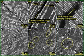
Figure 8 shows SEM images of the composite specimens that exhibited catastrophic-type failure (a–c) and progressive-type failure (d–f). All the images were taken from planes perpendicular to the compressive loading direction (also the ice crystal growth direction). Figure 8(a) shows a low-magnification SEM image of the characteristic of long crack propagation in the ice-templated composite that exhibited catastrophic-type failure, whereas a high-magnification SEM image [Fig. 8(b)] reveals that such cracks propagated along the epoxy–Al2O3 interface. Microstructure analysis further revealed long crack propagation perpendicular to the layers as seen in Fig. 8(c). Similar characteristics of crack propagation were as well observed in the composites that exhibited progressive-type failure [Fig. 8(d)]; however, the microstructural analysis also revealed severely cracked regions (which appear to be epoxy rich) in these composites as indicated in Figs. 8(e) and 8(f) and such damaged regions were readily observable during microscopy. It is to note that such damaged epoxy rich regions were not present in the undeformed composites. Based on these observations, we made the following arguments to rationalize the failure of composites in catastrophic mode and progressive mode.
SEM images of ice-templated composite specimens that exhibited catastrophic-type failure (a–c) and progressive-type failure (d–f). All the images were taken from planes perpendicular to the compressive loading direction (ice growth direction below and above the page).

Irrespective of the type of failure, long cracks along the ceramic–polymer interface and perpendicular to the layers were observed within the fragments of the composite specimens. We suggest that such long cracks ultimately resulted in the fragmentation of the composite specimens and therefore formation of long cracks can be considered as the primary mechanism of axial splitting under compression in ice-templated composites, whereas cracking within the epoxy rich regions limited the load-bearing capacity and initiated early stage failure (i.e., lower peak stress) in the composites that exhibited progressive-type failure response. As the progressive deformation continued, eventually macroscopic crack propagation occurred resulting in the fragmentation of the specimens. In the absence of cracking within the epoxy-rich regions, the composites specimens were able to sustain a greater level of compressive load and as a result catastrophic type of failure occurred at a peak stress level that was significantly greater in comparison to that of the composites that exhibited progressive-type failure. In ice-templated ceramics, all the lamella walls are not perfectly oriented with respect to the ice crystal growth direction [Reference Lichtner, Roussel, Jauffrès, Martin and Bordia31, Reference Arai and Faber32], which could also attribute to the observed modes of failure in ice-templated composites. Perfectly aligned ceramic walls with respect to the loading direction would exhibit resistance to shear, whereas walls misaligned with respect to the loading orientation can undergo local shear failure and cause early stage failure, i.e., lowering peak stress. The composite specimens exhibited both types of failure almost in equal probability. Therefore, it is possible that in the specimens that exhibited progressive-type failure, early stage damage initiation might have triggered by the misalignment of the walls with respect to the loading direction.
Conclusions
This work investigated the compressive mechanical response of ice-templated alumina–epoxy composite materials and studied the effects of strain rate. Ice-templated porous Al2O3 materials were processed from aqueous suspensions of same ceramic content (20 vol%) but over a range of FFV. Microstructural analysis revealed variations of lamella wall thickness and spacing as well as pore characteristics with FFV; however, the overall morphology was observed to be primarily lamellar. Porous Al2O3 materials were infiltrated with epoxy to develop composites.
Although the compressive response measurements of composites suggested some dependence on FFV, more distinct was the differences of stress–strain curves depending on the compressive response beyond peak stress. Ice-templated composites exhibited either a catastrophic-type failure (brittle-like) with a relatively higher peak stress or a progressive-type failure (ductile-like) with a relatively lower peak stress. It was also observed that the failure type was independent of the porosity of both porous ceramic and composite. The compressive mechanical response of the individual components (i.e., ice-templated porous Al2O3 and epoxy) was also studied, which showed that compressive strength of ice-templated composites was markedly greater in comparison to the strength of the individual components. The experimental results were analyzed using the rule of mixtures, which suggested that, perhaps, pure axial mode of failure was not dominant in ice-templated composites, and the presence of epoxy layers in between the adjacent ceramic lamella walls provided a mechanical support to the walls, which enhanced the resistance of the walls to elastic instability (i.e., buckling) and therefore the measured failure strength values of composites were observed to be above the predicted lower bound of strength.
Characteristics of the dynamic compressive response of ice-templated composites were similar to that observed in the quasistatic regime of strain rate; however, for both types of failure, the compressive strength was significantly greater relative to the quasistatic counterpart. Under dynamic loading, lamella walls of ice-templated Al2O3 could have exhibited greater resistance to buckling relative to quasistatic loading and thereby were able to carry a higher amount of compressive load. Moreover, strength enhancement of epoxy in the high-strain rate regime provided a greater mechanical support to the lamella walls relative to that under the quasistatic loading conditions. Overall, ice-templated morphology could have provided a greater structural support for compressive load-bearing in the high-strain rate regime relative to the quasistatic strain rate regime. Finally, some insight was provided into the origin of catastrophic and progressive types of failure in ice-templated composites through the microstructural analysis of the deformed composite specimens.
Methodology
Synthesis of ice-templated porous alumina materials
Ultrafine Al2O3 powder (d 50 = 300 nm, APA-0.5, Sasol, Tuscan, Arizona) was utilized to fabricate the ice-templated porous ceramics, and all the ceramics were processed from aqueous suspensions containing 20 vol% Al2O3 particles. For each aqueous suspension, Al2O3 powder and an anionic dispersant (Darvan C, R.T. Vanderbilt Co., Norwalk, Connecticut) were mixed first in deionized water in a Nalgene bottle, where Darvan C was taken in the proportion of 1 wt% of Al2O3 powder. Next, zirconia (ZrO2) spheres (∼5 mm in diameter) were added to suspension (milling media was taken 4 times by mass of Al2O3 powder) and mixing of the suspension was conducted using a jar mill for 24 h. After completion of the mixing cycle, an organic binder poly(2-ethyl-2-oxazoline) was added to the suspension (5 wt% of Al2O3 powder), and the suspension was milled further for another hour. Afterward, the suspension was sieved to separate the ZrO2 spheres and de-aired in low pressure for 30 min to remove any air bubbles entrapped in suspension.
Unidirectional ice-templating of Al2O3 suspensions was conducted employing a custom-made device. In this device, a Teflon tube is placed on a thin steel plate (referred to as “cold-finger”), filled with an aqueous ceramic suspension, and the entire assembly is inserted inside a liquid nitrogen (N2) Dewar and placed above the surface of liquid N2. The temperature of cold-finger reaches below 0 °C; thus, ice crystals nucleate at the bottom of suspension in contact with cold-finger and grow vertically under the influence of the temperature gradient. The thermally insulating Teflon tube ensures a unidirectional, vertical thermal gradient. By adjusting the distance between the cold-finger and liquid N2, the average unidirectional freezing-front velocity (FFV, i.e., the growth rate) of the ice crystals is controlled. In this study, ice-templating experiments were conducted at four different FFVs, where FFV was determined by dividing the height of a frozen sample with the time required for the completion of solidification [Reference Ghosh, Kang, Banda and Kamaha7]. Frozen samples were of cylindrical form (∼18.5 mm in diameter and ∼20 mm in height) and were freeze-dried at a low pressure (0.014 mbar) and temperature (−50 °C) for 96 h inside a freeze dryer (2.5L, Labconco, Kansas City, Missouri). Freeze-dried samples were sintered at 1550 °C for 4 h in an air atmosphere inside a box furnace (KSL-1700X, MTI Corporation, Richmond, California).
Characterization of ice-templated sintered porous Al2O3 materials: relative density, porosity, and microstructure
Dimension measurements of the sintered materials showed that each ice-templated porous ceramic was about 16.7 mm in diameter and 15.4 mm in height. From each sintered cylinder, a 6 mm × 6 mm × 3 mm specimen was extracted. Mass and dimensions of the sintered porous ceramics were measured to estimate sintered density (ρ*), whereas relative density (ρr) was determined as ρr = ρ*/ρs, where ρs is the bulk density of α-Al2O3 (3.96 g/cm3). Total porosity was estimated using p t = (1 − ρr) × 100. For microstructural characterization, a transverse plane (to the ice growth direction, referred to here as top plane) in each extracted specimen from a height of 8 mm from the bottom of sintered material was utilized and a Phenom ProX tabletop SEM was employed. For each FFV regime, microstructural analyses were conducted for two randomly selected specimens.
Polymer infiltration of ice-templated sintered Al2O3 materials and characterization
Extracted porous Al2O3 specimens were infiltrated with a low-viscosity epoxy resin (EpoxiCure 2, Buehler, Lake Bluff, IL) to develop composites. First, the epoxy resin was thoroughly mixed with a slow curing agent (EpoxiCure 2 Hardener, Buehler, Lake Bluff, IL) and the mixture was subjected to a low pressure (0.1 MPa) inside a vacuum desiccator to any entrapped air bubbles. Next, an extracted Al2O3 specimen was placed in the epoxy-curing agent mixture and infiltration was conducted under low pressure (0.1 MPa) for approximately 30 min. Next, the infiltrated specimen was removed and cured at room temperature for 24 h. These steps were followed to prepare each composite specimen. Here afterward, these infiltrated composites will be referred to as ice-templated Al2O3–epoxy composites or simply ice-templated composites. For comparison purpose, pure epoxy specimens were also prepared. After completion of the curing cycle, surfaces of each composite specimen were carefully ground and polished using 120-, 300-, and 600-grit silicon carbide papers. The density of each composite specimen (ρcomp) was determined from the measurements of mass and dimensions. Relative density of each composite specimen (ρr(comp)) was determined as follows: measured relative density (ρr) of each extracted ceramic specimen (described in Section “Characterization of ice-templated sintered porous Al2O3 materials: relative density, porosity, and microstructure”) was utilized to make the theoretical estimation of the composition (i.e., volume fractions of ceramic and polymer phases) of the corresponding composite sample (assuming 100% infiltration). For example, for a porous Al2O3 specimen of ρr of 0.3, theoretically estimated volume fractions of ceramic and polymer phases will be 0.3 and 0.7, respectively, for the corresponding infiltrated composite (assuming complete infiltration). Next, the theoretical density of the composite (ρcom(cal)) was calculated based on the rule of mixtures. Finally, relative density of composite was estimated using ρr(comp) = ρcomp/ρcomp(cal), and total porosity of the composite was calculated as p t(comp) = (1 − ρr(comp)) × 100.
Measurements of uniaxial compressive response
Uniaxial compressive response of ice-templated composites was characterized both at low- (∼10−3/s) and high-strain rates (≥102/s). For each specimen, 6 × 6 mm cross-section was the loading surface (i.e., compressed parallel to the ice growth direction). A mechanical testing machine (MTS, ALLIANCE RF/300) was utilized for quasistatic compression experiments, using a displacement rate of 0.5 mm/min. On the other hand, a SHPB setup was employed for high-strain rate experiments. The SHPB setup consists of a solid striker bar of length 152.4 mm, a solid incident bar of length 1219.4 mm, and a solid transmission bar of length 914.4 mm; all the bars have a common diameter of 19.05 mm. All the solid bars are made out of high-strength maraging steel. Upon impact by the striker bar, a compressive stress pulse is produced in the incident bar, travels through the bar, and loads the sample in compression. A part of the pulse is transmitted through the specimen to the transmission bar, whereas the rest is reflected back to the incident bar. These stress pulses were utilized to determine the stress–strain response of the composite specimens [Reference Gray33]. For each SHPB experiment, a copper (Cu) pulse shaper was placed at the striker bar–incident bar interface to increase the rise time of the loading pulse and generate a triangular waveform. Stress pulses were measured through the strain gages (mounted in the middle of the incident and transmission bars) using a signal conditioning amplifier (2310B, Vishay, Raleigh, NC) and a high-speed digitizer (NI PCI-5105, National Instrument, Austin, TX). Stress in a specimen was estimated as [Reference Gray33]
 $$\sigma \left( t \right) = E{\varepsilon _{\rm{T}}}\left( t \right){{{A_{\rm{t}}}} \over {{A_{\rm{s}}}}}\quad .$$
In the above equation, E corresponds to the Young’s modulus of the bar material, εT(t) is the time-resolved axial strain in the transmission bar, and A t and A S are the cross-sectional areas of the transmission bar and sample, respectively. Similarly, strain rate in a specimen was estimated as [Reference Gray33]
 $$\dot{\varepsilon }\left( t \right) = - {{2{c_{\rm{o}}}} \over {{l_{\rm{S}}}}}{\varepsilon _{\rm{R}}}\left( t \right)\quad ,$$
where c o is the wave velocity of the bar material, l S is the original length of the specimen, εR(t) is the time-resolved axial strain of the reflected pulse in the incident bar. Strain in a specimen was calculated as [Reference Gray33]
 $$\varepsilon \left( t \right) = \int_0^t {{{\dot{\varepsilon }}_{\rm{R}}}\left( t \right)} \quad .$$
For the purpose of comparison, the uniaxial compressive response of some of the porous Al2O3 materials and pure epoxy specimens were also measured. For both porous ceramic and epoxy, specimens of 6 mm × 6 mm × 3 mm dimensions were utilized (6 × 6 mm cross-section being the loading direction). Because the porous ceramics and epoxy have low strength and modulus, a modified SHPB setup was employed to measure the compressive response. This modified setup is made of high-strength aluminum (Al) alloy and consists of a solid striker bar of length 330.2 mm, a solid incident bar of length 1524 mm, and a solid transmission bar of length 914.4 mm; all the solids bars have a common diameter of 12.7 mm.