


I. INTRODUCTION
Linear monopole arrays are extensively used in many antenna systems due to their simplicity, low cost, polarization purity, reasonable bandwidth, and power-handling capability [Reference Tomasic and Hessel1]. However, the strong mutual coupling between neighbored antenna elements also results in radiation patterns and matching degradations. The feed network can also be directly affected. It has been theoretically demonstrated that mutual coupling effects on radiation patterns can be reduced with appropriate loads [Reference Pozar2–Reference Mailloux5]. Recent studies [Reference Lau, Ow, Kristensson and Molisch6] have shown that correlation and capacity of coupled antennas in multiple-input multiple-output (MIMO) systems can be greatly improved by introducing proper matching loads into the multiple-antenna system.
The aim of this paper is to design a linear array of 12 monopoles by considering the coupling. Moreover, the antenna design must be robust and easy to manufacture in order to be integrated on a vehicle roof, and thus, to undergo outdoor conditions such as rain and wind. A typical application of such an antenna might be a HyperLAN2 telecommunication scenario between transit vehicles and base stations to operate data transfer between 5.47 and 5.72 GHz. Besides these objectives, an evolution of this antenna to add beam scan functionalities might be investigated to increase its versatility for this kind of applications. That is why an antenna array has been preferred to other radiating devices such as Yagi-Uda or horn antennas. This work is an extension of a previous design presented in [Reference Sayed Ahmad, Thevenot, Koubessi, Arnaud and Monediere7].
Section II describes how to simultaneously realize an objective radiation pattern and the best matching of the monopole array and its feed network by including the different couplings. A brief reminder of the global synthesis method from [Reference Drouet8] is given. Section III deals with the design and performances of the monopole array and its feed network. A comparison to a design where the couplings are ignored is also investigated to emphasize the improvement. The manufactured prototype and its measurement results are then presented.
II. GLOBAL SYNTHESIS METHOD
The antenna array is composed of 12 monopoles with their feed network. The strong interactions between the monopoles involve an accurate feed network design to maximize the directivity.
The objective consists in the determination of the impedance matching and the incident power to reach both the objective radiation pattern and the best matching for the monopole array.
A theoretical method based on the synthesis of multi-feed electromagnetic band gap (EBG) antennas with strong couplings is applied for this monopole array design. It has been previously described in [Reference Drouet8]. The different steps can be summarized as follows.
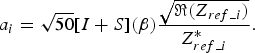
At first, the S matrix and the radiation patterns of the 12 monopoles on a finite ground plane are computed by means of CST Microwave Studio. These different patterns, ϕ i (1 ≤ i ≤ 12), are obtained by successively feeding each monopole to include the coupling effects when they are neighbored. Other monopoles are loaded on fixed impedances that are stored for the synthesis process. Then, the patterns are used to define the β i coefficients that correspond to the best linear combination to reach the objective radiation pattern ϕ obj, as expressed by equation (1). In other terms, they represent the weights that must be applied to the radiation pattern of each of the 12 monopoles. The objective radiation pattern is defined in equation (2) as the product of one-monopole radiation pattern ϕ monopole by the array factor. In this relation, d relates to the distance between each monopole and φ i denotes the phase shift at the ith monopole. It can be noted that this objective pattern can also be defined arbitrarily with specific constraints on the side-lobe level or the main-beam shaping. As a whole, ϕ monopole can refer to a theoretical radiation pattern and is different from ϕ i. At last, equation (3) leads to the antenna impedances considered as a reference (Z ref_i) to reach the matching and equation (4) gives the input waves a i that the feed network must achieve. The reader can refer to [Reference Drouet8] for more details on this synthesis method.


III. DESIGN OF THE ANTENNA ARRAY
This section describes the monopole array design for the HyperLAN2 bandwidth (5.47–5.72 GHz).
In order to avoid grating lobes and to obtain a radiation pattern in the array alignment, the space between two nearby monopoles must stay lower than 0.5λ 0, which is why a 0.45λ 0 (24.12 mm) has been chosen for our design. The 12 monopoles are fasten to a finite ground plane whose dimensions are L x = 100 mm and L y = 330 mm, as mentioned in Fig. 1. Each monopole is 2.53 mm in diameter. The connections between the monopoles and the feed network ports are made of 50 Ω coaxial transitions that are drilled through the ground plane as can be seen in Fig. 2. The feed network is printed at the rear of the antenna ground plane, onto a 0.508 mm thickness Duroid 6002 substrate (εr = 2.94, tg δ = 0.0012).
Array of 12 monopoles designed with CST Mws separated by 0.45λ, and feed distribution network designed with Agilent ADS.

Monopoles are fed by a coaxial guide drilled through the ground plane.

The different steps of the design are now summarized:
1) First, the objective radiation pattern is set to obtain the main lobe in the direction θ = 75°. The array factor is deducted from equation (2) by applying equation (5). It allows setting the objective radiation pattern ϕ obj of Fig. 3, which corresponds to the product of this array factor by the monopole radiation pattern. It should be noted that this result is approximated because the analysis considers that monopoles do not interfere with each other. However, it does not matter because the aim is only to define a goal function as in a classical synthesis procedure.
(5)
2) Next, a full-wave simulation of the monopole array is performed to obtain the global scattering matrix [S] and the radiation patterns ϕ i. This study shows that the couplings between monopoles could reach −12 dB in the worst cases. The weights β i are then deducted according to equation (1) and reported in Table 1. Figure 3 points out the similarity between the objective radiation pattern and the linear combination of the neighbored monopole radiation patterns affected by the coefficients β i.
3) Finally, the optimum weights a i and the input impedances Z ref_i, which simultaneously perform the objective radiation pattern and the matching of all the feeding ports, are calculated using equations (3) and (4), the [S] matrix, and the β i vector. These values are given in Table 1 (columns 4 and 5) with the optimized monopole lengths. These have been set to comply with the different impedance values resulting from the synthesis procedure and to minimize the feed distribution network complexity.
4) The feed network has been designed with the Agilent ADS software to perform the weights and the impedance matching specified in Table 1. The corresponding layout is shown in Fig. 2. The last step consists in the co-simulation of the whole antenna (monopoles and feed network together) in CST Design Studio. The Agilent ADS layout is connected to the CST MWS simulation by Touchstone files including the S parameters of the feed network. Thus, this full-structure simulation provides the performances of the whole antenna array with the synthesized feed network. The radiation patterns, gain, return loss, and dielectric losses are computed. The comparison of the synthesized radiation pattern obtained by this simulation is compared with the theoretical linear combination in Fig. 4. The gain and dielectric losses are evaluated in Fig. 5.

Comparison of the objective radiation pattern (radiation pattern of monopole *array factor) with the linear combination of the radiation patterns of monopoles (f = 5.6 GHz).

Agreement of the synthesized radiation pattern with couplings and theoretical linear combination of the monopole patterns at 5.60 GHz. Resulting radiation pattern with couplings neglected is also presented to show the interest of including couplings in the design method.

Left: simulated gain in the direction θ = 75° (left plot) and dielectric losses for the entire structure simulation (right plot) over the frequency range.

Normalized incident waves and reference impedances that optimize the antenna array performances for a specified radiation pattern (5.60 GHz). Values are given for two cases: couplings included or neglected.

In order to prove the interest of the design method described in this paper, a classical design neglecting the couplings has been made for comparison. As a whole, the S matrix in equation (3) has been simplified with the relations given in equation (6) to obtain the S″ matrix.

The new values for Z ref_i and a i are determined using equations (3) and (4), whereas β i stays unchanged. The corresponding values are given in Table 1. Another feed network has been designed to find the incident waves (sixth column) that agree with the objectives a i (the last column).
Then, the effect of coupling has been evaluated in Fig. 4 presenting the antenna radiation pattern at 5.6 GHz. The results show that the directivity is 2 dB lower when the couplings are neglected.
By observing the coupling between monopoles in Fig. 6, the corresponding values can reach −12.5 dB in worst cases. It leads directly to strong interactions between monopoles that dramatically affect the antenna array performances and the matching as can be seen in Fig. 7.
Example of S″ij parameters of the monopole array showing the strong couplings.

Example of S″ii parameters of the monopole array showing a poor matching without the synthesis procedure.

The interest to carefully design the feed network, as in Section III, is now clearly demonstrated.
Values are given for two cases: couplings included or neglected.
IV. MEASURES
The monopole array and the feed distribution network were manufactured as can be seen in Fig. 8. The feed network is glued at the rear of the ground plane and screws were added to secure the radiofrequency (RF) contacts. Interactions between the screws and the circuit have been checked and considered as insignificant. An SubMiniature version A (SMA) connector is used to feed the array.
Photograph of the monopole array and its feed network.

The measurements were achieved in the laboratory anechoic chamber between 5.47 and 5.72 GHz and have been compared with simulation. The antenna return loss depicted in Fig. 9 shows that values better than −15 dB are obtained on |S 11|. A slight discrepancy of 50 MHz can be observed compared to the simulation, but it represents only 0.9% of frequency shift that can be due to the mesh accuracy during simulation or manufacture tolerance. The radiation patterns are then compared at 5.6 GHz in the array yz-plane. The measured gain and pattern of Fig. 10 agree well with the prediction. The difference between the simulated and the measured gain over the frequency range is lower than 0.5 dB. Metallic losses in the feed network and the measurement accuracy of the anechoic chamber (±0.5 dB) can be responsible for this variation. This realization allows concluding that the synthesized design is reliable and that the global synthesis method detailed in [Reference Drouet8] for EBG can be derived for classical antenna design with couplings. The impedance matching and the objective radiation pattern performances are correctly maximized through the synthesis design.
S11 comparison between simulation and manufactured prototype.

Comparison of the simulated radiation pattern and measurement at f = 5.6 GHz.

V. CONCLUSION
In this paper, a monopole linear array has been designed and manufactured. In such a structure the monopoles strongly interact with each other. It is demonstrated that if no care is taken, the intensity of the coupled waves may damage the functioning of a feed network.
In our study, the feed network has been designed to deal with the couplings by considering the impedances and the input waves that optimize the antenna performances.
The feed network and the monopoles array were manufactured. The whole antenna was successfully tested. The experimental radiation pattern and return loss are very close to the simulation. Such an antenna is robust and can be optimized with the described method to satisfy specific applications that need an antenna on a vehicle roof for data transfer. As the method takes into account couplings, a particular beam pointing with reduced or controlled side lobes can be achieved easily. As further works, this method can be extended to an active monopole array to provide efficient beam scan capabilities.
 A. El Sayed Ahmad was born in Tripoli, Lebanon in 1984. He received the M.S. degree in high frequency telecommunications from University of Limoges, France, in 2007. He received his Ph.D. degree in Telecommunications from the XLIM research laboratory, University of Limoges, in 2010. Then, he got a post-doctoral position in INSA (Institut National des Sciences Appliquées), Rennes, France. His main research interests are synthesis of array of coupled antennas and design of broadband antenna array.
 Marc Thévenot was born in Limoges, France, in February 1971. He received the BS and M.Sc degrees in Microwaves from the University of Limoges, France, in 1995. He received his Ph.D. degree in Electronic from the University of Limoges in 1999. He joined the CNRS in 2001. His current research interests are in microwave electromagnetism. These studies are applied to the antenna domain and the EBG materials for microwave. He is also in charge of the multifunction antenna activities of the Wave and Associated Systems department of the XLIM laboratory.
 Cyrille Menudier was born in Limoges, France, in 1981. He received the M.S. degree in high frequency telecommunications from University of Limoges and the engineering diploma from ENSIL in electronic engineering in 2004. He received his Ph.D. degree in Telecommunications from the XLIM research laboratory, University of Limoges, in 2007. Then, he got a post-doctoral position in CNES (French Space Agency) until 2009 where he worked on reconfigurable reflectarray antenna. He is currently working in the Wave and Associated Systems department of the XLIM research laboratory. His research interests include reflector antenna, reconfigurable antenna, reflectarray and mutual couplings effects.
 Majed Koubeissi was born in Saida, Lebanon, in 1979. He received the B.S. degree in Telecommunication and Networks from Lebanese University, Saida, Lebanon, in 2001 and the degree of High Frequency Electronics Engineering from the ENSIL School, Limoges, France in 2004. He received the Ph.D. degree in Telecommunications from the XLIM research laboratory, University of Limoges, France in 2007. Since 2007, he has been a R&D engineer at the Wave and Associated Systems department of the XLIM laboratory. His research interests include phased arrays, beamforming networks, multiband antennas, DRAs and circular polarized antennas.
 Eric Arnaud was born in France in 1970. He received the Diplôme D'Etudes Supérieures Specialisées (DESS) and Ph.D. degrees in electronic and telecommunication from the University of Limoges in 1994 and 2010, respectively. He did his Ph.D. on circularly polarized EBG antenna. From 1996 to 2001, he has been Microwave responsible of Free-Electron Laser (L.U.R.E laboratory). Since 2001, he has been in charge of XLIM laboratory antenna test range and he participated to several research projects related to design, development and characterization of antennas. His research interests are mainly in the fields of circularly polarized EBG antenna and realization of antennas through ink-jetting of conductive inks on RF substrates.
 Thierry Monediere was born in 1964 in Tulle (France). He obtained is Ph.D. in 1990 in the IRCOM Laboratory of the University of Limoges. He is actually Professor in the University of Limoges and he develops his research activities in the XLIM Laboratory. He works on multifunction antennas, EBG antennas and also active antennas. He is also in charge of the Wave and Associated Systems department of the XLIM laboratory.



