I. INTRODUCTION
316L stainless steel is a promising material for application in reactor vessels and piping systems in nuclear power plants owing to a good combination of its excellent creep strength, corrosion resistance, and high sensitization resistance. Reference Hong, Lee and Byun1 Generally, the service temperature range for 316L stainless steel is from 450 to 600 °C, which is right in the regime of its dynamic strain aging (DSA) effect. Reference Jiang, Chen, Fan, Dong, Jiang and Lu2
DSA, which depends on strain rate and temperature, is the phenomenon of interactions between diffusing solute atoms and mobile dislocations during plastic deformation. DSA is manifested as serrations on a stress–strain curve, which is one of the most prominent examples of plastic instabilities known as serrated yielding (Portevin-Le Chatelier effect). Reference Portevin and Le Chatelier3 Scholars worldwide have paid more attention to the essence and occurrence condition of DSA and proposed different physical models, for example, Cottrell model, Reference Cottrell4 McComick model, Reference McCormick5 and Van den Beukel model. Reference Van den Beukel6 These models have held that the serrated flow results from the repeated pinning and unpinning of mobile dislocations with the presence of solute atoms. Schoeck et al. Reference Schoeck7 further extended the original DSA theory by referring the collective behavior of dislocations. Considering the integral behavior of dislocations and the interaction between solute atoms and dislocations, Xiao et al. Reference Xiao, Li and Qian8 proposed a physical model to determinate the critical strain corresponding to the appearance and disappearance of serration and discussed the strain rate-temperature ranges when serration occurred.
Recently, some studies have been conducted on DSA for stainless steel. The results showed that the dislocation structure of austenitic stainless steels involving 316L(N) stainless steel transited from a cell structure below 200 °C to a planar one between 200 and 550 °C and returned to a cell or subgrain structure beyond 550 °C. Reference Kanazawa, Yamaguchi and Nishijima9–Reference Srinivasan, Valsan, Sandhya, Bhanu Sankara Rao, Mannan and Sastry11 Hong et al. Reference Hong, Lee and Lee12 characterized the fatigue deformation of 316L stainless steel at elevated temperature and concluded that DSA caused a reduction in fatigue life. Jiang et al. Reference Jiang, Chen, Fan, Dong, Jiang and Lu13 investigated the effect of DSA pretreatment on creep-fatigue behavior for 316L stainless steel. It was found that DSA was a macroscopic phenomenon due to a displacement or mean strain abrupt jumping during the cyclic deformation for stress controlled fatigue tests. Sarkar et al. Reference Sarkar, Nagesha, Sandhya and Mathew14 observed an anomalous temperature dependence of strain accumulation in the DSA regime by ratcheting tests for 316LN stainless steel. Choudhary Reference Choudhary15 performed a series of tensile tests for 316L(N) austenitic stainless steel in a wide range of strain rates and temperatures, and observed the serrated flow behavior in the tests. To indicate the type of atom in DSA, Choudhary calculated the average activation energy by four methods, including a strain rate-1/temperature map, an intercept method, and two critical strain methods.
DSA under monotonic tensile loading conditions has been well studied. However, there are rare studies on the evolution of DSA during cyclic loading. In this study, low cycle fatigue (LCF) tests were carried out for 316L stainless steel at 20 and 600 °C, respectively. The cyclic deformation behaviors at different strain ranges and temperatures are discussed. The analyses focus on the characteristic of DSA and the relationship between the DSA and the cycle numbers. Finally, the crack nucleation and propagation characteristics at 600 °C are discussed from SEM observations on fracture surfaces.
II. EXPERIMENTAL PROCEDURE
Test material used in this study was 316L austenitic stainless steel, solution treated at 1353 K. The chemical composition of the material is shown in Table I. Yield stress of the material at room temperature was 247 MPa, ultimate tensile stress 564 MPa, Young modulus 200 GPa, and Poisson's ratio 0.3.
Chemical composition of specimen for 316L (wt%).

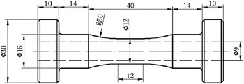
Hollow cylinder tube specimens were used in uniaxial LCF tests and the shape and dimensions of the specimen are shown in Fig. 1. The specimen has 12 mm outside diameter, 9 mm inside diameter, 12 mm gage length, and 1.5 mm wall thickness. A tension–torsion electric–hydraulic servo LCF machine was used for strain controlled uniaxial LCF tests at 20 and 600 °C. Mises strain range was set to 0.7, 1.0, and 1.2% in all the tests at a Mises strain rates of 0.1% s−1. The high frequency induction heating equipment is used to attain 600 °C. The temperature fluctuation in the gauge is kept within 3 °C. The number of cycles to failure was defined as the number of cycles of 25% axial stress amplitude drop from that at half-life.
Shape and dimensions of the specimen.

III. EXPERIMENTAL RESULTS AND DISCUSSION
A. Hysteresis loop properties
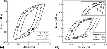
Hysteresis loops at half-life for different strain ranges and temperatures are shown in Fig. 2. The stress is increased with the increase of strain range at both 20 and 600 °C. The hysteresis loops are smooth without any serrations for all three strain ranges at 20 °C, while the serrated flow, called the Portevin-Le Chatelier effect, can be observed at 600 °C. This difference between 20 and 600 °C is generally attributed to DSA. Reference Portevin and Le Chatelier3,Reference Gupta, Singh, Reddy and Hariharan16 Essentially, DSA results from the attractive interaction between solute atoms and mobile dislocations. At lower temperature (20 °C), DSA mainly depends on the diffusion of solute atoms. The effects from the density and diffusion rate of mobile dislocations can be neglected.
Hysteresis loops at half-life: (a) 20°C, (b) 600°C.

At 20 °C, the diffusion velocity of solute atoms is so slow that the effective atmosphere around the arrested dislocations cannot be formed and the pinning to the dislocation cannot occur, even at larger strain range. At 600 °C, however, the diffusing velocity of solute atoms is larger enough. When the dislocation movement is limited by the obstacles, there are sufficient solute atoms segregating to the arrested mobile dislocations.
The mobile dislocation is pinned by the effective solute atom atmosphere and the rapid stress increase can be observed from the hysteresis loops, Fig. 2. Subsequently, unpinning will occur since the dislocation gets rid of the solute atom atmosphere by the external force and the stress can be reduced. The DSA effect is a repetition of pinning and unpinning and the stress serrations can be seen from the hysteresis loops.
To reflect the pinning effect of the solute atoms on mobile dislocations, the parameter “stress drop”, which is calculated from the highest points to lowest points of a stress serration at half-life, has been introduced to characterize the degree of serrated yielding for different strain ranges. Reference Pham and Holdsworth17 The maximum stress drop corresponding to Δε = 0.7, 1.0, and 1.2% are 10.4, 1.5, and 5.4 MPa, respectively. The comparison of the maximum stress drops for different strain ranges indicates that DSA is most significant at Δε = 0.7% and weakest at Δε = 1.0%. DSA is thought to be associated with the interaction between solute atoms and mobile dislocations, while the diffusion of solute atoms is strongly affected by the vacancy concentration. Reference McCormick5 The dependence of vacancy concentration C v on strain range Δε can be expressed as
 $${C_{\rm{v}}} = K{\left( {{{\Delta \varepsilon } \mathord{\left/ {\vphantom {{\Delta \varepsilon } 2}} \right. \kern-\nulldelimiterspace} 2}} \right)^m}\quad ,$$
where K and m are constants. As shown in Eq. (1), C v ∝ (Δε/2) m , vacancy concentration increases with the increase of strain range.
The highest trend for serrated flow occurring at Δε = 0.7% may be attributed to the most effective interaction between solute atoms and dislocations. At Δε = 0.7%, there are more solute atoms segregating to the surrounding of the arrested mobile dislocations due to the most favorable combination of the velocity of mobile dislocations and the mobility of solute atoms. Therefore, more significant DSA can be shown.
At Δε = 1.0%, the vacancy concentration increases more sharply than at Δε = 0.7%. The diffusion of solute atoms becomes easier and the velocity of solute atoms is higher than those of dislocations mobility. Consequently, the mobile dislocations drag the solute atoms and cannot be unpinned from solute atoms. Thus, the slight stress reduction and weakening DSA occur.
New microstructural features are developed at Δε = 1.2% and more DSA mechanisms become active. In addition, the collective behavior of dislocations, which is actually the interaction of a large number of co-occurring dislocations, without requiring the diffusion of solute atoms, Reference Chen, Wang, Wu, Liu, Stoica, Wu and Liaw18 should be considered so as to understand the serrated flow at Δε = 1.2%. At Δε = 1.2%, DSA is believed to be associated with the interaction between solute atoms and mobile dislocations as well as the collective behavior of dislocations.
B. Cyclic stress response
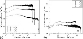
The relationships of peak stress with the number of cycles at Δε = 0.7, 1.0, and 1.2% for two temperatures are depicted in Fig. 3. The stress response at 20 °C can be characterized by three stages [Fig. 3(a)]. In stage I, the cyclic hardening occurs and peak stress is maximized after the first few cycles between about cycle 1st and 20th. In stage II, the cyclic softening occurs from the maximum peak stress to the macro-crack initiation and the peak stress is reduced. In stage III, the peak stress is gradually reduced due to propagation of macro-cracks. At 600 °C, the material exhibits similar hardening–softening modes at strain ranges 0.7 and 1.0% [Fig. 3(b)]. In contrast, at the strain range 1.2%, after a gradual softening, the material shows a noticeable secondary hardening until the final load drop. To describe the amounts of cyclic hardening and cyclic softening during LCF deformation, we introduce two parameters “hardening ratio” and “softening ratio” defined as Eqs. (2) and (3), respectively.
 $${R_{\rm{H}}} = {{{\sigma _{{\rm{max}}}}} \over {{\sigma _{{\rm{max}}\left( 1 \right)}}}} - 1\quad ,$$
 $${R_{\rm{s}}} = 1 - {{{\sigma _{{\rm{max}}\left( {{{{N_{\rm{f}}}} \mathord{\left/ {\vphantom {{{N_{\rm{f}}}} 2}} \right. \kern-\nulldelimiterspace} 2}} \right)}}} \over {{\sigma _{{\rm{max}}}}}}\quad ,$$
where σmax, σmax(1), and
 $\sigma _{{\rm{max}}\left( {{{N_{\rm{f}} } \mathord{\left/ {\vphantom {{N_{\rm{f}} } 2}} \right. \kern-\nulldelimiterspace} 2}} \right)}$
represents the maximum peak stress, the initial peak stress, and the peak stress at half-life, respectively.
Cycle deformation response of 316L stainless steel: (a) 20°C, (b) 600°C.

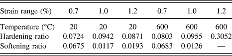
The hardening ratio and the softening ratio calculated from tests are listed in Table II. At Δε = 0.7% or 1.0%, neither parameter is much different between 20 and 600 °C. At Δε = 1.2%, however, the hardening ratio at 600 °C is prominently higher than that at 20 °C and a pronounced secondary hardening occurs before fatigue failure. In the DSA regime, the cyclic properties of materials are affected by DSA. During the early stage of cycles, the dislocation cross-slip is effectively restricted by DSA, so that the dislocation glide can only be observed on particular planes. With formation increasing, the planar structures will obstacle the dislocation movement. Thus, the material suffers from the hardening effect. The dislocation density at 600 °C is also higher than that at 20 °C due to the effective pinning by the solute atom atmosphere.
Hardening ratio and softening ratio for different strain ranges.

Note: “—” means that the softening rate can't be calculated by Eq. (2) because of the influence of secondary hardening.
All these results indicate that the initial cyclic hardening is governed by two processes: the hardening from the planarity structure and the higher immobile dislocation density in DSA. Therefore, at 600 °C, the material shows a larger hardening ratio at Δε = 0.7%. The weakest DSA effect occurs at Δε = 1.0% and the maximum stress drop is only 1.5 MPa. The hardening ratio is similar to that at 20 °C. At 600 °C, in the strain range 1.2%, there is a significant increase in density and incidence of dislocation multiplication and pile-up in the glide band. The evident stress serration is observed and the material shows a higher hardening ratio for the early stage.
However, a temperature rise will accelerate the dislocation annihilation and result in an earlier softening and a higher softening rate. Reference Chai and Andersson19,Reference Hong, Samson and Lee20 When DSA occurs, the additional dislocations will be generated to hold an imposed strain rate and reduce the dislocation annihilation rate. When the softening amount produced by dislocation annihilation at 600 °C is close to the hardening amount produced by DSA, the softening ratios are almost the same as those at 20 °C for Δε = 0.7 and 1.0%. The secondary hardening may be responsible for the hardening amount by DSA, which is stronger than the softening amount by dislocation annihilation. The secondary hardening behaviors in the regime of DSA for LCF have already been reported for 316LN stainless steel, Reference Prasad Reddy, Sandhya, Mathew and Sankaran21 Z2CND18.12N stainless steel. Reference Yu, Yu, Chen, Jin and Chen22
C. Maximum stress drop with number of cycles
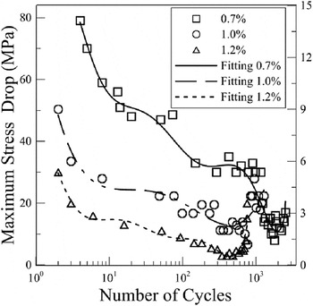
The maximum stress drops at different strain ranges are plotted with respect to the number of cycles in Fig. 4. It should be noted that the right Y-axis can be used for Δε = 1.0% due to the lower stress drop. The maximum stress drop is most active first and decreases gradually for all strain ranges. The maximum stress drop becomes reactivated after a few more cycles, as a result from the strengthened pinning effect between solute atoms and dislocations. The materials possess a high initial dislocation density during the primary cyclic deformation and the velocities of mobile dislocation can be reduced. Therefore, it is easy to gain the pinning between the slow moving dislocations and solute atoms.
Relationship between the maximum stress drop and number of cycles.

On the other hand, since 316L stainless steel possesses a face-centered cubic (FCC) structure with low stacking fault energy, solute atoms can segregate to stacking fault areas to form Suzuki atmospheres. Obvious serrate yield can be observed in primary cycles because the pinning effect of solute atoms on dislocations is further strengthened by the Suzuki atmospheres. The cyclic softening is exhibited after the initial hardening, i.e., the reduction of peak stress. The stress drop and the serration amount in hysteresis loops both decrease gradually during the cyclic softening stage, since the pinned dislocations cannot separate from the solute atom atmospheres, due to the smaller imposed force. Almost there is no stress serration in the softening stage for Δε = 1.0%.
The solute atom density around the arrested dislocations is increased due to the formation of Snoek atmospheres before fatigue failure and the pinning effect of solute atoms on the arrested dislocations can be further strengthened. The DSA effect is enhanced again. The corduroy structure, which acts as an obstacle to the dislocation movement, is formed before fatigue failure. Reference Pham and Holdsworth17 The pinning time that the solute atoms diffuse to the mobile dislocation is shortened and the DSA effect occurs again. Consequently, besides the types of the solute atom atmospheres, the corduroy structure is also responsible for the re-occurrence of the stress serration before fatigue failure.
The decline rate of fatigue life δ has be defined to consider the effect of DSA on the fatigue life, as follows
 $$\delta = 1 - {{{N_{{\rm{HTf}}}}} \over {{N_{{\rm{RTf}}}}}}\quad ,$$
where, N HTf and N RTf are the fatigue life at high temperature and room temperature (20 °C), respectively. δ can be calculated based on the test results and the values are 91.4% for strain range 0.7%, 82.4% for 1.0%, and 84.6% for 1.2%, respectively. It can be seen that the decline rate of fatigue life is increased with the increase of maximum stress drop. When DSA occurs, the external stress can be increased to overcome the atom atmospheres pinning. Thus, the stress concentration is more significant at the crack tip and the crack propagation can be accelerated until fatigue failure.
D. DSA in different number of cycles
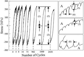
The hysteresis loops with cyclic deformation response for Δε = 0.7% are presented in Fig. 5. During the early stages, the serrated yielding is more intense in the loading stage [(1), (3)] than in the unloading stage [(2), (4)] within one cycle, as indicated by the comparison of stress drop amplitude. At the cycle 5th, the maximum stress drop during the loading stage is almost four times larger than that during the unloading stage. The DSA effect is more significant during the loading stage.
Hysteresis loops of different cycles for △ε=0.7%.

Interestingly, the activities of serration flow stress are different between the tensile loading stage and the compressive loading stage. This difference can be characterized by the maximum stress drop [(5)] and single serration length (6), a period between a valley and the previous valley, which are both larger at the compressive loading stage than those at the tensile loading stage. The degree of serrated yielding is dependent on the number of cycles. From the cycle 4th to 13th, there is more serration and the longer serration is observed. The DSA occurs in all stages within any cycle. After the cycle 13th, the DSA effect becomes weaker. Specifically, from the cycle 14th to 73rd, some serrations vanish during the unloading stage from ε = 0.35% to ε = 0.10%. From the cycle 74th to 902th, the activity of stress serration is only observed at the compressive loading stage. From the cycle 903th to 2280th, the DSA effect disappears and the hysteresis loops become smooth. Finally, the flow serration reoccurs before the fatigue failure.
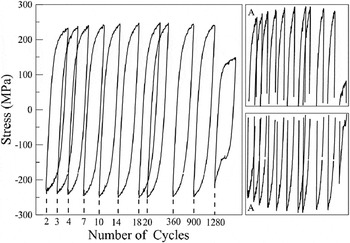
As showed in the hysteresis loops at Δε = 1.0% (Fig. 6), a lower stress drop occurs for any cycle in the process. However, the feature is still obvious that stress serrations during the first four cycles are the most active and then gradually disappear, no DSA up to the cycle 550th. The stress serration reoccurs before final failure.
Hysteresis loops of different cycles for △ε=1.0%.

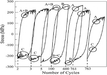
Although the serrations are very active at first five cycles for Δε = 1.2%, the intense stress serration only occurs during the tensile and compressive loading stages. The stress drop and serration length are smaller compared with the results of the strain range 0.7%. The activity of stress serration is gradually attenuated until the cycle 130th and then the serrated yielding is almost unchanged from the cycle 130th to 600th. However, the serration quantity increases significantly from the cycle 600th to failure (Fig. 7).
Hysteresis loops of different cycles for △ε=1.2%.

Rodriguez Reference Rodriguez23 summarized three types of serrations (Types A, B, and C) according to their characteristics on the stress–strain curves. In the present study, serrations at Δε = 0.7 and 1.0% seemly belong to Type A, since they are periodic and characterized by an abrupt rise as well as a drop below the general level of the stress–strain curve (Figs. 5 and 6). At Δε = 1.2%, however, the type of serrations varies depending on the cycle. During the tensile loading of the first five cycles, Type A and Type B are also observed: Type A + B and type B fluctuates near the mean stress in quick succession. During the compressive loading, the stress drop lies over the smooth hysteresis loops due to dislocation unpinning and the serration can be considered as Type C. However, from the cycle 100th to 300th, Type B occurs during the tensile loading and Type B + C is observed during the compressive loading. Type A and C appear before the fatigue failure. In general, the types of serrations depend on the number of cycles at Δε = 1.2%. Similar conclusions were also obtained by Sudhakar Rao et al. Reference Sudhakar Rao, Chakravartty, Nudurupati, Mahobia, Chattopadhyay, SanthiSrinivas and Singh24 for Zircaloy-2.
IV. Fractographic discussions
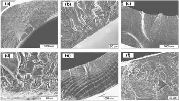
Figure 8 presents the SEM graphs of the crack initiation area on fracture surfaces for different strain ranges at 600 °C. Multiple crack initiation occurs on the fracture surface, which is the distinct feature of low cycle fatigue. At Δε = 0.7%, the crack initiation appears at the inner surface of the specimen [Fig. 8(a)] and then propagates to the external surface [Fig. 8(b)]. There are remarkable evidences of oxidation and steps, which indicate that the crack initiation results from both oxidation and stress effect. At Δε = 1.0% [Fig. 8(c)], the crack initiation is located at the inner surface and the characteristic of oxidation is revealed by partial enlargement [Fig. 8(d)]. At Δε = 1.2% [Fig. 8(e)], the crack initiation appears at the inner surface. The pronounced oxidation and wider fatigue striation occur on the crack source area by partial enlargement, which indicates the rapid crack propagation [Fig. 8(f)].
SEM results of crack source region for different strain ranges at 600°C: (a), (b) △ε=0.7%, (c), (d) △ε=1.0%, (e), (f) △ε=1.2%.

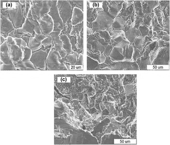
According to the DSA mechanism, the pinning effect can lead to stress concentration which makes the material present unique fracture characteristics. Figure 9 shows the SEM graphs on the crack propagation area of fracture surface for different strain ranges at 600 °C, where the features of intergranular fractures can be observed. The fracture features are attributed to the DSA induced inhomogeneous deformation since grain boundaries are preferred sites for DSA. Reference Rodriguez23 Thus, it is reasonable to consider that grain boundaries, which restrict the dislocation movement, facilitate the formation of solute atom atmospheres. When DSA operates, the pining of DSA can lead to a stress concentration and inhomogeneous deformation at the grain boundaries. Therefore, the features of the intergranular fractures can appear on the crack propagation area.
SEM results of crack propagation region for different strain ranges at 600°C: (a) △ε=0.7%, (b) △ε=1.0%, (c) △ε=1.2%.

V. CONCLUSIONS
-
(1) Low cycle fatigue tests for different strain ranges were conducted for 316L stainless steel under uniaxial loading at 20 and 600 °C. Results show that DSA occurs for all strain ranges at 600 °C. The difference of serrated yielding characteristics among different strain ranges can be explained by the dependence of vacancy concentration on strain range. The maximum stress drops at half-life are 10.4, 1.5, and 5.4 MPa, respectively. The significant trend for serrated flow occurring at Δε = 0.7% may be attributed to the most effective interaction between solute atoms and dislocations.
-
(2) For smaller strain ranges, the hardening ratio and softening ratio at 600 °C are very equal to those at 20 °C, while for larger strain range, the anomalous hardening ratio and secondary hardening behavior are exhibited at 600 °C. The abnormal fatigue behavior can be explained by the different extent of DSA effect during cyclic deformation, the increase in dislocation density during primary cyclic loading, and the collective behavior of dislocations.
-
(3) Obvious DSA occurs in the first few cycles, and then weakens or even disappears. However, the serrated yielding occurs again before fatigue failure. The difference of serrated yielding can be explained by the types of atom atmospheres at different cycles. The serrated wave A is observed for smaller strain ranges, but for larger strain range serrated waves A, B, A + B, C, and B + C appear for different cycles and different stages within one cycle.
-
(4) SEM graphs reveal multiple crack initiation sites at 600 °C and the crack initiation area presents the feature of oxidation and steps. The inhomogeneous deformation induced by DSA results in the intergranular fracture on the crack propagation area.
ACKNOWLEDGMENT
The authors are grateful to the supports of the projects of National Natural Science of Foundation of China (11102119) and Key Project of Chinese National Programs for Fundamental Research and Development (973 Program, 2011CB706504).