


I. INTRODUCTION
Due to their unique electrical, thermal, and mechanical properties, carbon nanotubes (CNTs) have been proposed for a wide range of nanoelectronics applications, including interconnects [Reference Hagmann1, Reference Marulanda2], packages [Reference Morris3], transistors [Reference Postma, Teepen, Yao, Grifoni and Dekker4], passive devices [Reference Xu, Li, Srivastava and Banerjee5], and antennas [Reference Hanson6, Reference Maksimenko, Slepyan, Nemilentsau and Shuba7]. Recently, CNTs have been also proposed as innovative scattering material [Reference Lee, Kang and Kim8], in the realization of absorbing materials in the aircraft industry, in view of replacing conventional materials, like polymeric sheets filled with magnetic or dielectric loss materials, such as ferrite, permalloy. Furthermore, CNTs are also used as filling materials in composite materials, to improve the thermal properties of the interfaces [Reference Maffucci9].
The electromagnetic performance of CNT absorbing materials and CNT-filled composite materials are strongly related to their scattering response: the analysis of the scattering from CNT structures has therefore assumed a relevant role in the literature [Reference Nasis, Plegas, Sofronis and Anastassiu10–Reference Slepyan, Krapivin, Maksimenko, Lakhtakia and Yevtushenko12]. The starting point is a reliable model for the electrodynamics of CNT able to take properly into account the graphene crystalline [Reference Slepyan, Maksimenko, Lakhtakia, Yevtushenko and Gusakov13].
The π-electrons of the carbon atoms are delocalized and contribute to the CNT electric current. An accurate electromagnetic model should describe both the interaction of the π-electrons with the ions lattice and their collective effects [Reference Ferry and Goodnick14]. A possible approach is given by numerical simulations based on first principles, according to quantum mechanics [Reference Miyamoto, Louie and Cohen15]. Unfortunately, this approach is unable to simulate structures like CNT arrays, since it is likely to become computationally expensive, and hence simpler models are needed. If interband transitions are absent, the π-electrons may be regarded as “quasi-classical particles” and a semi-classical model may be used to describe their dynamics. A first example is the description of the CNT electrodynamics within the frame of Luttinger liquid theory, given in [Reference Burke16]. Another approach consists in deriving the transport equation for the π-electrons from the semi-classical theory of the electrical conduction [Reference Ashcroft and Mermin17–Reference Salahuddin, Lundstrom and Datta19]. The authors have recently generalized this approach [Reference Miano, Forestiere, Maffucci, Maksimenko and Slepyan20], including in the model the effects related to the CNT size, chirality, and temperature. Furthermore, they have shown [Reference Forestiere, Maffucci and Miano21] that the model given in [Reference Miano, Forestiere, Maffucci, Maksimenko and Slepyan20] is consistent with the fluid description of the CNT electrodynamics proposed in [Reference Miano and Villone22]. The model involves the concept of an equivalent number of conducting channels, i.e. the number of the subbands in the neighbors of the CNT Fermi-level that significantly contribute to the electric conduction. In this paper, we use such a model, which is briefly summarized in Section II.
The analysis of electromagnetic scattering from one or more finite-length CNTs may be faced by recasting the problem either into a Hallen or a Pocklington equation [Reference Nasis, Plegas, Sofronis and Anastassiu10–Reference Slepyan, Krapivin, Maksimenko, Lakhtakia and Yevtushenko12]. The well-known problem to be handled to obtain the numerical solution of such equations is the singularity of the kernels. Usually an approximated kernel is used, relying on the so-called thin-wire approximation, which, however, may lead to numerical problems (oscillations in the numerical solution at the end points of the antenna) as pointed out in [Reference Fikioris23]. A possible solution to this problem is given in [Reference Slepyan, Krapivin, Maksimenko, Lakhtakia and Yevtushenko12], where a formulation in terms of the Hertzian potential and the Wiener–Hopf technique are used to analyze the case of semi-infinite CNTs. In this paper, we analyze the scattering problem by using the Pocklington formulation with the complete kernel, by means of an analytical extraction procedure of the contribution of the kernel singularity. Section III is devoted to the formulation of the scattering problem, either from an isolated CNT or from a CNT array. Section IV shows the considered case studies. A comparison with the existing literature is provided, along with the analysis of the array effect on the scattering.
II. ELECTRODYNAMICS OF A CNT SHELL
Provided that there are no intershell tunneling currents between adjacent CNT shells, the electromagnetic response of a complex structure of CNTs may be always reduced to the study of a set of single CNT shells interacting between them only through the macroscopic electromagnetic field.
A) Band structure of a CNT shell
A CNT is made by rolling up one or more sheets of a mono-atomic layer of graphite (graphene). A single-walled carbon nanotube (SWCNT) is made up by a single shell, usually with radius of the order of few nanometers; instead, a multi-walled carbon nanotube (MWCNT) is made by several nested shells, with radius ranging from tens to hundreds of nm. The graphene sheet is reported in Fig. 1(a), along with the chiral vector c describing how it is rolled: c = n a1 + m a2, where n and m are integers and a1 and a2 are the basis vectors of the graphene lattice, of length  , being b 0 = 0.142 nm the interatomic distance. The CNT radius is given by
 . CNTs with n = 0 (or m = 0) are called zigzag, those with n = m are the armchair CNTs and those with 0 < n ≠ m are the chiral CNTs. Although the graphene layer is a zero-gap semiconductor, when it is rolled up it may become either metallic or semiconducting, depending on its geometry (e.g. [Reference Saito, Dresselhaus and Dresselhaus24]). The general condition to obtain a metallic CNT is |n − m| = 3q, where q = 0, 1, 2.
(a) The unrolled lattice of a CNT: lattice basis vectors of graphene, unit cell of grapheme, and the chiral vector of the tube graphene lattice. (b) The reciprocal graphene lattice and the first Brillouin zone referred to a CNT shell.

In order to analyze the band structure of a CNT shell, it is useful to start from the graphene reciprocal lattice (Fig. 1(b)), described in the Cartesian coordinate system (k x, k y) having the origin at the center of a hexagon, being the k y axis oriented along the hexagon side. The basis vectors are  and
 . The first Brillouin zone of a CNT shell is the set
 of N parallel segments depicted in Fig. 1(b): the distance between two adjacent segments is Δk ⊥ = 1/r c. By assuming the CNT axial length to be large compared to the unit cell dimension, the axial wave vector is almost continuous. On the contrary, due to the periodic boundary condition along the CNT circumference, the transverse wave vector k ⊥ is quantized: μΔk ⊥ with μ = 0, 1, … , N − 1.
The dispersion relation for the SWCNT consists of 2N one-dimensional energy subbands E μ(±), whose expression involves the dispersion relation of the graphene layer, given by
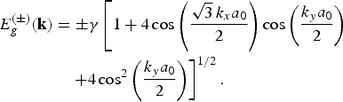
Here the signs + or − indicate the conduction and the valence energy band, respectively, and γ = 2.7 eV is the carbon–carbon interaction energy. The valence and conduction bands of the graphene touch themselves at the graphene Fermi points. Let us denote with kF the wave number at such points. In a neighborhood  of each Fermi point, expression (2) may be approximated as
 , where v F is the Fermi velocity of the graphene given by
 (
 ) and
 is the Planck constant. Only the energy subbands that pass through or are close to the Fermi level contribute significantly to the nanotube axial electric current.
B) Electron transport of π-electrons
In the low-frequency range (up to terahertz), the interband transitions are absent and a semi-classical description can be used to model the π-electron dynamics. To describe the π-electron dynamics in the μth CNT subband, we introduce the distribution function f μ(±) (z, k, t), satisfying the quasi-classical Boltzmann equation [Reference Miano, Forestiere, Maffucci, Maksimenko and Slepyan20]:

where e is the electron charge, E z = E z(z, t) is the longitudinal component of the electric field at the CNT surface,  is the longitudinal velocity of the conduction/valence electrons and ν is the relaxation frequency. The distribution at equilibrium is given by

where F[E] the Dirac–Fermi distribution function with electrochemical potential equal to zero,  , with k B being the Boltzmann constant and T the nanotube absolute temperature. Assuming time-harmonic steady state for the electric field and the surface current density, i.e.
 , the constitutive equation for the CNT is represented as:

where  is the CNT longitudinal conductivity in the wave number and frequency domain. In the small perturbation limit around the equilibrium from equation (2), we obtain [Reference Miano, Forestiere, Maffucci, Maksimenko and Slepyan20]

The corresponding constitutive equation in the spatial and frequency domain is given by [Reference Miano, Forestiere, Maffucci, Maksimenko and Slepyan20]

where ρs(z, ω) is the surface charge density, and σc = Mv F/πr cνR 0 is the long wavelength static limit for the axial conductivity. In its expression, we have introduced the quantum resistance  and the equivalent number of conducting channels defined as

This parameter represents the average number of subbands around the Fermi level. It depends on the number of segments s μ passing through the two circles of radius k eff and centered at the two Fermi points of graphene. The radius k eff is a function of the absolute temperature T: for k eff ≪ 1/a 0 it is  , and therefore M increases as temperature increases. Indeed the chirality of a CNT plays a relevant role in determining M, as depicted in Fig. 2 in which the typical behavior for metallic (a) and semi-conducting (b) CNTs is shown.
Equivalent number of conducting channels versus CNT shell diameter, computed at T = 273 and 373 K.

Relation (6), which can be regarded as a non-local Ohm's law, may be rewritten as follows, by applying the charge conservation law:

Here the per-unit-length parameters (kinetic inductance L K, quantum capacitance C Q, and resistance R) are given by:

which generalize those used in literature (e.g. [Reference Salahuddin, Lundstrom and Datta19]), usually referred to the case of metallic shells of small radius for which it is M ≈ 2.
Equation (8) may be regarded as a balance of the momentum of the conduction electrons and represents their transport equation: the term on the left-hand side represents the electron inertia. The first term on the right-hand side represents the quantum pressure arising from the zero-point energy of the electrons, the second term describes the action of the collective electric field, whereas the third one is a relaxation term due to the collisions.
Note that the relaxation frequency may be expressed as ν = v F/l mfp, where l mfp is the mean free path of the electrons. In conventional conductors, l mfp is of the orders of some nm, and therefore it is ν → ∞, and hence (6) becomes a local relation. The mean free path of CNTs, instead, may extend up to the order of µm, and therefore the range of non-locality is relatively large.
III. SCATTERING FROM CNT
A) Scattering from an isolated CNT and from an array of CNTs
Let us consider an isolated SWCNT of length 2L and radius r c, with 2L ≫ r c, aligned to the z-axis of a Cartesian coordinate system, Fig. 3(a). A plane wave  is impinging on the CNT, inducing a current and a charge distribution all over its surface. Due to the linearity of the equation involved in the problem, the total electric field can be seen as the superposition of the incident field and the scattered one, i.e.

(a) The single-CNT scattering problem; and (b) a linear array of CNTs.

As the current and charge distribution are almost uniform along the CNT contour at fixed z (e.g. [Reference Miano and Villone22]), the current intensity I(z) and the p.u.l. electric charge Q(z) are simply given by I(z) = 2πr cJ z(z) and Q(z) = 2πr cρs(z), and hence (6) may be rewritten as

where R is the p.u.l. resistance defined in (9) and E z(z) is the z component of the total electric field evaluated on the surface of the CNT. The above equation has to be coupled with the charge conservation law:

Let us introduce the magnetic vector potential A = Az(z) and the scalar electric potential V generated by the induced current and charges evaluated at the CNT surface. The potentials are expressed as

where  T is the linear integral operator

defined through the following kernel:

K is the complete elliptic integral of the first kind,  and m = 2r c/ρ. As the CNT radius is electrically small for the typical frequencies of interest (up to THz), the term g ω(ζ) in (15) is satisfactorily approximated by

Applying (13), the total longitudinal electric field E z(z) is given by

being E 0z(i)(z) the longitudinal component of the incident field.
Applying the above results, the current distribution I(z) along the CNT is the solution of the following system of integro-differential equations:

where the kinetic inductance L k and the quantistic capacitance C Q have been introduced in (9). The solution of (18) may be performed numerically. If no approximation is given to the kernel (e.g. thin-wire approximation as in [Reference Hanson6–Reference Nasis, Plegas, Sofronis and Anastassiu10]) the numerical model must properly take into account for the logarithmic singularity appearing in the static part of the kernel g(ζ) when  :

Once the CNT current distribution I(z) is known, the related far-field scattered field can be directly evaluated as:

being ς the free-space intrinsic impedance.
B) Scattering from an array of CNTs
The above model can be also used effectively for analyzing the scattering from an array of SWCNTs providing that the tunneling currents between adjacent CNTs may be disregarded. Following the stream of what has been done above, let us consider a 1D array of identical SWCNTs arranged along the x-axis of a Cartesian coordinate system and parallel to the z-axis, as depicted in Fig. 3(b). Each of them has a length 2L and radius r c. The system is always illuminated by a plane wave  . The current and p.u.l. charge are almost uniform along the contour of each CNT at fixed z, i.e. for any CNT I i(z) = 2πr cJ z,i(z) and Q i(z) = 2πr cρs,i(z). Therefore, the ith CNT constitutive equation is the same of the single CNT one, (11). The potentials may be expressed as

where  and T is the linear integral operator

defined through the kernel:

being  .
As done for the case of an isolated CNT, the problem is solved without any kernel approximation, by using a Galerkin finite-element scheme, and an analytical integration of the kernel singularity.
IV. CASE STUDY
A) Transmitting property of an isolated CNT shell
In the first case study, the transmitting antenna in [Reference Hanson6] is considered. The CNT length is L = 10 µm, the radius r c = 2.72 nm, the parameter 1/ν = 3 ps, and the temperature is T = 300 K. The excitation input used in our simulations is the frill generator [Reference Fikioris25] defined by

where

Figure 4 shows the current distribution on the CNT antenna at various frequencies. The results obtained here are in good agreement to those obtained in [Reference Hanson6], with little differences due to the thin-wire approximation used in [Reference Hanson6] to evaluate the kernel.
Current distribution on the CNT antenna at (a) 10 GHz, (b) 160 GHz, (c) 292 GHz, and (d) 578 Ghz.

B) Scattering from an isolated CNT shell
Let us first introduce a benchmark case to test the validity of our model. In the following, we refer to the case study of an isolated SWCNT of length 20 µm analyzed in [Reference Hao and Hanson11]. In order to compare the results, we assume the same operating conditions as in [Reference Hao and Hanson11], where the incident field is a TEM wave with wavevector perpendicular to the CNT axis and the field is evaluated at a distance of 100 µm.
Figure 5 shows the scattered electric field for the two CNT lengths, computed for variable frequencies up to 1 THz, in the angular direction of the maximum scattering. The plots highlight the strong dependence of the scattering characteristics from the CNT length, as already pointed out in the literature [Reference Hao and Hanson11]. The results obtained here are in good agreement with those obtained in [Reference Hao and Hanson11]. Figure 6 reports the current distributions computed at the frequencies indicated in Fig. 5 with circles, corresponding to the first two maxima and the first minimum.
Scattered electric field for a 20 µm-long CNT, with radius of 2.72 nm at 300 K, illuminated by a TEM plane wave impinging orthogonally. The scattered field has been evaluated at a distance of 100 µm.

Spatial distributions of the current along the CNT at the frequencies indicated in Fig. 5.

C) Scattering from an array of CNTs
Let us consider the case of an array of nine identical CNTs, of radius r c = 2.72 nm, length 2L = 8 µm, 1/ν = 3 ps at the temperature is T = 300 K. The nanotubes are equispaced and the inter-axis distances analyzed are Δ x = L/4 = 1 µm, Δ x = L/2 = 2 µm, and Δ x = L = 1 µm. For these distances, the tunneling currents between adjacent CNTs are negligible. The incident field, as in the isolated CNT simulations, is assumed to be a TEM wave with wave vector perpendicular to the CNT axis and the field is evaluated at a distance of 100 µm. When the inter-axis distance is comparable to the CNT half-length the current distribution along the nanotubes resembles one of the isolated CNTs and the scattered field can be evaluated considering the nine CNTs as if they do not interact electromagnetically.
These results are reported in Fig. 7. In Fig. 7(a), the current distribution on the central CNT of the array, when the structure is illuminated by a TEM plane wave of wavelength 300 µm, is reported in the case of isolated CNT and for three considered inter-axis distance. In Fig. 7(b), the maximum value of the scattered electrical field is reported in the same conditions.
(a) Current distribution on the central CNT of the array when the structure is illuminated by a TEM plane wave of wavelength 300 µm. (b) Electric field magnitude scattered by the array. The scattered field has been evaluated at a distance of 100 µm.

V. CONCLUSIONS
Electromagnetic scattering properties of finite-length SWCNTs, either isolated or in arrays, have been investigated up to terahertz frequencies. The scattering problem has been formulated in terms of a Pocklington-like integral equation. The electromagnetic behavior of each CNT shell is described through a semi-classical fluid model. The integral equation is solved using a Galerkin finite-element scheme without any kernel approximation, because the kernel singularity is analytically integrated. An array of CNTs is simulated, showing that the mutual coupling is negligible if the inter-axis distance is comparable to the semi-length of the CNT. The coupling is mainly due to the electrostatic interaction between the CNT: this result can be useful to decrease the computational burden of simulating large arrays. Since the proposed approach allows dealing with a CNT shell of arbitrary chirality, it can be used for analyzing the electromagnetic scattering from more complex structures composed of single-walled CNTs with different chirality such as multi-walled CNTs and bundles of CNTs, providing that the direct coupling of electronic states of adjacent CNT shells may be disregarded (intershell tunnelling currents are negligible) and only the electromagnetic coupling is important.
ACKNOWLEDGEMENT
This work was supported in part by the EU FP7 CACOMEL project FP7–247007
 Andrea G. Chiariello received the Laurea degree in electronic engineering (summa cum laude), in 2004 and Ph.D. degree in electrical engineering, in 2007 from the University of Naples “Federico II”, Naples, Italy. In 2006, he was a visiting scholar at the Department of Electrical and Computer Engineering, the University of Illinois, Urbana-Champaign. In 2008, he teaches on circuit theory at the University of Molise. Since august 2008 he has a post doc fellowship in the department of electrical engineering of the University of Naples “Federico II”. His research interests are the electromagnetic modeling of high-speed interconnects, the electromagnetic compatibility, and electromagnetic modeling of nanointerconnect.
 Carlo Forestiere received the B.Sc. (summa cum laude) and the M.Sc. degrees (summa cum laude) in electronic engineering, in 2005 and 2007 respectively, from the University of Naples “Federico II”, Naples, Italy, where he is currently working toward the Ph.D. degree in electrical engineering. In 2009, he was a visiting scholar at the Photonic Center, Boston University, Boston, USA, where he was involved in the electromagnetic modeling of plasmonic nanostructures. His research interests and activities include carbon nanotubes electrodynamics, plasmonic nanostructures, electromagnetic scattering, and computational electromagnetics.
 Antonio Maffucci received in 1996 the Laurea degree in electronic engineering summa cum laude and in 2000 the Ph.D. degree in electrical engineering from the University of Naples Federico II, Italy. In 1997, he was with the nuclear fusion laboratory JET (Culham, UK). From 1998 to 2002 he was with the Department of Electrical Engineering, University of Naples Federico II. He is currently an Associate Professor at the Department DAEIMI of the University of Cassino, Italy, where he was Researcher from 2002 to 2005. He teaches courses on basic electrical engineering, circuit theory, and electromagnetic compatibility at the Faculty of Engineering, University of Cassino. His research interests include electromagnetic and circuital modeling of microelectronics and nanoelectronics interconnects, carbon nanotube modeling, computational electromagnetism, and electromagnetic compatibility. He is the author of about 100 technical papers on international journals, conference proceedings, and scientific books. He is also coauthor of the book Transmission Lines and Lumped Circuits (Academic Press, New York, 2001). He is an Associate Editor of the IEEE Transactions on Advanced Packaging, and is a member of the IEEE Nanotechnology Council Nanopackaging Technical Committee.
 Giovanni Miano received the Laurea (summa cum laude) and Ph.D. degrees in electrical engineering from the University of Naples Federico II in 1983 and 1989, respectively. From 1984 to 1985, he was with the PS Division, CERN, Geneva, Switzerland, where he was engaged in research on magnetic plasma lenses. From 1989 he is a Full Professor at the Faculty of Engineering of the University of Naples Federico II, where he served as a Researcher until 1992 and as an Associate Professor from 1992 to 2000. Since 2005, he has been the Director of the Dipartimento di Ingegneria Elettrica. In 1996, he was a Visiting Scientist at the GSI Laboratories, Darmstadt, Germany, and in 1999 a Visiting Professor at the Department of Electrical Engineering, University of Maryland, College Park. His research interests include ferromagnetic materials, nonlinear dielectrics, plasmas, electrodynamics of continuum media, nanotechnology, and modeling of lumped and distributed circuits. He is the author and coauthor of more than 70 papers published in international journals, 60 papers published in international conference proceedings, two items in the Wiley Encyclopedia of Electrical and Electronic Engineering (Wiley, New York, 1999), and the monograph Transmission Lines and Lumped Circuits (Academic, New York, 2001). He is a Reviewer for various journals of the IEEE and past member of the Editorial Boards of the Conference on Electromagnetic Field Computation and the Conference on the Computation of Electromagnetic Field.



