I. INTRODUCTION
Relevant implications that temperature sensor has in everyday life, including important applications in fields such as biomedicine, food industry, and aerospace industry, have prompted an intensive research concerning new sensing materials. Reference Martínez, Otero, Bosch-Navarro, Coronado, Martí-Gastaldo and Prima-Garcia1,Reference Yogeswaran and Chen2 The main requirements of a good temperature sensor are high sensitivity, fast response, low cost, and high reliability. Up to now, temperature sensors are mostly based on metal Reference Sun, Zhu, Wang, Zhong, Wei, Wu and Zhu3,Reference Schafft and Suehle4 and metal oxide semiconductors. Reference Kim5 Moreover, the birth of artificial skins Reference Someya, Kato, Sekitani, Iba, Noguchi, Murase and Sakurai6–Reference Hou, Wang, Zhang, Zhao, Zha and Dang8 and wearable electronic devices Reference Mattmann, Clemens and Tröster9,Reference Cohen, Mitra, Peterson and Maharbiz10 has boosted many efforts toward the miniaturization of sensors as they would lead to soft and flexible materials. In this direction, graphene has received significant attention because of its potential as highly flexible electrically conductive electronics for various applications. Reference Kong, Le, Li, Zunino and Lee11 While two-dimensional (2-D) graphene nanoplatelets (GNPs) have inherited the excellent sensing function of graphene, the low cost and ease of production make it more commonly used. GNPs have drawn a lot of interest and possess many advantages compared with graphite due to their high mechanical properties (about 1 TPa for either single-layer or multilayer graphene Reference Lee, Wei, Kysar and Hone12 ), excellent electrical conductivity (about 1.0 × 10⁻⁶ Ω·cm resistivity for pure graphene but more than two orders of magnitude higher for graphite Reference Chen, Jang, Xiao, Ishigami and Fuhrer13 ), thermal conductivity (about 5000 W/mK, Reference Watanabe, Yamaguchi, Nakamura and Natori14–Reference Balandin, Ghosh, Bao, Calizo, Teweldebrhan, Miao and Lau17 much higher than that for graphite with thermal conductivity of 5–20 W/mK), and extremely large surface area. Reference Geim18,Reference Choi, Lahiri, Seelaboyina and Kang19 The platelet shape of graphite also benefits the composite by providing increased tortuosity for molecular transport which enhances barrier properties to small molecules. Reference Wu and Drzal20
At present, GNPs have been mainly applied in biochemical sensors, such as for drug testing Reference Yan, Tang, Deng and Li21 and gas monitoring. Reference Wu and Drzal20 But there were few reports on its temperature sensitivity. Multiwall carbon nanotubes (MWCNTs) are commonly used as temperature sensing material in flexible materials, Reference Mohiuddin and Hoa22,Reference Neitzert, Vertuccio and Sorrentino23 and polymer matrix is widely used in most flexible temperature sensors because it can provide stability and power support, and the differences in thermal expansion rates of filler and matrix would bring higher sensitivity. But the matrix would also make the sensor dull in response time. However response time is one of the most important characteristics of temperature sensor. Thus, actually, GNPs are also, even more suitable as a temperature sensing material because of its large surface area, directly contacting with the temperature field without using a polymer matrix and the high heat conductivity.
In this article, GNPs were used to fabricate a film on interdigitated electrodes. The temperature depended resistance change was acquired and explained in detail. High sensitivity of GNPs was observed comparing with MWCNTs and other materials reported in references. Repeatability and hysteresis were illustrated and fast response to step temperature was obtained comparing with MWCNTs film and common temperature sensors.
II. EXPERIMENTAL
A. Materials
The GNPs were supplied by Chengdu Organic Chemicals Co., Ltd. (Sichuan Province, China) with a purity >99.5 wt%. The GNPs had a thickness of 4–20 nm, a diameter of 5–10 μm, and layers <30. The MWCNTs were purchased from Chengdu Organic Chemicals Co. Ltd. (Sichuan Province, China), Chinese Academy of Sciences, with a diameter of 20–30 nm, a length distribution <10 μm, and a purity >95%.
In this experiment, field emission scanning electron microscopy was carried out to characterize the morphology of the sample. Temperature and humidity programmable chamber is supplied by DongGuan Bell Experiment Equipment Co, Ltd. (Guangdong Province, China).
B. Preparation of samples
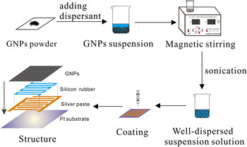
The fabrication process has been shown in Fig. 1. To fabricate the sensor, first naphtha was added into GNPs powder, thereafter mechanically stirring for 30 min and sonicating for 2 h to obtain a well-dispersed suspension solution. Then the suspension solution was dropped onto an interdigital electrode on polyimide substrate. The interdigital electrode was coated using silver paste as conductive part and silicon rubber as insulation part to connect GNPs as glue. The GNPs film was cured at room temperature. The film fabricated is 0.5 cm (length) × 0.5 cm (width). The thickness of the film is associated with the concentration of the suspension solution by a certain dosage (0.1 mL). The suspension solutions with different concentrations (0.05, 0.1, and 0.2 mg/mL) were made and three GNPs films with different thickness were fabricated. The thickness h of the films was calculated according to the equal
 $h = V \cdot c/({\rm{\rho }} \cdot S)$
where V is the volume of the dropped suspensions, c is the concentration, ρ is the density of GNPs (ρ = 1.06g/cm3), and S is the area of the sensor. The thickness h respectively got to be 188 nm, 370 nm, and 755 nm. Film with concentration of 0.05 mg/mL (h ≈ 188 nm) was affected greatly by mechanical bending and could not keep the continuity of the film when subjected to bending or tension, and film of 0.2 mg/mL (h ≈ 755 nm) was sluggish in response due to its higher thickness (not shown in this article). Film with concentration of 0.1 mg/mL (h ≈ 370 nm) was selected for further study in consideration of both the mechanical property and sensitivity. A MWCNTs film was fabricated by the same method for the sake of comparison, and suspension with MWCNT concentration of 0.17 mg/mL was made to ensure the MWCNT film thickness to be about 370 nm.
The fabrication process of GNPs film.

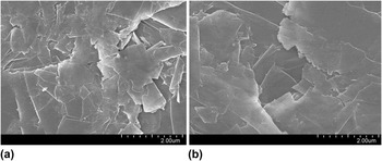
A preheat treatment has been carried out on both the samples to enhance the stability and sensitivity. The sensors were heated rapidly to 150 °C and then cooled in the air to the room temperature. The low preheating temperature is decided by the silicon rubber, the insulation part of electrode, which would degrade at about 200 °C. Figure 2(a) shows the initial morphology of the GNPs. The obvious sheet structure was exhibited and there were many folds on the surface. The initial overlap cases of the graphene layers are inconsistent and easy to be changed, which would impact the stability of sensor. Electron transport would be obstructed, Reference Sun, Zhu, Wang, Zhong, Wei, Wu and Zhu3 which increases the resistance. The preheat treatment was taken to provide an improved match between each layer, and the surface morphology was much flatter after preheating [Fig. 2(b)], leading to an improvement of conductivity and more stable and uniform overlap case. In the experiment of temperature effect, ripples would appear on the graphene layers as temperature rises because of thermal disturbance, and distance between layers increases as thermal expansion, causing the increase of resistance. And this increase of resistance would be more obvious than that of initial sensor with more ripples and further distance originally without preheating. In other cases, the metal–carbon materials contact resistance can be often substantially lowered by a local contact preheating with Joule heating. Reference Dong, Youkey, Bush, Jiao, Dubin and Chebiam24,Reference Woo, Duesberg and Roth25
SEM micrograph of the morphology of the GNPs (a) before preheating (b) after preheating.

III. RESULTS AND DISCUSSION
A. Electrical measurements tests
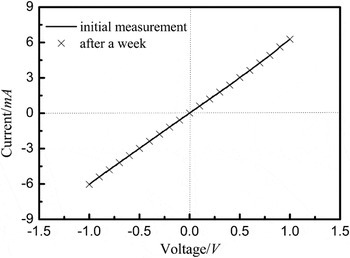
The electrical measurements of GNPs film has been performed in a two-point contact geometry using a Keithley model “4200” source-measurement unit, as shown in Fig. 3. A superlinear I–V characteristic has been observed. Self-heating can, however, be neglected for the investigated sample. For confirming the long-term stability of the sample conductivity and the electrical contacts, the sample was put aside in the room environment for one week. Measurements before and after this period demonstrate the excellent stability of the sensing element.
(I?V) characteristics of an GNPs film measured directly after sample preparation and after putting aside in the room environment for one week.

B. Stability at constant temperatures
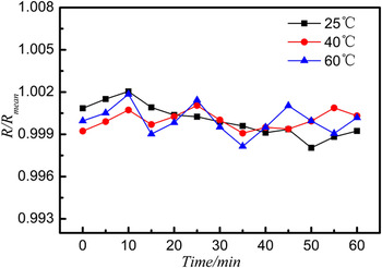
The resistance stability of GNPs film has been examined at constant temperatures of 25 °C, 40 °C, and 60 °C during an hour, as shown in Fig. 4. The sample was tested three times and the mean value was calculated. The fluctuation ranges were all less than 1 Ω. The great stability laid the foundation for highly accurate measurement to weak temperature change. Reference Sun, Zhu, Wang, Zhong, Wei, Wu and Zhu3 Because GNPs has 2-D plane structures and large surface area, the large surface van der Waals force of GNPs particle–particle will result in GNPs reunion. Reference Cai, Huang, Wang, Liu and Zhang26 For geometrical considerations, graphene layers are easier to structure in a triangle framework, which established a stable conducting network.
The resistance stability of GNPs film at constant temperatures.

C. Sensitivity to temperature
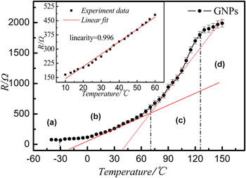
Figure 5 shows the change of resistance R as temperature rising. The sample was test three times and the mean value was calculated. The maximum standard error worked out to be 60.3 at 150 °C. R of the GNPs first decreases silently below −30 °C and then increases nonlinearly with respect to temperature. The temperature effect of GNPs film can be explained by two factors: (i) a new conductive network of GNPs was established by thermal expansion. The GNPs neat rows at room temperature with good conductivity. While the temperature rises the air in the gap between graphene layers inflated, and some ripples appear on the graphene layers as thermal disturbance, Reference Dewapriya, Phani and Rajapakse27 which leads to the decrease of the contact area of graphene layers. And the distance between graphene layers would increase the thermal expansion and the tunnel area decreases at the appearance of the ripples. With the distance of two neighboring graphene layers increasing to above 1 nm (i.e., cutoff distance), tunneling effect would be weaker, compared with the original conducting path and tunneling current, which cause the increase of R. (ii) It is known that the temperature dependence of the electrical conductivity of system is affected by the e–ph coupling. Reference Mousavi and Bagheri28 In semiconductors due to the e–ph coupling, the quasiparticle weight increases with rising temperature which causes an increase in the electrical conductivity when temperature is low. While the trend of e–ph coupling will be close to metallic properties when the temperature is above a specified value. The phonon and the electron coupling rate in the GNPs film increases, which decreases the quasiparticle weight of the electron excitation and affects the electron movement in the GNPs.
Temperature dependent resistance of GNPs film in the temperature region of -40∼150°C. Inset images in figures show the great linearity of the resistance from 10 to 60°C.

The temperature-dependent resistance of GNPs film is divided into four areas (shown in Fig. 5). In zone A, the temperature is below −30 °C, negative temperature coefficient effect is observed. The increase of resistance brought by thermal expansion is weaker than the decrease caused by e–ph coupling model at low temperature, leading to the decrease of resistance. Positive temperature coefficient (PTC) effect begins to appear when temperature is above −30 °C (zone B). Tunneling effect brought by thermal expansion becomes stronger, which lead to a steady increase of resistance. As the temperature go on increase (zone C), PTC effect becomes intense because of the joint action of e–ph coupling model at high temperature and thermal expansion. The effect brought by thermal expansion becomes sharp as the distance between the graphene layers increases furthermore and even beyond the application scope of tunneling effect somewhere. When the temperature was above 130 °C (zone D), the effect brought by thermal expansion decreased, which causes weakness of PTC.
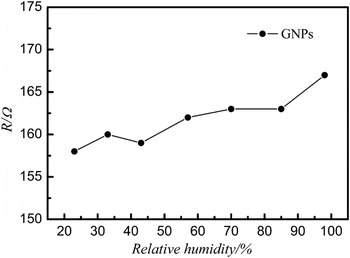
Heating the film would reduce the moisture content, thereby, changing its resistivity. Reference Mitra, Singha and Chakravorty29 So the humidity of the film may have some influence on its temperature effect. To remove the interference and test the validity or otherwise of this situation, simple measurement of electrical resistance as a function of relative humidity was carried out. The change of resistance with different humidity levels was tested (as shown in Fig. 6). The sensor was tested for three times and the maximum standard error worked out to be 0.61. The change of resistance (the maximum value about 10 Ω) was slight and could be neglected in comparison with the change brought by temperature.
The influence of humidity on resistance.

Temperature region of 10–60 °C was selected as the sensor range, which temperature interval was representative and had high frequency of occurrence in our activities of daily life, for further research. In this temperature region, the resistance of GNPs increased almost linearly (the linearity about 0.996), as show in iconography of Fig. 5.
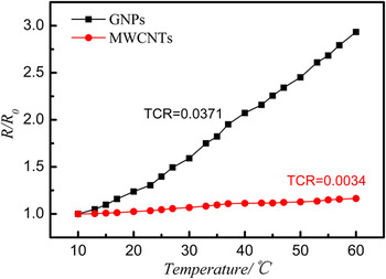
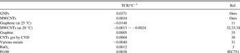
The change of relative resistances of GNPs film and MWCNTs film versus rising temperature (from 10 to 60 °C) is shown in Fig. 7. The black line stands for GNPs film, and the red line is MWCNTs film. The electrical resistance change ratio is related to the temperature coefficient of resistance (TCR, defined as the relative change of resistance when the temperature is changed by 1 K, i.e., where R 0 refers to the initial resistance). Here the TCR of GNPs film α = 0.0371 °C−1, which is much higher than that of MWCNTs film (about 0.0034 °C−1) and other sensors made from different kinds of materials Reference Jiang, Wang and Li15,Reference Alamus, Li, Hu, Wu, Yuan, Chang, Liu, Ning, Li, Surina, Atobe and Fukunaga30–Reference Ali and Hafez35 and traditional temperature, like Pt100 and metallic oxide, Reference Sun, Zhu, Wang, Zhong, Wei, Wu and Zhu3 as shown in Table I. The main resistance change in this region is caused by thermal expansion. And the relative change brought by the tunneling effect transfer from contact conduction of 2-D planar structure is more obvious and steadier than that caused by the stick structure. And the rebuilding of the conductive network in MWCNTs by thermal expansion is more prominent than GNPs, which offset the breakdown of the conductive network. The different TCR of MWCNTs film with that in reference may be caused by fabrication process.
The relative resistance of GNPs film (black line) and MWCNTs film (red line) as a function of temperature.

TCR value of GNPs film compared with MWCNTs and the previous reported materials.

D. Repeatability and hysteresis
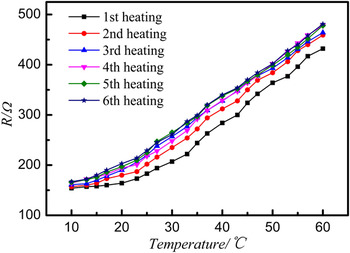
The resistance of GNPs film has also been measured from 10 to 60 °C for six times at a rate of 2°C/min (as shown in Fig. 8). A slight increase (15 Ω) has occurred to the initial resistance after the sixth cooling. And this increased variation concentrated upon the first three heating processes. It progressively decreases and becomes almost zero after the third heating onwards. The change in electrical conductivity with temperature during the heating–cooling cycle is not completely reversible in nature, which may be due to some irreversible changes in conducting networks (the change in conducting network occurs during the heating cycle, but not completely recoverable during the cooling). The conductivity decreases after each cycle of heating and cooling for which same explanation as above is applicable. This decrease of conductivity after repeated cycles of heating and cooling can be attributed to the change of activation energy and the match between each layer which ensure steadier networks. The difference between two neighboring lines diminishes as the heating times added up. It can be seen that the fifth and sixth heating lines got to be basically the same. Formation and breakdown of conducting networks become less prominent and eventually the conductivity becomes stable, leading to the outstanding repeatability.
Change of resistance with temperature for repeated heating process.

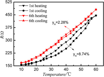
The first and sixth heating and cooling progress are shown in Fig. 9. The resistance of GNPs film was measured under a temperature cycle with a slow rate of heating (2 °C/min) and cooling (4 °C/min). The red line is the resistance change during first heating–cooling cycle, and the black line the sixth cycle. The hysteresis error
 ${y_{\rm{H}}} = {\rm{\Delta }}{H_{\max }}/{Y_{{\rm{fs}}}}^*100\%$
, where
 $\Delta {H_{\max }}$
refers to the maximum difference in the full scale and
 ${Y_{fs}}$
full scale output. The hysteresis is significant, and y
H is about 8.74% during the first temperature cycle. The hysteresis y
H decreases with the heating and cooling times, and 2.28% at sixth cycle, which confirms more excellent signal stability and reproducibility than that (about 5.3%) reported by Khasan Sanginovich Karimov et al.
Reference Karimov, Chani and Khalid31
Hysteresis during 1st (black line) and 6th (red line) heating–cooling cycle.

E. Step response to temperature
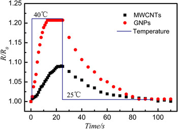
The plunge test method is employed to test the step response and recovery time to temperature in this study. In the plunge test method, the sensor was excited by putting it into an air stream at a temperature of 40 °C from the room environment, and replaced it to the room environment when its resistance reached a stable value. GNPs film and MWCNTs film were tested and the results of the experiment were illustrated in Fig. 10. Normalized resistance of these two sensors is presented. Time constant
 $\tau$
means the time that the response takes to reach 63.2% of stable resistance from the starting initial value. Time constant of GNPs film τG ≈ 5 s, which is significantly smaller than that of MWCNTs
 ${\tau _C}$
(about 12 s), and neck to neck with that of mercury thermometer
 ${\tau _m}$
(about 4 s) and Pt100 (about 5 s),
Reference Qingyang, Yuanliang and Wei36
two of most commonly used temperature sensor. After the step responses being stable, these two sensors were replaced into the room environment. The resistances of the two sensors first decrease rapidly and then slowly. Both of them take about 1 min to reach stable values, and these values are close to their initial resistance.
The response and recover curve of GNPs film (red line) and MWCNTs (black line) to step temperature from 25°C to 40°C.

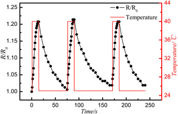
The GNPs film has been measured for three times of temperature response, as shown in Fig. 11, which confirms the excellent signal stability and reproducibility of the present sensor. The response time and recovery time worked out to be the same every time, although small difference occurred on the minimum and maximum resistances. The fast response function of GNPs to temperature shall be attributable to the high thermal conductivity and the larger surface area and makes GNPs suitable for the robot artificial skin to sense the heat source outside.
The response of GNPs to step temperature from 25°C to 40°C for three times.

The response speed could be improved by modifying the size of the sensor, which is just a question of geometry. The hysteresis would be much smaller with a smaller sample, Reference Dong, Youkey, Bush, Jiao, Dubin and Chebiam24 but this is just another scope, as here we concentrated on not just the sensing, but also the self-heating aspect. It is easy to demonstrate by pyranometer measurements on a larger sample. The number of GNPs layers is another influencing factor on electrical response, and single layer or a few layers of graphene is an extreme case. The increase of relative surface area contacting with thermal current directly would also reduce the hysteresis. While it is limited by the cost and manufacture process, no matter the fabrication of material or thin film sensor.
IV. CONCLUSIONS
A temperature sensor was fabricated using GNPs on an interdigital electrode. The effects of temperature (within the range −40 to 150 °C) on the electrical resistance were investigated. The experiment data show that the resistance first decreases with increasing temperature and then reveals PTC effect above −30 °C. Region of 10–60 °C was selected as the temperature sensor range. Great linearity (about 0.996) was observed and high TCR was got (about 0.0371 °C−1) which was much higher than that of MWCNTs and other materials in references. Great repeatability and small hysteresis were obtained and the increase of initial resistance was observed during heating and cooling cycles and this can be due to some irreversible change occurring in the conducting network system. The time constant and the recovery time of the GNPs film are 5.1 s and 1 min respectively. And the time constant is much shorter than that of MWCNTs (12 s) and neck to neck with mercury thermometer (3.6 s) and Pt100 (5 s). The characters of high sensitivity and fast response make GNPs an excellent candidate in temperature-sensing field.
ACKNOWLEDGMENTS
This research was supported by the National Science Foundation of China (No. 61072032) and the Fundamental Research Funds for the Central Universities.