


1. INTRODUCTION
Interest in the generation and dynamics of laser-produced plasma (LPP) has grown significantly in recent decades due to expanding areas of applications and development of new plasma-control methods based on magnetic field confinement. Recently, significant progress has been made in the development of extreme ultraviolet (EUV) sources for lithography (Fazeli et al., Reference Fazeli, Mahdieh and Tallents2011; Kumar et al., Reference Kumar, Singh and Verma2014), inertial and magnetic fusion applications (Sizyuk & Hassanein et al., Reference Sizyuk and Hassanein2014a; Okamura et al., Reference Okamura, Sekine, Ikeda, Kanesue, Kumaki and Fuwa2015), and ultrahigh-precision micro- and nanostructures fabrication for photonic devices (Batani et al., Reference Batani, Vinci and Bleiner2014; Rouleau et al., Reference Rouleau, Puretzky and Geohegan2014; Kim et al., Reference Kim, Roy, Kwon, Song and Park2015). Target ablation by nanosecond lasers during the laser pulse duration will lead to the interaction of laser photons with the expanding vaporized material. This generated plasma has unique characteristics such as high densities and temperatures, mixtures of neutrals, various ion species, and electrons with high velocities, and allows development of laser-beam-guided radiation sources. Requirements for optimizing this plasma depend on the application; specific characteristics can have positive or negative influences on the results. For example, accelerated LPP-generated ions can damage the collecting mirrors in EUV sources or can be used as a powerful source of particles for various accelerators and spectroscopes. These issues stimulate theoretical and experimental investigations to predict the required LPP parameters and control the plasma dynamics, enhancing future device capabilities and optimizing the anticipated results.
An efficient method for LPP analysis and control is the use of external magnetic fields. The interaction of this plasma with a magnetic field in various configurations has been considered in a wide range of studies (Ducruet et al., Reference Ducruet, Kornilov, Fernández de Julián and Givord2006; Kondo et al., Reference Kondo, Kanesue, Tamura, Dabrowski and Okamura2010; Raju et al., Reference Raju, Singh, Gopinath and Kumar2014; Montgomery et al., Reference Montgomery, Albright, Barnak, Chang, Davies, Fiksel, Froula, Kline, MacDonald, Sefkow, Yin and Betti2015; Roy et al., Reference Roy, Harilal, Hassan, Endo, Mocek and Hassanein2015). Spectroscopic analysis was based mainly on the EUV range and visible optical bands. As anticipated, study of the initial stage of plasma expansion and the radiation source dynamics requires high-power fields and X-ray spectrometry measurements. As with conventional X-ray emission spectra, hollow-ion emission spectroscopy has the potential to be a powerful plasma diagnostic tool (Hansen et al., Reference Hansen, Colgan, Faenov, Abdallah, Pikuz, Skobelev, Wagenaars, Booth, Culfa and Dance2014). Regarding LPPs for EUV sources, issues with measurement of desired radiation generation, core plasma variability, and energy conversion efficiency (CE) in the UV range continue to remain critical. Currently many efforts are being spent in developing an efficient and debris free LPP sources at 13.5 nm for next generation EUV lithography (Sizyuk & Hassanein et al., Reference Sizyuk and Hassanein2014b; Elg et al., Reference Elg, Sporre, Curreli, Shchelkanov, Ruzic and Umstadterb2015). Tin is considered as the most efficient material for producing plasmas, which emits strongly in the in-band region (13.5 nm with 2% bandwidth) due to transitions of various ionic stages (Sn8+–Sn14+). The use of external magnetic field is a promising tool for both increasing the EUV CE and mitigation of energetic ionic debris. Our paper studied the details of implementing axial magnetic fields for improving operations of LPP devices. Laser/target interaction is a multicomponent self-consistent process in which a change in one of the integral parts will cause noticeable changes in other parameters. For example, application of an external magnetic field along the hohlraum axis improves the laser/plasma coupling inside the hohlraum and can result in up to 50% increase in plasma temperature as measured by Thomson scattering (Montgomery et al., Reference Montgomery, Albright, Barnak, Chang, Davies, Fiksel, Froula, Kline, MacDonald, Sefkow, Yin and Betti2015). On the other hand, the considered magnetic field strength of 7 T is clearly insufficient for direct changes in the dense core plasma.
Recently, we reported on experimental studies of collimating the LPP using an external axial magnetic field (Roy et al., Reference Roy, Hassan, Harilal, Endo, Mocek and Hassanein2014, Reference Roy, Harilal, Hassan, Endo, Mocek and Hassanein2015). These investigations were done within the scope of EUV source studies for lithography applications to determine methods of optimizing EUV generation and mitigating the negative effects of accelerated particles impinging on the collecting mirrors. However, these studies faced the problem of a clear description of limits for external magnetic field influence on LPP dynamics and, as a result, on EUV source characteristics.
This paper describes in detail our analysis of the effects of an external axial magnetic field on LPP core evolution, generation of EUV radiation, and angular distribution of the output. We also show how the final measured CE depends on the spatial location of the EUV sensor. We analyzed the distance from the laser spot where the applied magnetic field affects LPP, and we estimated the magnitude of a magnetic field that can control LPP core dynamics.
2. MATHEMATICAL AND PHYSICAL MODELS
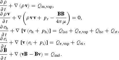
The plasma dynamics in an external axial magnetic field has been investigated using our extended HEIGHTS package (Sizyuk et al., Reference Sizyuk, Hassanein and Sizyuk2006b; Sizyuk & Hassanein, Reference Sizyuk and Hassanein2013b, Reference Sizyuk and Hassanein2015) in application to an axisymmetric LPP case. That package now consist of six main parts: Monte Carlo modeling of laser photon interactions with solid/liquid, vapor, and plasma; heat conduction and vaporization of the target material; magnetohydrodynamics (MHD) of plasma evolution in an axial magnetic field; magnetic diffusion; heat conduction in vapor and plasma; and radiation transport based on weighted Monte Carlo methods. We applied the standard tested scheme with magnetic field (Miloshevsky et al., Reference Miloshevsky, Sizyuk, Partenskii, Hassanein and Jordan2006; Sizyuk et al., Reference Sizyuk, Hassanein, Morozov, Tolkach, Sizyuk and Rice2006a; Sizyuk & Hassanein, Reference Sizyuk and Hassanein2010, Reference Sizyuk and Hassanein2013a, Reference Sizyuk and Hassanein2015) in which the core of the integrated package is the MHD part and the secondary physical processes are taken into account as right-side terms in the general MHD equations set. We considered a two-temperature approximation model:
 $$\eqalign{\matrix{ {\displaystyle{{\partial {\kern 1pt} {\rm \rho}} \over {\partial {\kern 1pt} t}} + \nabla \left( {{\rm \rho} {\kern 1pt} {\bf v}} \right) = {Q_{{\rm m,vap}}},} \hfill \cr {\displaystyle{{\partial {\kern 1pt} {\rm \rho} {\kern 1pt} {\bf v}} \over {\partial {\kern 1pt} t}} + \nabla \left( {{\rm \rho} {\kern 1pt} {\bf v}{\kern 1pt} {\bf v} + {\,p_t} - \displaystyle{{{\bf BB}} \over {4{\rm \pi} {\rm \mu}}}} \right) = 0,} \hfill \cr {\displaystyle{{\partial {\kern 1pt} {e_{\rm h}}} \over {\partial {\kern 1pt} t}} + \nabla \,\left[ {{\bf v}\left( {{e_{\rm h}} + {\,p_{\rm h}}} \right)} \right] = {Q_{{\rm las}}} + {Q_{{\rm e,vap}}} + {Q_{{\rm hc}}} + {Q_{{\rm rt}}},} \hfill \cr {\displaystyle{{\partial {\kern 1pt} {e_{\rm i}}} \over {\partial {\kern 1pt} t}} + \nabla \,\left[ {{\bf v}\left( {{e_{\rm i}} + {\,p_{\rm i}}} \right)} \right] = {Q_{{\rm e,vap}}} + {Q_{{\rm ei}}},} \hfill \cr {\displaystyle{{\partial {\kern 1pt} {\bf B}} \over {\partial {\kern 1pt} t}} + \nabla \left( {{\bf vB} - {\bf Bv}} \right) = {Q_{{\rm md}}}.} \hfill \cr}} $$
Here, ρ is the density; v is the velocity; B is the magnetic field; e h is the hydrodynamic energy, which includes the kinetic and internal parts e h = e kin + e in; e kin = (ρv 2/2) is the kinetic energy; e i is the ionic energy. Pressure has hydrodynamic and magnetic parts: p t = p h + (B2/8 πμ). Magnetic diffusion processes are taken into account as the Q md term on the right side of the magnetic field equation, and μ is magnetic permeability. In these calculations, we assume μ = 1 for the plasma. Thermal conduction in the plasma is included as the Q th term in the energy equation. The target vaporization process is taken into account as Q m,vap and Q e,vap sources in the continuity and energy equations, respectively. The Q rad term describes the radiation transport processes. Energy exchange between electrons and ions Q ei is also taken into account (Braginskii, Reference Braginskii and Leontovich1965). We use Gaussian units unless indicated otherwise. Because plasma parameters are assumed invariable along the azimuthal direction, all derivatives in this direction in Eq. (1) are equal to zero (Fig. 1). Using the r-axis as the radial and z-axis as the axial directions, we transformed Eqs. (1) to a cylindrical coordinates system integrating the obtained expressions for the azimuth angle φ [Eqs. (2)]. Additionally, we neglected the effects of the generated magnetic field in the φ direction for the consideration of laser power densities (Sizyuk et al., Reference Sizyuk, Hassanein, Morozov, Tolkach, Sizyuk and Rice2006a); therefore, magnetic field and velocity have the r- and z-components only. In that way, we obtained the final equation set for modeling of LPPs in the presence of an axial magnetic field:
 $$\matrix{ {\displaystyle{{\partial {\kern 1pt} {\rm \rho}} \over {\partial {\kern 1pt} t}} + \displaystyle{1 \over r}\displaystyle{\partial \over {\partial {\kern 1pt} r}}\left( {r{\rm \rho} {\kern 1pt} {v_{\rm r}}} \right) + \displaystyle{\partial \over {\partial {\kern 1pt} z}}\left( {{\rm \rho} {\kern 1pt} {v_z}} \right) = {Q_{{\rm m,vap}}},} \hfill \cr {\displaystyle{{\partial {\kern 1pt} {\rm \rho} {\kern 1pt} {v_{\rm r}}} \over {\partial {\kern 1pt} t}} + \displaystyle{1 \over r}\displaystyle{\partial \over {\partial {\kern 1pt} r}}r\left( {{\rm \rho} {\kern 1pt} v_{\rm r}^2 - \displaystyle{{B_{\rm r}^2} \over {4{\rm \pi}}}} \right) + \displaystyle{{\partial {\kern 1pt} {\,p_{\rm t}}} \over {\partial {\kern 1pt} r}} + \displaystyle{\partial \over {\partial {\kern 1pt} z}}\left( {{\rm \rho} {\kern 1pt} {v_{\rm r}}{v_z} - \displaystyle{{{B_{\rm r}}{B_z}} \over {4{\rm \pi}}}} \right) = 0,} \hfill \cr {\displaystyle{{\partial {\kern 1pt} {\rm \rho} {\kern 1pt} {v_z}} \over {\partial {\kern 1pt} t}} + \displaystyle{1 \over r}\displaystyle{\partial \over {\partial {\kern 1pt} r}}r\left( {{\rm \rho} {\kern 1pt} {v_z}{v_{\rm r}} - \displaystyle{{{B_z}{B_{\rm r}}} \over {4{\rm \pi}}}} \right) + \displaystyle{\partial \over {\partial {\kern 1pt} z}}\left( {{\rm \rho} {\kern 1pt} v_z^2 + {\,p_{\rm t}} - \displaystyle{{B_z^2} \over {4{\rm \pi}}}} \right) = 0,} \hfill \cr \matrix{\displaystyle{{\partial {\kern 1pt} {e_{\rm h}}} \over {\partial {\kern 1pt} t}} + \displaystyle{1 \over r}\displaystyle{\partial \over {\partial {\kern 1pt} r}}r\left\{ {{v_{\rm r}}\left( {{e_{\rm h}} + {\,p_{\rm h}}} \right)} \right\} + \displaystyle{\partial \over {\partial {\kern 1pt} z}}\left\{ {{v_z}\left( {{e_{\rm h}} + {\,p_{\rm h}}} \right)} \right\} \hfill \cr \qquad ={Q_{{\rm las}}} + {Q_{{\rm e,vap}}} + {Q_{{\rm hc}}} + {Q_{{\rm rt}}}, \hfill} \hfill \cr {\displaystyle{{\partial {\kern 1pt} {e_{\rm i}}} \over {\partial {\kern 1pt} t}} + \displaystyle{1 \over r}\displaystyle{\partial \over {\partial {\kern 1pt} r}}r\left\{ {{v_{\rm r}}\left( {{e_{\rm i}} + {\,p_{\rm i}}} \right)} \right\} + \displaystyle{\partial \over {\partial {\kern 1pt} z}}\left\{ {{v_z}\left( {{e_{\rm i}} + {\,p_{\rm i}}} \right)} \right\} = {Q_{{\rm e,vap}}} + {Q_{{\rm ei}}},} \hfill \cr {\displaystyle{{\partial {\kern 1pt} {B_{\rm r}}} \over {\partial {\kern 1pt} t}} + \displaystyle{\partial \over {\partial {\kern 1pt} z}}\left( {{v_z}{B_{\rm r}} - {B_z}{v_{\rm r}}} \right) = {Q_{{\rm r,md}}},} \hfill \cr {\displaystyle{{\partial {\kern 1pt} {B_z}} \over {\partial {\kern 1pt} t}} + \displaystyle{1 \over r}\displaystyle{\partial \over {\partial {\kern 1pt} r}}r\left( {{v_{\rm r}}{B_z} - {B_{\rm r}}{v_z}} \right) = {Q_{z{\rm, md}}},}\hfill}$$
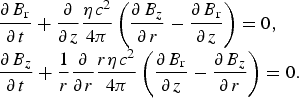
where magnetic diffusion sources Q r,md and Q z,md are calculated using Eqs. (3) for two-vector components following the method described in (Miloshevsky et al., Reference Miloshevsky, Sizyuk, Partenskii, Hassanein and Jordan2006):
 $$\matrix{ {\displaystyle{{\partial {\kern 1pt} {B_{\rm r}}} \over {\partial {\kern 1pt} t}} + \displaystyle{\partial \over {\partial {\kern 1pt} z}}\displaystyle{{{\rm \eta} {\kern 1pt} {c^2}} \over {4{\rm \pi}}} \left( {\displaystyle{{\partial {\kern 1pt} {B_z}} \over {\partial {\kern 1pt} r}} - \displaystyle{{\partial {\kern 1pt} {B_{\rm r}}} \over {\partial {\kern 1pt} z}}} \right) = 0,} \hfill \cr {\displaystyle{{\partial {\kern 1pt} {B_z}} \over {\partial {\kern 1pt} t}} + \displaystyle{1 \over r}\displaystyle{\partial \over {\partial {\kern 1pt} r}}\displaystyle{{r{\rm \eta} {\kern 1pt} {c^2}} \over {4{\rm \pi}}} \left( {\displaystyle{{\partial {\kern 1pt} {B_{\rm r}}} \over {\partial {\kern 1pt} z}} - \displaystyle{{\partial {\kern 1pt} {B_z}} \over {\partial {\kern 1pt} r}}} \right) = 0.} \hfill \cr} $$
Schematic illustration of HEIGHTS model for LPP in axial magnetic field.
Here η is the resistivity and c is the speed of light. Specifics of this case arise from two components of the magnetic field that are connected through the mixed derivatives. The splitting of the solution for two directions follows the numerical instabilities. The only way to suppress the oscillations is formation of a general matrix (Miloshevsky et al., Reference Miloshevsky, Sizyuk, Partenskii, Hassanein and Jordan2006) for both Eqs. (3). This approach allows accurate simulation of diffusion of the axial magnetic field in the LPP device. Analysis and detailed description of the numerical scheme appropriate for the above approach is a subject of a future publication.
As described previously (Sizyuk et al., Reference Sizyuk, Hassanein, Morozov, Tolkach, Sizyuk and Rice2006a; Sizyuk & Hassanein, Reference Sizyuk and Hassanein2010, Reference Sizyuk and Hassanein2013a), we solve the convective part of the MHD Eqs. (2) using the total variation diminishing scheme in the Lax–Friedrich formulation (TVD-LF) (Toth & Odstrcil, Reference Toth and Odstrcil1996). The full description of the MHD evolution in the cell of computational domain includes seven variables  ${\bf U}\left( {\left\vert {{\rm \rho}, {\rm \rho} {\kern 1pt} {v_{\rm r}},{\rm \rho} {\kern 1pt} {v_z},{e_{\rm h}},{e_{\rm i}},{B_{\rm r}},{B_z}} \right\vert} \right)$, and the matrix expression is given as:
 $$\displaystyle{{\partial {\bf U}} \over {\partial t}} + \displaystyle{1 \over r}\displaystyle{\partial \over {\partial r}}\left[ {r{\bf F}\left( {\bf U} \right)} \right] + \displaystyle{{\partial {\bf P}\left( {\bf U} \right)} \over {\partial r}} + \displaystyle{{\partial \,{\bf G}\left( {\bf U} \right)} \over {\partial z}} = {\bf {\rm \Omega}}, $$
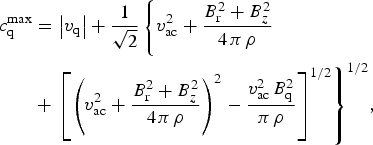
where the particular equations for the flux matrix-vectors F, P, G, and the source term Ω can be easily expressed from Eqs. (2). The maximum propagation speed of information used in the TVD-LF scheme (see Toth & Odstrcil, Reference Toth and Odstrcil1996 for details) for the LPP in an axial magnetic field case is given as:
 $$\eqalign{ c_{\rm q}^{\max} &= \left \vert {{v_{\rm q}}} \right \vert + \displaystyle{1 \over {\sqrt 2}} \left\{ {v_{{\rm ac}}^2 + \displaystyle{{B_{\rm r}^2 + B_z^2} \over {4{\kern 1pt} {\rm \pi} {\kern 1pt} {\rm \rho}}} } \right. \cr & +{\left. {{{\left[ {{{\left( {v_{{\rm ac}}^2 + \displaystyle{{B_{\rm r}^2 + B_z^2} \over {4{\kern 1pt} {\rm \pi} {\kern 1pt} {\rm \rho}}}} \right)}^2} - \displaystyle{{v_{{\rm ac}}^2 {\kern 1pt} B_{\rm q}^2} \over {{\rm \pi} {\kern 1pt} {\rm \rho}}}} \right]}^{{1 / 2}}}} \right\}^{{1 / 2}}},} $$
where index q = r, z determines the spatial direction: r for the fluxes F and P and z for the flux G calculations; v is the media velocity and v ac is the speed of sound.
Monte Carlo methods are used for modeling the radiation processes in LPPs: Laser heating (Q las), radiation transport in the plasma (Q rt), and EUV output. We simulated the evolution of the photons in full three-dimensional (3D); however, we integrated the final radiation transport results along the φ-axis in order to use these results in Eq. (2). Detailed descriptions and validations of these models in applications to laser energy deposition are given elsewhere (Sizyuk et al., Reference Sizyuk, Hassanein and Sizyuk2006b). Recently we devoted also the special topic regarding the solution of radiation transport problem in the magnetized plasma (Sizyuk & Hassanein, Reference Sizyuk and Hassanein2015). For correct modeling and higher accuracy of the radiation transport processes, we used two sets of optical opacities, that is, a general one (for full energy redistribution calculations) and a specific detailed one around the in-band region of 13.5 nm with 2% bandwidth (Sizyuk & Hassanein, Reference Sizyuk and Hassanein2013). The structure of atomic energy levels, wavefunctions, transition probabilities, ionization potentials, oscillator strengths, broadening constants, photoionization cross-sections, and other atomic characteristics are calculated using self-consistent Hartree–Fock–Slater method (Herman & Skillman, Reference Herman and Skillman1963). The collisional-radiative equilibrium (CRE) model (Zaltzmann, Reference Zaltzmann1998) is used to calculate the populations of atomic levels and the ion and electron plasma concentrations. The ion and electron concentrations calculated from the CRE model are used in the equation-of-state to predict plasma pressure and internal energy. More detailed description of plasma properties calculation can be found in (Morozov et al., Reference Morozov, Tolkach and Hassanein2004).
The heat conduction and vaporization block simulates heat transfer, melting, and surface vaporization of target (Q vap) due to radiation energy deposition (Hassanein et al., Reference Hassanein, Sizyuk and Sizyuk2008).
3. SIMULATION RESULTS
We focused our numerical modeling on a tin target because tin is currently considered the most promising material for 13.5-nm photon generation (Kumar et al., Reference Kumar, Singh and Verma2014; Roy et al., Reference Roy, Hassan, Harilal, Endo, Mocek and Hassanein2014, Reference Roy, Harilal, Hassan, Endo, Mocek and Hassanein2015). Figure 1 shows schematically the configuration of the target, laser beam, and EUV detector area where the cylindrically symmetric magnetic field is produced by two permanent magnets and is directed along the laser beam. The initial distribution of the magnetic field was calculated to be equivalent to that applied in a recent experiment (Roy et al., Reference Roy, Hassan, Harilal, Endo, Mocek and Hassanein2014), in which the expression for the off-axis magnetic field of a circular current loop was used (Knoepfel, Reference Knoepfel2000). For reconstruction of a magnetic field identical to that used in that experiment, the permanent magnets were considered as two arrays of current loops that resulted in a total magnetic field strength of ~0.5 T along the direction of plume expansion (Fig. 2a). The tin target is located at the center of coordinate system in Figure 2. Figure 2b shows a typical displacement of the magnetic during the plasma plume expansion. The frozen magnetic field moves with the plasma flow from the laser spot area towards the outside of computational domain. At the top of domain, the magnetic field is accumulated due to confinement by the impact into the permanent magnet surface.
HEIGHTS calculated magnetic field: (a) Initial distribution; (b) displacement of magnetic field by tin plasma plume at t = 100 ns, laser energy Q = 130 mJ, pulse duration τ = 5 ns, spot radius R = 40 µm.
We used in this simulation the first harmonic of the Nd:YAG laser, delivering 30 to 200 mJ in 5-, 10-, and 15-ns pulses that lead to a power density range from 4·1010 W/cm2 to 8·1011 W/cm2, with a fixed spot radius R = 40 µm. Generally, the LPP device parameters used in these simulations correspond to the experimental data published in (Roy et al., Reference Roy, Hassan, Harilal, Endo, Mocek and Hassanein2014). Initially, we compared the CEs of LPP devices obtained in our simulations with experimental data (Sizyuk & Hassanein, Reference Sizyuk and Hassanein2013b) in order to benchmark our integrated MHD modeling. Figure 3 demonstrates good agreement between experimental and simulated results for the studied LPP device. As can be seen in Figure 3, the CEs do not differ notably for the cases with (blue) and without (red) the axial magnetic field in our modeling as well as in experiments. The slight variation in experimental results can be due to measurement error.
Comparison of experimental and calculated CE of LPP device with tin target for pulse duration τ = 10 ns with (blue) and without (red) axial magnetic field (B).
We analyzed in detail the effect of the axial magnetic field on EUV source evolution and angular distribution of the EUV photon output. There is no noticeable difference in the EUV source form and size for the free-plasma plume expansion case and for the axial magnetic field used in this study (Fig. 4). The EUV output was calculated in the 13.5 ± 1% nm range and drawn as distribution of the power produced above the target surface (white dashed line) in the r–z coordinate system. This represents the total (per pulse) number of EUV photons produced in the EUV-dominated area and reaching the domain border above the target (z > 0).
Integrated EUV output area without and with axial magnetic field (B). Laser energy Q = 130 mJ, pulse duration τ = 5 ns.
Strictly speaking and theoretically, the solid angle here is more than 2π sr because the center of the EUV source is located ~20 µm above the target, but in practice we consider this value as the collectable 2π sr output. Because of the EUV collection problem, it is of interest to minimize the EUV energy absorbed by the target. These data are highly complex for measurement, and we present our calculation results as a percent of the collectable part of the EUV on the laser beam power density. As shown in Figure 5, the useful part of EUV is ~80% and increases with power density. Including the shielding effect, the layer of high-density vapor/plasma is located between the target and the EUV area and effectively absorbs the surface-directed radiation. Moreover, the absorbed EUV photons can then be re-radiated in a collectable direction. The collectable part of EUV radiation increases with laser irradiance but total EUV power declines, and these dependencies form the extreme of the CE on the irradiance axis (Sizyuk & Hassanein, Reference Sizyuk and Hassanein2007). Here we also did not observe a significant difference between the free expanding and magnetically confined cases.
The 2π sr part of total EUV output versus laser irradiance for the case with (blue) and without (red) axial magnetic field (B).
The 80/20 ratio of the “forward/reverse” EUV radiation clearly indicates the highly anisotropic character of the LPP radiation generation. In such conditions, the correct location of the EUV detector (see Fig. 1, polar angle θ) ultimately determines the validity of the experimental measurements. Regularly referring to a detector reading, researchers estimate CE by integrating over 2π sr the EUV output at the monitoring angle ~ 45°. Taking into account our integrated calculations, the experimental measurements following so approach can give both over- and/or under-estimated values, depending on detector location. Based on our HEIGHTS model, we simulated the angular dependence of the EUV output FEUV = f(θ) (J/cm2). The known distance L between the detector and the EUV source allows integration of the EUV output into 2π sr. Assume the EUV flux F i is measured at any polar angle θi. Therefore, the 2π sr EUV can be found as  $Q_{2{\rm \pi}} ^{{\rm EUV}} = 2{\kern 1pt} {\rm \pi} {\kern 1pt} {L^2}{F_{\rm i}}$ (J/2π sr). The CE into 2π sr is expressed as the ratio to the spent laser energy
 ${\rm C}{{\rm E}_{2{\rm \pi}}} = {{Q_{2{\rm \pi}} ^{{\rm EUV}}} / {{Q_{{\rm las}}}}}$.
Figure 6 shows that detector placement at various θ-angles gives the final CE2π difference by a factor of 2, with the growth to the target normal direction (Morris et al., Reference Morris, Hayden, O'Reilly, Murphy, Dunne and Bakshi2007). However, it is clear that the correct value of the CE2π can be calculated by simple summation of all EUV photons that escaped the computation domain above the target surface. In addition, this can be done by direct integrating of the registered fluxes F i. We found that the correct location (where the measured EUV flux corresponds to the averaged value after the correctly integrated angular distribution) does not depend on the laser irradiance and is equivalent to 60°. We consider this conclusion an important result for correspondence between the experimental measurements and calculations. The correct polar angle to best measure the CE is indicated in Figure 6 by the vertical red dashed line. To avoid overloading the figure, magnetic-field cases are excluded here. The magnetic and free cases curves are very close to one another.
Measurement of CE versus EUV flux monitoring angle. Red dashed line marks correct polar angle.
Our calculation data and analysis indicate weak influence of the external axial magnetic field directly on the processes of EUV generation, on the EUV source form and size, and on the plasma parameters close to the target surface. However, the axial magnetic field displacement (see Fig. 2b) should introduce some changes into the laser plasma behavior during the expansion. These changes should become apparent in the later phase of the plasma plume expansion and farther from the target surface, where the hydrodynamic forces of the plasma motion become comparable with the magnetic forces. Figure 7 shows the tin ion energies in front of the plasma shock wave in the axial direction. As in previous figures, the blue curve represents the magnetic field case. One can see the slight spreading of the ion shock wave and decreasing of the ion energy peak after 50 ns of the plume expansion in the axial magnetic field. Distance to target surface is ~4 mm at this moment. The shock-wave ions decelerate and transfer energy in front of the magnetic field.
Tin ion energy distributions along z-axis at various time points with and without magnetic field (B). Laser energy Q = 130 mJ, pulse duration τ = 5 ns.
Because the hydrodynamic forces are determined with hydrodynamic pressure and the magnetic forces grounded on magnetic pressure, we compared these values at selected time points. Figure 8 clearly confirms our prediction regarding the magnetic field effect. At 5 ns (directly after the laser beam impact), the magnetic pressure is much lower than the hydrodynamic pressure on the shock-wave front. This difference becomes large at the target surface, that is, in the EUV source area due to the magnetic field displacement. The blue and red curves show comparable values after the 20 ns of free plume expansion. At about 50 ns, the magnetic pressure becomes higher than the hydrodynamic pressure and the ions begin active deceleration. Comparison of the magnetic and thermal parts of pressure is presented in Figure 8 for the above mentioned time points. Initially, the thermal pressure at the target surface is about 1010 Pa that is five orders of magnitude higher than magnetic pressure in this experiment. Free plasma expansion leads to the decreasing of the hydrodynamic pressure at the front of cloud. The thermal pressure decreases to 105 Pa in 50 ns at the ~0.5 cm distance from the target surface and becomes similar to magnetic pressure. After this time point, we observe the difference in plasma dynamics for the non-magnetic and magnetic cases that explains the difference in front ions energy. The 0.5 cm is the minimal distance where the plasma dynamics can be controlled at the given experiment conditions. We estimated the external magnetic field value required to change the EUV area (1010 Pa in Fig. 8) to be in the range of 150–200 T, depending on the magnetic field displacement effect, which is unrealistic for such experiments.
Comparison of hydrodynamic (red) and magnetic (blue) pressures in expanding laser plasma. Laser energy Q = 130 mJ, pulse duration τ = 5 ns.
Therefore, we can conclude that based on our present modeling, the external axial magnetic field can be used for accelerated-ion damage mitigation but not for control or confinement of the EUV source area. The influence of the ~0.5 T magnetic field on plasma dynamics and accelerated ions becomes noticeable at distances of ~5 mm from the laser spot. We suppose that effective control of plasma plume expansion should not be based on the permanent magnetic field but rather on the magnetic field gradients, that is, on the time-varying magnetic fields as a magnetic pinch. The prospective direction for future work is application of a Z-pinch technique for laser plasma confinement. The azimuthal magnetic field can be applied for the prevention of plasma plume expansion and for confinement of the EUV source area. We are considering such a study for our future work, especially for the radiation generation and transport areas.
4. CONCLUSIONS
We have developed integrated comprehensive models for accurate simulation of LPP and laser/target interaction in an external axial magnetic field. Based on our constructed physical and mathematical model, the HEIGHTS computer package for LPP was upgraded and benchmarked by comparison with previous experimental data. Along with resistive MHD calculations, the integration included the radiation transport module that now allows full 3D radiation flux simulations in which radiation spectra with fine details and transport are used. The developed package was applied to study the angular distribution of the EUV output of an LPP device with tin planar targets in the presence of external axial magnetic fields.
We found that the external magnetic field of 0.5 T we used in recent experiments is not strong enough for EUV source enhancement or modification. We showed that only expanded plasma could be deviated by the applied axial field due to comparable thermal and magnetic pressures. We predicted the minimum distance where the plasma dynamics can be controlled at the given experimental conditions. The axial fields can be used for possible ions mitigations system by taking into account such distance. Analysis of the angular distribution of EUV output showed strong anisotropy. Therefore, a EUV detector placed at various polar angles could result in variation by a factor of 2 of the estimated CE. We found that the correct monitoring angle (where the measured EUV flux corresponds to the averaged value after the correctly integrated angular distribution) does not depend on laser irradiance in the studied range and is equivalent to ~60° rather than the 45° commonly used. We recommend arranging the EUV sensors at this angle in any EUV experimental measurements with such devices. More effective control of plasma plume expansion should not be based on the permanent magnetic field strength but on the magnetic field gradients, that is, on the time-varying magnetic fields as a magnetic pinch.
ACKNOWLEDGMENT
This work is supported by the National Science Foundation, PIRE project.



