I. INTRODUCTION
Generally, the automobile weight can be effectively reduced, and the performances of different parts will still be maintained through connections of different types of materials. Reference Staeves1 High-strength steel has been widely used in the design of automobile parts in recent years. Reference Jia, Yang and Ni2 However, there are many technique difficulties when welding together high-strength steel and original material. Reference Shah and Ishak3–Reference Lin, Cui and Lu5
Transformation-induced plasticity (TRIP) steel is a novel generation of high-strength steel, which has the greatest potential applied in the field of lightweight automobiles. Moreover, the TRIP high-strength steel is fabricated by increasing carbon, manganese, silicon, etc. It has poor weldability since during welding process between TRIP high-strength steel and other steels, severe segregation hardening and joint nugget interface brittle fracture occur. The superiority of TRIP steel requires that automobile manufacturers urgently solve its welding problems. Some investigations have been conducted on TRIP high-strength steel welding. Reference Hernandez, Okita and Zhou6,Reference Vasilakos, Ohlert and Giasla7 The nugget diameter of the resistance spot welding joint of TRIP590 high-strength steel is an important factor to influence the joint fracture characteristics. Reference Park, Lee and Choi8 The formation of brittle martensite in the heat-affected zone (HAZ) may decrease the toughness of the joint of TRIP800 high-strength steel by CO2 laser welding. Reference Perez-Medina, Lopez and Reyes-Valdés9
As previously reported, the welding process and mechanical properties of the joints were investigated. The optimal welding parameters of resistance spot welding of TRIP800 high-strength steel have been obtained.
Reference Yu, Wang and Yang10
The nugget diameter of TRIP800 high-strength steel resistance spot welded joint should be at least
 $4.5\sqrt T$
(where T is the thickness of steel plate) so that the joint can satisfy the standard of shear tensile strength.
Reference Ertek and Ramazan11
The mechanical properties and process characteristics of resistance spot welding and fiber laser welding joints based on TRIP980 high-strength steel plates (TRIP980) were compared.
Reference Wei, Liu and Lv12,Reference Wei, Liu and Lv13
However, the above investigations involved the welding of 590–980-MPa strength grade of TRIP high-strength steel. There are no reports on the welding of TRIP980 and other steels. The lag of welding technology restricts the large-scale application of TRIP980 in the field of automobile manufacturing. To satisfy the design requirement of multimaterial lightweight automobile structures, the welding problem of TRIP980 with other steels should be solved immediately.
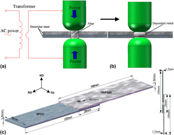
Resistance plug welding (RPW) was first proposed by Luo. Reference Feng, Luo and Li14 The welding of 7075 aluminum alloy has been successfully realized by RPW, and the joint is stronger than that obtained by ordinary resistance spot welding. However, there are almost no related detailed reports on the welding of steels by RPW; more importantly, we first used the RPW technique for the welding of steels in the present research, and we aim to choose the appropriate welding parameters to enhance the weldability of the final joint. RPW as a hybrid welding technology is shown in Fig. 1(a) and 1(b). The basic principle is that the metallic filler with excellent weldability is placed in the reserved hole between two kinds of materials. The filler is subjected to resistance heating. Both ends of the filler material are flattened as deposited metal. The filler material is fused into the joint, and the metallurgical bonding is ultimately realized between the filler material and the base material. This process usually has two characteristics: mechanical connection of the rivet and metallurgical bonding of resistance spot welding.
Illustrated diagrams of the RPW. (a) Schematic diagram. (b) Appearance of joint. (c) Lap schematic diagram of dissimilar steels.

In our present work, the dissimilar steels were firstly and firmly connected by RPW. In view of the fact that the filler has an important influence on the strength of the RPW joint, we attempted to use an orthogonal test to explore the optimum process parameters of RPW for the TRIP980 and SPCC low-carbon steel plates (SPCC). Meanwhile, the structure and fracture characteristics of RPW joint were investigated, which will enrich the RPW theory and extend the heterogeneous RPW application in industry.
II. EXPERIMENTAL WORK
A. Base material
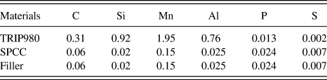
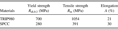
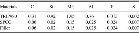
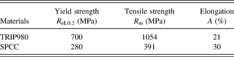
The adopted materials of cold-rolled TRIP980 and SPCC were provided by ANSTEEL and BTSTEEL, respectively. The composition and the mechanical properties of the two types of steel are shown in Tables I and II, respectively. Sample sizes are about 100 × 28 × 1.5 mm; overlapping was conducted as shown in Fig. 1(c). Considering the head size of the electrode and melt nuclear expansion space, the diameter of the hole is smaller than the electrode head terminal diameter. According to the principle that the welding of the same material is more flexible, the composition of the filler is consistent with SPCC, and the diameter of the filler is almost identical to the diameter of the hole.
Composition of base metals.
Mechanical properties of base metals.
B. RPW
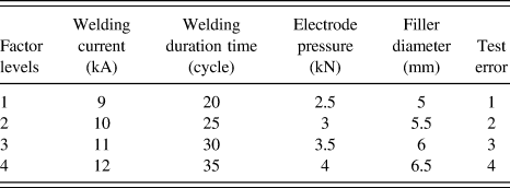
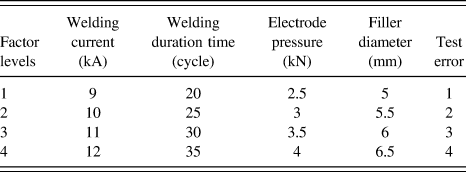
DN-50B (Changzhou Jun Hong Machinery Co., Ltd. Changzhou City, China) power frequency resistance spot welder was adopted in practical tests. The maximum power output of the welder is 50 kVA, and the diameter of the electrode head is around 8 mm. We selected the parameters directly related to the welding heat input of the joint, welding current, welding duration time, electrode pressure, and filler diameter. Compared to the effects of other factors, the error column was introduced using the orthogonal test table L16 (45) to design the experiment. Table III lists the orthogonal test factors and levels.
Factors and levels of orthogonal test.
C. RPW experiments
It is necessary to remove the oxide films of the upper and lower surfaces using sandpaper before welding. Their surfaces were cleaned, and then the RPW experiment was carried out. As the same size of cylindrical filler was placed in the reserved through hole, the filling material needs to have no inclination and keep the same length on both terminals. After completion of welding, we took the cross-section of RPW joint to make metallographic, EDS (energy-dispersive spectroscopy), and EBSD (electron backscattering diffraction) specimens. Zeiss metallographic microscope (Carl Zeiss AG, Shanghai, China) was used to observe the cross-sectional microstructure of the RPW joint. EBSD samples are needed to be polished after mechanical grinding. The grain shape and texture of the welding layer were observed using SUPRA55SAPPHIR (Carl Zeiss AG, Shanghai, China) electron backscattering diffraction system assembly in a Zeiss field-emission electron microscope (Carl Zeiss AG, Shanghai, China). We also used MTP-1A-type double electrolytic jet, Bo Yi reduction, and 5% per-chloric acid and 95% methanol (volume fraction) electrolyte to thin the TEM sample of the RPW joint. The experiment temperature was −25 °C, and the voltage was 15 V. The X Stress 3000 analyzer (Stresstech Oy, Vaajakoski, Finland) was applied to measure the transverse residual stress of the RPW joint. A microcomputer was used to control the electronic tensile testing machine, and a micro-hardness instrument was utilized to analyze the shear tensile loading and hardness of the RPW joint. Considering that the tensile sample on both sides of the plate is not on a central line, a gasket of the same thickness on both sides of the sample was adopted to ensure test reliability, and then adopted the S-3400 SEM (scanning electron microscope; Hitachi, Tokyo, Japan) to observe the fracture microstructure of the joint after the shearing tensile study.
III. RESULTS AND DISCUSSION
A. Orthogonal experiment analysis
1. Range analysis of the RPW parameters
Based on the orthogonal experiment, Table IV lists the shearing tensile loading and the appearance of melt nuclear with the different factors and levels. k n (specifically, n = 1–4) is the average value of shear tensile loading corresponding to the welding current, welding duration time, electrode pressure and the filler diameter in the n levels of tests. k 1 is the average value of all the test results that corresponds to factor level number 1, k 2 is the average value of all the test results that corresponds to factor level number 2, etc. The range represents the same factors at different levels (n = 1–4) or the difference between the maximum and minimum values.
Orthogonal test and range analysis of joints.

We deduced the primary and secondary factors that affect RPW joint shearing tensile loading as the evaluation index in contrast to k numerical value and the range size in each column of Table IV. Welding current, filler diameter, welding duration time, electrode pressure, the testing error, and the range are all less than the factor range, and the test error seems to be smaller. Also, it means that the shear tensile loading of number 7 is the largest of the 16 groups of samples, and its failure loading is about 11.766 kN, so the welding parameters of sample 7 are the optimized process parameters. The corresponding welding parameters are as follows: welding current of 10 kA, filler diameter of 5 mm, welding duration time of 30 cycles, and electrode pressure of 4 kN. Meanwhile, the solder joint was formed with uniform appearance, and the melt nucleus had excellent consistency.
The four kinds of filler sizes selected were carefully compared with the numerical value k of the fillers diameter. When the diameter of the filler is 5.5 mm, the failure loading is larger than that at other diameters. It can be affected by the diameter size of the end face of the electrode head and the plate thickness. RPW has a theory on fusion nuclear diameter: as the filler diameter is smaller than the nuclear diameter, the final formation of the deposited metal “rivet” is so thin, it affects the joint strength; and when the filler diameter is bigger than the nuclear diameter, the filler and two kinds of base metal are not fully fused. This case is just a single rivet connection; it cannot bring the advantages of the RPW head in metallurgical combination and also goes against the enhancement of joint strength.
2. Variance analysis of the RPW parameters
Table V shows the results of the variance analysis. F reflects the influence of various factors on the size of the results. Based on the F distribution, the various factors F α can be obtained.
Variance analysis and statistics.

Note: * represents the significant in the table.
Firstly, we chose a significance level of α = 0.05. The comprehensive analysis of the F value, compared with the F α critical value given in the above table, the influence of welding current, filler diameter, welding duration time, and electrode pressure on the shearing tensile loading of RPW joint gradually declined. The F value of the welding current, filler diameter, and the welding duration time were larger than the given maximum F α critical value. The variance analysis results are consistent with the range analysis.
B. The microstructure analysis
1. Base metal microstructure
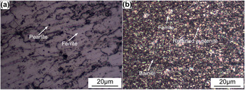
Figure 2 shows the microstructure of two types of base materials. SPCC is composed of ferrite and pearlite, while TRIP980 is composed of ferrite, bainite, and residual austenite.
Microstructure of base metals. (a) SPCC. (b) TRIP980.

2. Joint microstructure
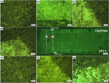
Accordingly, we got the optimal welding parameters in our previous research work from an orthogonal experiment, and the optimal welding parameters are as follows: welding current of 10 kA, filler diameter of 5 mm, welding duration time of 30 cycles and electrode pressure of 4 kN, and the failure loading is 11.766 kN. To further analyze the performance, the optimal welding parameters were used to obtain several welding joints. Figures 3(a)–3(g) shows the macroscopic morphology and micrographs of the RPW joint of TRIP980 and SPCC with the optimum parameters. RPW joint also contains an oblong nugget and heat-affected zone (HAZ). The filler was raised in the middle position. The deposited metal circle before welding position #1 is extended to position #2 combined with the surface for filling material and two kinds of base metal fusion zones. Figure 3(a) (corresponding to position a) and Fig. 3(e) (corresponding to position e) show that the TRIP980 side and the SPCC side were filled with the microstructure of HAZ. The microstructure of the two regions is consistent. It is mainly owing to the low-carbon steel filler in the thermal resistance of the heating process. The heat is less beyond the external surface, and heat dissipation undergoes fast; thus, ferrite and pearlite were formed. Figure 3(b) (corresponding to position b) and Fig. 3(f) (corresponding to position f) show microstructures on the TRIP980 filler rivet in the fusion zone and SPCC filler rivet in the fusion zone. The two regions are far away from the center of the nugget. SPCC and the rivet implement perfect fusion, and the fusion zone boundary is almost indiscernible, but the fusion zone of TRIP980 with a filler rivet on both sides is obvious. There is an obvious difference between TRIP980 and the alloying components of the filler. The mixing zone mainly consists of austenite, and acicular ferrite was formed because the diffusion of the alloy elements cannot be completed for the less heat. Figure 3(c) (corresponding to position c) and Fig. 3(g) (corresponding to position g) show the areas near the fusion core of the TRIP980 side and near the fusion zone of the SPCC side of the fusion zone microstructure, respectively, mainly for the needle-like martensite. Figure 3(d) (corresponding to position d) shows the structure of the combined surface of three-type materials (TRIP980/SPCC/filler). The microstructure of the three-type materials in the fusion zone is more complicated and mainly contains martensite, a small number of ferrite and bainite. The filler/SPCC fused better with the surface. Since the two base compositions are consistent, the region is mainly an austenite coarse-grained zone and fine-grained zone. The filler/TRIP980 bonded surface is also influenced by the welding thermal cycle and the fusion nuclear expansion. According to the microstructure characteristics of the welding zone, there exists an obvious metallurgical bonding between the filler and the base material.
Microstructure of the RPW joint as the processing parameters are welding current of 10 kA, filler diameter of 5 mm, welding duration time of 30 cycles, and electrode pressure of 4 kN.

C. EBSD and EDS of the joint
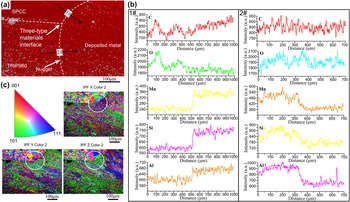
Figures 4(a) and 4(c) shows the grain orientations and alloy composition of the junction surface of the RPW joint. Figure 4(b) shows the detection results of EDS in different regions of RPW joint. The concentrations of Si, Mn, and Al were increased from the SPCC to the filler, but the O and C concentrations were nearly unchanged. The concentrations of Si, Mn, and Al were decreased from the TRIP980 to the filler, but the concentrations of O and C were also unchanged. This also means that the diffusion of the interstitial atom C is more than that of other solute elements, and the C diffusion is more adequate. There are no carburization and decarburization layers in the detection region, indicating that the rigidity tendency is slight, which is consistent with previous metallographic microscopic analysis and fracture scanning results. From the above analysis, SPCC before welding and the composition of the deposited metal are consistent, but Si, Mn, and Al have concentration gradients after welding. The concentrations of Si, Mn, and Al in the filler are slightly more than that of SPCC, and the three components diffuse from TRIP980 into the filler. From component diffusion theory, we can decide that the three-type materials are in metallurgical combination.
Grain orientation and main components of the combination surface fusion zone of the RPW joint as the processing parameters are welding current of 10 kA, filler diameter of 5 mm, welding duration time of 30 cycles, and electrode pressure of 4 kN. (a) Detection area and detection path. (b) Detection results of EDS. (c) Detection results of EBSD.

According to the results obtained above, the different sizes, colors, or brightness values of grains exist in the RPW joints. The junction surface has no obvious preferred orientation. The grains cross each other at the three-type materials intersections. There is no obvious interface boundary between TRIP980 and the deposited metal. The grain direction and size are almost unanimous.
D. TEM characterization of the interface of the welds
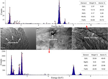
To study the microstructure of the micro-phase and crystal defects of the RPW joint, the fusion zone was observed and analyzed using TEM. Figure 5 shows the microstructure morphology of the fusion zone at three-type materials interface (TRIP980/SPCC/filler) and the testing results of the TRIP980. Figure 5(a) is the interface fusion zone. After the sample is corroded by the electrolyte, the different directions of lath martensite were observed around corrosion. The observed results are consistent with the previous observations in Fig. 3(d). Figure 5(b) illustrates that the inclusion in the fusion zone and its size is about 400 nm. The fusion core is expanded in the process of formation, and the intermetallic compound brittle phase is formed by atom diffusion and bonding. Figure 5(c) shows the interface observed in the fusion zone. The width of the phase interface is between 100 and 150 nm. A “river pattern” of the uneven deformation layer is observed on both sides of the organization. EDX was used to study the phase interface, precipitates, and microscopic structure characteristics of inclusions. The elements and the contents of the phase interface region are F, 13.13%; O, 2.37%; Mn, 0.33%; and Si, 0.17%. The alloy elements and their contents of inclusion are O, 33.04%; Al, 25.87%; Fe, 24.55%; and Mg, 9.44%. EDX test shows that the phase interface and slag inclusions are mainly C, Mn, Si, Al and other alloy oxides.
TEM information of the interface fusion zone of three-type materials in the RPW joint as the processing parameters are welding current of 10 kA, filler diameter of 5 mm, welding duration time of 30 cycles and electrode pressure of 4 kN. (a) Microstructure of the fusion zone. (b) Inclusion of the fusion zone. (c) Phase interface of fusion zone.

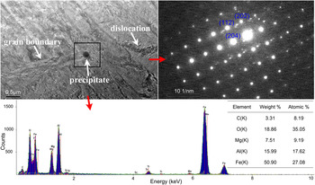
To analyze the alloy composition of the precipitates further in the combined surface of three-type materials, the relationship between the micro-phase analysis and grain orientation was determined. Figure 6 shows the micro-phase in the fusion zone. There also exists some dislocation at the grain boundary, and there are small particles that precipitated in the dendrites, and the precipitation size is 0.25 μm. EDX results show the main alloying elements, and the contents of the precipitates are O, 18.86%; Al, 15.99%; Mg, 7.51%; Fe, 50.9%; and C, 3.31%. From an analysis of the diffraction spots of the precipitates, the interfacial precipitates are mainly intermetallic compounds of Al2O3 and MgAl26O40, which contains a trace amount of Si and F. In the Fe–Al–O series of compounds, the reason for the formation of Al2O3 is the lowest free energy, due to the presence of a large number of Al atomic vacancies in the Al2O3 direction; the Al atom diffusion velocity along the direction and the growth rate are relatively larger.
EDX component detection for the fusion zone of three-type materials in the RPW joint when the processing parameters are welding current of 10 kA, filler diameter of 5 mm, welding duration time of 30 cycles and electrode pressure of 4 kN.

E. Mechanical properties of RPW joint
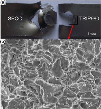
Figure 7 shows the macro-view fracture and the fracture characteristics of the RPW joint. The base material on the SPCC side has a slight neck shrinkage; the fracture position of the joint occurs in the respective HAZ rather than in the combination surface fusion zone of the three-type materials. The joints are always broken at the weakest connection position. The strength of the fusion zone is larger than that of the HAZ. The gradient is lower as the shear tensile loading reaches the maximum, which is the typical shear tensile ductile fracture mode and not the brittle fracture. Fracture scanning results present a large number of toughening nests, and the toughening nest has obvious tear edges, namely, ductile fracture, and the scanning results are consistent with the shear tensile testing.
Mechanical properties of RPW joint as the processing parameters are welding current of 10 kA, filler diameter of 5 mm, welding duration time of 30 cycles, and electrode pressure of 4 kN. (a) Macro-view of fracture. (b) Fracture morphology.

F. Residual stress analysis of RPW joint
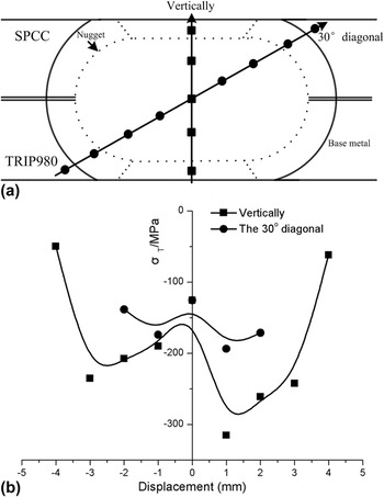
As the thermal conductivity and linear expansion coefficient of TRIP980 are different from that of SPCC, the factor of the welding residual stress should be considered. The residual stress in the cross-section of RPW joint was determined using an X-ray stress analyzer. Figure 8 shows the position and the results of the residual stress in the cross-section of the RPW joint; the residual stress curve along the horizontal and 45° directions from SPCC to TRIP980 increases first and then decreases and again increases and decreases afterward.
Test positions and distributions of residual stress in the RPW joint as the processing parameters are welding current of 10 kA, filler diameter of 5 mm, welding duration time of 30 cycles and electrode pressure of 4 kN. (a) Test positions. (b) Distributions.

Both “a” and “e” positions in Fig. 3 of the previous section are under the pressure of the electrode head and the restraint from the through hole. The residual stress in the RPW joint is compressive stress, which is larger on the TRIP980 side than on the SPCC side because the plastic deformation and expansion are produced while the filler is heated during the welding process. Metal can move to the area of minimum free energy, and the margin part of both sides of the filler is pressed into the rivet. The residual stress is relative to the thermal expansion coefficient and thermal conductivity of the welded joint, and the residual stress on the SPCC side is smaller than the TRIP980 side because of the same strain rate and thermal expansion coefficient of the same material, and the strain rate and the thermal expansion coefficient of the filler are greater than TRIP980. Along with the welding heat input and the removal of the electrode pressure, although the deposited metal solidified, the temperatures of the TRIP980 and SPCC base metal decreased rapidly, and the restraint of the deposited metal to the two base metals decreased, which can lead to the decrease of the compressive stress in the two base materials. However, as can be seen in position “d”, three-type materials interface is ultimately for the expansion of state; it also can be inferred that the deposited metal of the two base materials still constrained deformation state. Therefore, the SPCC base metal residual stress reduced, yet compressive stress still exists. As seen in Fig. 3 of the previous section, the RPW deformation is small and nonconcave; the residual compressive stress cannot cause the residual stress deformation, and the pressure of the residual stress in the tensile shear can greatly offset a part of the tensile stress, which is one of the reasons for the improved mechanical properties achieved by the RPW.
Fatigue performance is an important index in the structural design of automobile parts. Reference Zhao and Yu15 In the future, we will continue to study the connection of dissimilar steel by the RPW from the aspects of fatigue properties.
IV. CONCLUSIONS
In summary, we can draw the following conclusions:
-
(1) According to the orthogonal experiment method, the welding parameters of dissimilar steel RPW of TRIP980 and SPCC influencing the shear tensile failure loading are welding current, filler diameter, welding duration time, and electrode pressure. The optimal welding parameters are 10 kA, 5 mm, 30 cycles, and 4 kN, respectively, and the fracture of the RPW joint is ductile fracture.
-
(2) Dissimilar steel RPW joint is composed of a rounded rectangular nugget zone and transition zone; the alloy including C, O, Si, Mn, and Al among TRIP980, deposited metal, and SPCC displayed different degrees of diffusion. Both the filler and the two types of base metals achieve a firmly metallurgical combination.
-
(3) With the optimal welding parameters, it seems to have no severely preferred orientation in the RPW joint. There is also no obvious interface boundary as three-type materials grains intersect each other between TRIP980 and the deposited metal. Grain direction and size are almost the same.
-
(4) Inner residual stresses of the RPW joint are compressive stresses, which is beneficial to an increase of shear tensile loading.
ACKNOWLEDGMENTS
TRIP980 of this research was supported by ANSTEEL.