I. INTRODUCTION
In the past few decades, conductive polymers have attracted considerable attention due to the important role they play in electromagnetic interference (EMI) shielding and microwave absorption technologies.Reference de Chanterac, Roduit, Belhadj-Tahar, Fourrier-Lamer, Djigo, Aeiyach and Lacaze1 Among the conducting polymers, polyaniline (PANI) is perhaps the most versatile because of its easy and inexpensive preparation methods and also its desirable properties, such as thermal and chemical stability, low specific mass, controllable conductivity, and high conductivity at microwave frequencies.Reference Sudha, Sivakala, Prasanth, Reena and Radhakrishnan Nair2 It has been demonstrated that these physical properties are usually closely related to the particle shape, independent of size.Reference Sun, Guo, Yang, Zhou, Cui, Liu and Zhao3 So, lots of methods to control the morphology of PANI, for example, electrochemical methods,Reference Weng, Lin, Chen and Zhou4 anodized alumina template,Reference Choi, Kim, Lee, Lim, Lee and Ja Kim5 physical methods,Reference Yang, Zhu, Hou, Xu and Wan6 and soft template,Reference Svelko, Reynaud and Françoi7–Reference Srinivasan and Amalraj10 have been used in the preparation of PANI nanofibers, nanowires, rods, and tubes.
PANI microtubes with moderate conductivity and dielectric property should be an excellent microwave absorbing and EMI shielding material, but very little has been reported on their synthesis and properties. On the other hand, silver is an attractive material because it exhibits high electrical and optical properties for applications in catalysis, electronics, photonics, and photography.Reference Li, Gao, Murphy and Caswell11, Reference Maillard, Giorgio and Pileni12 Especially, as interconnects or active components in fabricating micro/nanodevices, silver microrods may provide an ideal system for experimentally probing physical phenomena such as quantized conductance and localization effects. However, to the best of our knowledge, new functional nanomaterials of silver microrods have not been reported.
Here, a novel synthesis method of PANI microtubes was developed. This method shows an easy processing and does not need any template to attain final microtube products. In addition to this, the silver microrods are of great interest, which exhibit a wide range of electrical and optical properties. Therefore, the silver microrods were further prepared and studied.
II. EXPERIMENTAL
A. Chemicals
Aniline monomer was distilled under reduced pressure and stored below 0–8 °C. All other reagents were of analytical grade and used without further purification, including ammonia persulfate (APS), toluene-p-sulfonic acid (TSA), dimethylformamide (DMF), and other reagents. All chemicals were purchased from Shanghai Chemical Reagents Co.
B. Synthesis of PANI
PANI microtubes were successfully synthesized via a self-assembly process assisted by excess APS as follows: 4.6 g aniline and 8.5 g TSA (or 36 mL HCl 1mol/L) were dissolved in 35 mL aqueous solution with stirring at room temperature. The mixture was then cooled to about 0–5 °C in an ice bath, followed by addition of 25 mL APS aqueous solution (0.42 g/mL) as an oxidant. The mixture was allowed to react for 4 h. then, the pure products were obtained by centrifugation.
C. Preparation of silver microrods
First, 0.15 g PANI microtubes was mixed in 30 mL DMF solution under vigorous stirring. Then, 10 mL AgNO3 DMF solution (0.1 g/mL) was directly added into the above solution. The resulting mixture was kept under continuous stirring at 40 °C for 24 h. At last, the purification procedure was carried out by centrifugation.
D. Characterizations
Scanning electron microscopy (SEM) measurements were performed on a SHIMADZU SU-150 0 microscope (Kyoto, Japan). Transmission electron microscopy (TEM) measurements were performed on a Philips CM 120 electron microscope (Amsterdam, Netherlands). Infrared spectra of KBr powder-pressed pellets were recorded on a BRUKER VECTOR22 spectrometer (Bremen, Germany). The surface plasmon resonance was measured by a UNICAM UV300 UV–vis spectral instrument (Waltham, MA). X-ray diffraction (XRD) patterns were obtained with a Siemens D5005 diffractometer (Bremen, Germany) using Cu Ka radiation. The standard four-probe technique using a Keithley 797A instrument (Nanjing, China) was used to measure the electrical conductivity of a pellet made with each PANI sample.

PANI and its composite in toroidal form were measured using a microwave vector network analyzer Anritsu Angilent 8510c (Nanjing, China) from 0 to 6000 MHz.
III. RESULTS AND DISCUSSION
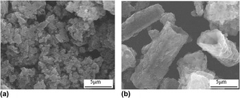
SEM was used to characterize the morphology of PANI containing various doped agents. As shown in Fig. 1(a), the products exhibit irregular morphology with an average diameter of about 1.0 μm in the presence of the doped agent (HCl). As being prepared in the presence of TSA, the irregular particles moved into microtubes with an average diameter of about 3.0 μm and a length up to 12.0 μm [Fig. 1(b)]. The aspect ratio of the long tubes is around 3–4. The result indicates that the doped agent strongly affects the morphology of PANI. These results indicate the formation of PANI microtubes by the simple method.
Scanning electron microscopy (SEM) images of PANI products containing various doped agents: (a) HCl and (b) toluene-p-sulfonic acid (TSA).

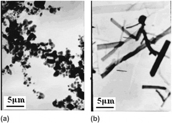
To further confirm the formation of PANI microtubes, the structure of the products was further characterized by TEM, as shown in Fig. 2. In Fig. 2(b), the internal cavity of the PANI microtube is easily visible in TEM micrographs, in which the average size is almost consistent with the results of SEM image, while Fig. 2(a) shows irregular particles. These results further strongly indicate the formation of PANI microtubes.
Transmission electron microscopy (TEM) images of PANI products containing various doped agents: (a) HCl and (b) TSA.

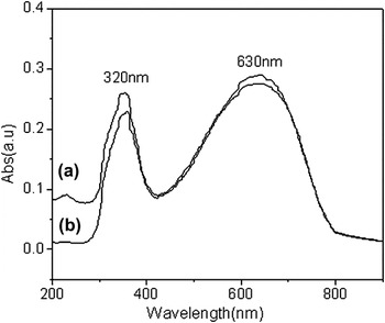
The UV–vis spectra of PANI containing various doped agents were compared as shown in Fig. 3. It shows that the two absorption bands appeared in the UV–vis spectra of PANI solution in DMF. The first absorption band with maximum at approximately 320 nm is associated with the π–π* transition of the conjugated ring systems, and the second band at approximately 630 nm is assigned to benzenoid to quinoid excitonic transition.Reference Sarno, Manohar and MacDiarmid13 This result suggests that these microtube products are PANI. These results show that the effect of PANI morphology on the UV–vis spectra is slight, which is consistent with pervious works.Reference Sarno, Manohar and MacDiarmid13, Reference Rahy and Joo Yang14
Ultraviolet–visible (UV–vis) spectra of PANI products containing various doped agents: (a) HCl and (b) TSA.

Fourier transform infrared (FTIR) spectra of PANI containing various doped agents are shown in Fig. 4, and no significant difference is observed between the two samples. The bands at 1590 and 1495 cm−1 are related to the quinonoid and the benzenoid structures, respectively.Reference Huang and Lin15 The bands at 1300 and 825 cm−1 are assigned to the CN stretch of a secondary aromatic amine and aromatic CH out-of-plane bending, respectively.Reference Huang and Lin15 These results further suggest the formation of PANI, while the FTIR spectra of PANI are regardless of their morphologies, too.
Fourier transform infrared spectra of microtubes products containing various doped agents: (a) HCl and (b) TSA.

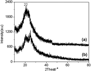
XRD patterns of PANI containing various doped agents are shown in Fig. 5. It shows one peak approximately at 22°, which is consistent with the result in previous works.Reference Sun, Guo, Yang, Zhou, Cui, Liu and Zhao3, Reference Sarno, Manohar and MacDiarmid13 It is interesting that the XRD pattern of PANI containing TSA shows two peaks, as shown in Fig. 5(b). A similar result has been observed for PANI rodlike structure,Reference Sun, Guo, Yang, Zhou, Cui, Liu and Zhao3 which further confirms the formation of PANI microtubes. From these results, we can also draw the conclusion that our samples, regardless of their morphologies, are amorphous.
X-ray diffraction (XRD) of PANI products containing various doped agents: (a) HCl and (b) TSA.

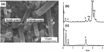
In addition, silver microrods were further prepared using the PANI microtubes as templates, and their formation was confirmed by the SEM image, as shown in Fig. 6. Figure 6(a) clearly shows a three-dimensional microstructure with rod shape. The average diameter of the microrods ranges from 2.0 to 4.0 μm, and the length can reach 10.0 μm under a typical experimental process, which is almost consistent with the size of PANI microtubes. The result indicates the formation of silver microrods inside PANI microtubes. Above result is further confirmed by the energy-dispersive x-ray spectra (EDX) pattern, as shown in Figs. 6(b) and 6(c). The EDX pattern of inside microrods [Fig. 6(b)] shows the C, O, N, S, and Ag elemental signatures in the composite particles, in which the content of silver is about 94.0 wt%. The small amount of C, O, S, and N (approximately 6.0 wt%) is assigned to the TSA-doped PANI. Contrarily, the EDX pattern of outside microrods shows large amount of C, O, S, and N (approximately 98.5 wt%) assigned to the TSA-doped PANI, and the Ag elemental signature is not observed. These results strongly indicate the formation of silver microrods inside PANI microtubes.
(a) SEM image and energy-dispersive x-ray spectra of the (b) inside and (c) outside silver microrods.

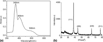
The formation of silver microrods was further confirmed by the UV–vis absorption spectrum and XRD as shown in Figs. 7(a) and 7(b), respectively. As shown in Fig. 7(a), comparing with pure PANI microtubes, there is a new absorption peak at 409.0 nm, which can be assigned to surface plasmon resonance of the Ag nanoparticles.Reference Sun, Yang, Cai, Liu, Zhao and Zhang16 In addition to this, Fig. 7(b) shows several diffraction peaks at about 38°, 44°, 64°, and 77°, corresponding to the (111), (200), (220), and (311) planes of the cubic phase of Ag, respectively.Reference Sun, Guo, Yang, Zhou, Liu and Zhao17 These results further indicate the formation of silver microrods.
(a) UV–vis spectrum and (b) XRD of the silver microrods.

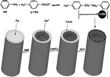
Scheme 1 shows the formation of PANI microtubes prepared by the in situ self-organization process. For this process, we used organic acid (TSA) instead of conventional strong acid HCl. TSA serves both as an effective doping agent and as a structure-directing agent due to its amphiphilic structure because of the hydrophilic –SO3H group and lipophilic C7H8 chain.Reference Reddy, Sin, Ryu, Noh and Lee18 In addition, aniline is hydrophobic.Reference Reddy, Sin, Ryu, Noh and Lee18 When aniline is added dropwise to the aqueous solution of TSA, the –SO3H group of TSA reacts with the –NH2 group of aniline through an acid–base interaction, and this results in the formation of micelles with microtube structure. Generally, the microtube crystals of the aniline/TSA complexes were commonly broken into spherical particles at low reaction temperatures (<5 °C).Reference Sun, Guo, Yang, Zhou, Cui, Liu and Zhao3 So, the PANI spherical particles are prior to formation as shown in lots of works.Reference Rodolfo, Jorge, Jose, Antonio, Eduardo, Ivana and Erika19, Reference Kan, Zhou, Zhang and Patel20 Here, the different result is attributed to large amount TSA stabilizing the PANI microtube by hydrogen bonding and ionic interactions. That is why the microtube continues to grow without any guide and with an internal cavity determined by nucleus size. Furthermore, the PANI microtube aggregates can adsorb the Ag+ ion by the –SO3H group of TSA. As shown in Scheme 1, the –SO3H group of TSA tends to be inside PANI microtube. So, the silver microrods were formed inside the PANI microtube by the reduction of Ag+ with DMF.
Schematic on the synthesis of the polyaniline (PANI) microtubes and silver microrods.

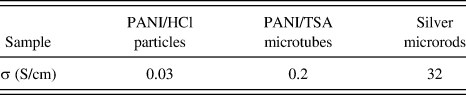
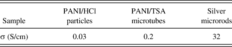
Conductivity of the PANI microtubes, PANI particles, and the silver microrods was also compared, as shown in Table I. It shows that the conductivity of PANI microtubes and PANI particles is 0.2 and 0.03 S/cm, respectively. The different result is attributed to various morphology and doped agent, which is consistent with the result of previous works.Reference Sun, Guo, Yang, Zhou, Cui, Liu and Zhao3, Reference Raghava Reddy, Pill Lee and Iyengar Gopalan21 Furthermore, the high conductivity (approximately 32.0 S/cm) of silver microrods is observed in Table I. The electrical conductivity (32.0 S/cm) is lower than that of the silver bulk (106 S/cm).Reference Aziz, Abidin and Arof22 The result is attributed to that the surface of silver microrods was coated with PANI.
The conductivity of synthesized PANI and its composites.
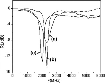
Reflection losses (RL) of the PANI microtubes, PANI particles, and silver microrods were further compared, as shown in Fig. 8. It can be seen that the microwave absorption of gum vulcanizate is about −15.5 dB for PANI microtubes, which is higher than that of PANI microrods reported in a previous work.Reference Sun, Guo, Yang, Zhou, Cui, Liu and Zhao3 Present PANI/HCl particles exhibit maximum RL of −8.5 dB, which is almost consistent with that of PANI/TSA particles in a previous work.Reference Sun, Guo, Yang, Zhou, Cui, Liu and Zhao3 These results indicate that the microwave absorption properties of PANI are regardless of their doped agents but strongly affected by their morphologies. In addition to this, silver microrods also show high microwave absorption properties (approximately−14.5 dB), indicating that the silver microrods coated with PANI are also applied on the microwave absorption materials.
Reflection losses of (a) PANI/HCl particles, (b) PANI/TSA microtubes, and (c) silver microrods.

IV. CONCLUSION
In summary, we have developed a new method to prepare PANI microtubes. Moreover, the silver microrods were further synthesized, in which the sliver microrods were formed inside the PANI microtubes. Furthermore, the electrical and microwave absorption properties of the silver microrods were further investigated and compared with the PANI/HCl particles and PANI/TSA microtubes. The results indicated that the silver microrods coated with PANI were good electrical and microwave absorption materials. Moreover, these results also provide a new method to synthesize silver microrods applied on electrical and optical materials.
ACKNOWLEDGMENTS
This work was supported by the National Natural Science Foundation of China (No. 50025309 and No. 90201016) and University’s Science and Technology Exploiture of Shanxi Province (20080320ZX). The authors are grateful for the financial support and express their thanks to Zhang Zhiyi for helpful discussions.