


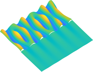

1. Introduction
The subject of wave interaction with a floating structure owing to radiation and diffraction is of considerable significance in ocean engineering for better design and safe operation, as well as environmental protection. In general, the ocean is treated as infinitely large, and the wave generated by the oscillatory motion of the structure or by its disturbance to an incident wave propagates outwards to infinity. However, there are many other cases in which the fluid region is confined or the fluid surface is not entirely free. In such a case, the wave radiated or diffracted by the body will be fully or partially reflected back to the body. This makes the interaction of a body with an external environment more complex.
A notable example of a structure in a confined water region is a channel. This problem is also related to the experimental set-up for an offshore platform in a wave tank. Early work to investigate the tank wall effect includes that by Eatock Taylor & Hung (Reference Eatock Taylor and Hung1985) on a vertical cylinder, who placed a number of cylinders at the mirror image positions formed by the two sidewalls. Yeung & Sphaier (Reference Yeung and Sphaier1989) also considered the problem of a truncated vertical circular cylinder in a channel. Their formulation used an infinite array of cylinders arranged in a plane perpendicular to the channel, and the tank wall effect, in particular its natural mode effect, was captured more accurately as a large number of cylinders could be used. A different method was used by Linton & Evans (Reference Linton and Evans1992), who constructed the velocity potential which satisfied the wall condition directly. This allowed the far-field wave in the channel away from the cylinder to be modelled accurately, and the trapped modes (Ursell Reference Ursell1951) for cylinders in a channel were captured. Wu (Reference Wu1998) considered a fully submerged sphere in an arbitrary position of the channel through the multipole expansion. It was found that in many cases the frequency corresponding to the trapped mode could be very close to the natural frequency. The sphere problem was also considered by Ursell (Reference Ursell1999), who constructed the velocity potential in an integral form. For a more realistic structure with a complicated shape, the integral equation approach based on the Green function can be used. Linton (Reference Linton1999) derived an alternative representation of the Green function for the channel, which could be calculated more efficiently. Newman (Reference Newman2016) compared three numerical approaches to include the tank wave effect, i.e. the mirror image, inclusion of the sidewall in the integral equation, and the free surface Green function satisfying the wall conditions. The results from the first two approaches became less accurate when the waves became longer, as the effects of the truncation in the mirror images or the tank wall in the integral equation became more important. Through the third method, Newman (Reference Newman2017) further provided trapped wave modes for several bodies either fixed or freely floating in the channel.
A related problem is an open water channel confined between two semi-infinite ice sheets, an example of which is that created by an icebreaker for the navigation of commercial ships (Appolonov et al. Reference Appolonov, Sazonov, Dobrodeev, Klementieva, Kudrin, Maslich, Petinov and Shaposhnikov2013). This has become an increasingly popular topic in the context of Arctic engineering. Different from the tank problem described previously, where the impermeable condition on sidewalls will force the wave to fully reflect back, the waves can pass into the region below the ice sheets. A relatively thin ice sheet can be treated as an elastic plate (Robin Reference Robin1963; Squire et al. Reference Squire, Robinson, Langhorne and Haskell1988). The plate will be set into motion, which will, in turn, create a flexural gravity wave. As the free surface wave and flexural gravity wave propagate in different media, which are reflected by their different dispersion relationships, the disturbed wave can be partially reflected back to the body. This makes the wave–body interaction more complex. Through linear velocity potential theory for fluid flow and thin elastic plate model for ice deflection, Chung & Linton (Reference Chung and Linton2005) solved the problem of incoming wave from the region below the ice sheet and then passing through the channel using a residual calculus technique. Through Wiener–Hopf and residual calculus techniques, Williams & Squire (Reference Williams and Squire2006) considered the problem of three connected ice sheets with the first and last sheets to be semi-infinite, and an open water channel could be modelled by setting the thickness of middle ice sheet zero. A free surface in confined region can also be seen through a polynya in the three-dimensional (3-D) problem. This was solved, for example, by Bennetts & Williams (Reference Bennetts and Williams2010) and the results showed that the polynya shape could have a significant effect on the diffracted wave field.
For a body inside the fluid confined by the ice sheet, Sturova (Reference Sturova2015) considered a two-dimensional (2-D) problem of wave radiation by a body submerged in the free surface channel through boundary integral equations. For a body floating on the channel surface, Ren, Wu & Thomas (Reference Ren, Wu and Thomas2016) obtained the solution for a rectangle through the matched eigenfunction expansions. Li, Shi & Wu (Reference Li, Shi and Wu2018a) developed a hybrid numerical scheme for an arbitrary shaped body, which combined eigenfunction expansions under ice sheets and boundary integral equation in the channel. Based on the solution for a body in open water and that for an ice channel without a body, Li, Shi & Wu (Reference Li, Shi and Wu2017) provided a solution for a body in a wide channel, and explicit equations for the hydrodynamic forces and motion responses were obtained. Although the solution was based on wide-spacing approximations, the results were in very good agreement with those without the approximation. Through these explicit equations, the mechanism for oscillatory behaviours of the results were uncovered.
For the 3-D problems, Ren, Wu & Ji (Reference Ren, Wu and Ji2018) considered a vertical circular cylinder in a polynya with circular shape through the series expansion. For a general 3-D problem with a practical structure and arbitrary polynya edge shape, its solution through conventional numerical methods becomes a major challenge. One of the reasons is that the commonly used Green function in ocean engineering, which allows the discretization of the structure surface only, is very difficult to construct. Another reason is the fifth derivative on the ice sheet is not easy to compute numerically. Therefore, Li, Shi & Wu (Reference Li, Shi and Wu2020a) developed a hybrid method for this problem, in which a series of integral equations under the ice sheet were constructed and coupled with the inner boundary integral equation through an orthogonal inner product. The solution procedure is highly efficient if the polynya is finite, and is effective even when there is more than one polynya or more than one structure. However, the method is less effective for an infinitely long channel. In addition, apart from a different methodology is required, there are some different physics features of the waves in the channel and their effect on the body motions need to be better understood. In particular, it has been observed by Porter (Reference Porter2018) that there could be waves trapped in the channel, which do not propagate into infinity beneath the ice sheet. The implication of this is that owing to a structure the wave may continuously propagate along the channel and affect other structures at relatively large distance away.
In this work, we develop a method that is effective for this type of channel problem. Through detailed analysis and numerical results, we acquire some in-depth understanding of the wave–body interaction in a channel confined between ice sheets. The differential equation (2.2) is first converted into an integral equation through the Green function. This may seem to be conventional for the velocity potential that satisfies the Laplace equation. However, in general, the integral equation involves the full boundary of the fluid domain, which in this case is infinite. Thus, in the free surface problem, the Green function which satisfies the boundary condition on all other surfaces apart from that on the body surface is usually derived first (Wehausen & Laitone Reference Wehausen and Laitone1960). As a result, it can then be shown that other boundaries in the integral equation can be removed apart from the body surface. The same principle may be used here. However, the derivation is not trivial and is far more complicated than the free surface problem. The Green function is obtained through taking the Fourier transform in the direction along the channel, and matched eigenfunction expansions are applied in the transverse plane. Through the Green function, those waves which may be trapped in the channel are identified and captured. With this derived Green function, it is then further shown that as in the free surface problem the other boundaries in the integral equation can indeed be removed, only the body surface needs to be retained. Numerical discretization is then applied, through which the solution are obtained. From the solution, the complex wave–channel–body interaction is investigated, together with the body–body interaction.
The paper is organized as follows. The mathematical model is formulated in § 2, and the governing equation for ice deflection together with the free ice edge conditions are described. In § 3.1 the velocity potential due to an oscillating source or the Green function is derived, based on which the boundary integral equation for the disturbed velocity potentials is constructed in § 3.2, and the formula for the hydrodynamic forces are also provided. Results are presented and discussed in § 4, followed by the conclusion in § 5. In Appendix A, the special case for ice sheet with a zero thickness is given, whereas in Appendix B the boundary integral equation for the disturbed velocity potential is derived.
2. Mathematical model
The interaction of waves with an arbitrarily shaped body floating in an open water channel is sketched in figure 1. To describe the problem, a Cartesian coordinate system  $O$–
 $xyz$ is defined, with the
 $O$–
 $xy$ plane being the undisturbed mean free water surface and the
 $z$-axis pointing vertically upwards. The channel is confined by two semi-infinite ice sheets bounded by
 $y=\pm b$, respectively. Following Squire (Reference Squire2011) and others, the ice sheet is modelled as a thin elastic plate with the associated properties, Young's modulus
 $E$, Poisson's ratio
 $\nu$, density
 $\rho _i$ and thickness
 $h$, being assumed to be constant and its draught effect being ignored. The motion of the body is assumed to be excited by an incident wave, which propagates from infinity from an angle
 $\beta$ with the positive
 $x$-axis.
Coordinate system and sketch of the problem.

The fluid with density  $\rho _w$ and constant depth
 $H$ is assumed to be inviscid, incompressible and homogeneous, and its motion to be irrotational. Thus, the velocity potential
 $\varPhi$ can be introduced to describe the fluid flow. When the amplitudes of wave motion and body motion are small compared with the wavelength and the dimension of the body, the linearized velocity potential theory can be further used. For sinusoidal motion in time with radian frequency
 $\omega$, the total velocity potential can be written as
 \begin{equation} \varPhi(x,y,z,t)=\textrm{Re}\left[ \eta_0 \phi_0(x,y,z) \,\mathrm{e}^{\mathrm{i} \omega t} + \sum_{j=1}^{6} \,\mathrm{i}\omega \eta_j \phi_j(x,y,z)\,\mathrm{e}^{\mathrm{i} \omega t} \right], \end{equation}
where  $\phi _0 = \phi _I + \phi _D$ is the scattering potential with
 $\phi _I$ and
 $\phi _D$ as the incident and diffracted potentials, respectively,
 $\eta _0$ is the amplitude of the incident wave and
 $\phi _j$ is the radiation potential owing to the jth mode of body motion in six degrees of freedom with complex amplitude
 $\eta _j$. Here,
 $\eta _j$
 $(\,j=1,2,3)$ are for the translational modes along
 $x$,
 $y$ and
 $z$ directions, respectively, whereas
 $\eta _j$
 $(\,j=4,5,6)$ are for the corresponding rotational modes. The conservation of mass requires that the velocity potential
 $\phi _j$
 $(\,j=0,\ldots ,6)$ should satisfy the Laplace equation throughout the fluid, or
 \begin{equation} \nabla^2\phi_j + \frac{\partial ^2 \phi_j}{\partial z^2} = 0, \end{equation}
where
 \begin{equation} \nabla^2 = \frac{\partial^2}{\partial x^2} + \frac{\partial^2}{\partial y^2}, \end{equation}
is the Laplacian in the horizontal plane. In the water channel, the combination of linearized dynamic and kinematic free surface boundary conditions provides
 \begin{equation} -\omega^2\phi_j + g \frac{\partial \phi_j}{\partial z} = 0 \quad (|y| \leqslant b - 0\ \text{and} \ z=0), \end{equation}
where  $g$ is the acceleration due to gravity. It is assumed that there is no gap between ice sheet and water surface. This gives
 \begin{equation} \frac{\partial W}{\partial t} = \frac{\partial \varPhi}{\partial z} \quad (|y| \geqslant b + 0 \ \text{and} \ z=0), \end{equation}
where  $W$ is the deflection of the ice sheet. Similar to (2.1), we may write
 $W$ as
 \begin{equation} W(x,y,t)=\textrm{Re}\left[ \eta_0 w_0(x,y) \,\mathrm{e}^{\mathrm{i} \omega t} + \sum_{j=1}^{6} \,\mathrm{i}\omega \eta_j w_j(x,y)\,\mathrm{e}^{\mathrm{i} \omega t} \right], \end{equation}
with
 \begin{equation} w_j = \frac{1}{\mathrm{i}\omega} \left. \frac{\partial \phi_j}{\partial z} \right|_{z=0}. \end{equation}
This, combined with the dynamic condition on the interface, gives
 \begin{equation} \left( L \nabla^4 + \rho_w g - m_i \omega^2 \right) \frac{\partial \phi_j}{\partial z} - \rho_w \omega^2 \phi_j = 0 \quad (|y| \geqslant b + 0 \ \text{and} \ z=0), \end{equation}
where  $L=Eh^3/[ 12(1 - \nu ^2) ]$ and
 $m_i = \rho _i h$ are the effective flexural rigidity and mass per unit area of the ice sheet, respectively. Here, it should be noted that in (2.4) and (2.8),
 $b-0$ and
 $b+0$ indicate that the ice edge is approached from the channel side and ice sheet side, respectively. Zero bending moment and shear force conditions are imposed at the ice edge, or (Timoshenko & Woinowsky Reference Timoshenko and Woinowsky1959)
 \begin{equation} \mathcal{B}\left( \frac{\partial \phi_j}{\partial z} \right) = 0 \quad \text{and} \quad \mathcal{S}\left( \frac{\partial \phi_j}{\partial z} \right) = 0 \quad (|y|=b+0 \ \text{and} \ z=0), \end{equation}
for  $j=0,\ldots ,6$, where the operators
 $\mathcal {B}$ and
 $\mathcal {S}$ are respectively defined as
 \begin{gather} \mathcal{B} = \frac{\partial^2}{\partial y^2} + \nu \frac{\partial^2}{\partial x^2}, \end{gather}
 \begin{gather}\mathcal{S}=\frac{\partial}{\partial y}\left[ \frac{\partial^2}{\partial y^2} + (2-\nu)\frac{\partial^2}{\partial x^2} \right]. \end{gather}
The impermeable condition on the mean wetted body surface  $S_B$ can be written as
 \begin{equation} \frac{\partial \phi_j}{\partial n} = n_j \quad \text{and} \quad \frac{\partial \phi_D}{\partial n} ={-}\frac{\partial \phi_I}{\partial n} \quad (\,j=1,\ldots,6), \end{equation}
where  $(n_1,n_2,n_3)=\boldsymbol {n}$ are the components related to the translational modes, with
 $\boldsymbol {n}$ as the unit normal vector pointing into the body,
 $(n_4,n_5,n_6)=(\boldsymbol {r}-\boldsymbol {r}_0)\times \boldsymbol {n}$ are those related to the rotational modes with
 $\boldsymbol {r}$ being the position vector measured from the origin and
 $\boldsymbol {r}_0$ being the vector to the rotational centre
 $(x_0,y_0,z_0)$. On the flat seabed, we have
 \begin{equation} \frac{\partial \phi_j}{\partial z} = 0 \quad (z={-}H), \end{equation}
for  $j=0,\ldots ,6$. At infinity, the radiation condition requires that the radiated and diffracted waves should propagate outwards.
3. Solution procedure
3.1. Green function for an open water channel confined by two semi-infinite ice sheets
To solve the boundary value problem for the disturbed velocity potential, we may first seek the corresponding Green function  $G(p,q)$ which is defined as the velocity potential at field point
 $p(x,y,z)$ owing to a source at point
 $q(\xi ,\eta ,\zeta )$. Here,
 $G$ should satisfy the following governing equation
 \begin{equation} \nabla^2G + \frac{\partial^2 G}{\partial z^2} ={-}4{\rm \pi} \delta(x-\xi)\delta(y-\eta)\delta(z-\zeta), \end{equation}
throughout the fluid, and the same boundary conditions in (2.4), (2.8), (2.9), (2.13) and the radiation condition. Here,  $\delta (x)$ is the Dirac delta function.
To derive  $G$, we use the Fourier transform
 \begin{equation} \tilde{G} = \frac{1}{2{\rm \pi}} \int_{-\infty}^{+\infty} G \,\mathrm{e}^{-\mathrm{i}\alpha x} \, \mathrm{d} x. \end{equation}
It should be mentioned that  $G$ is an oscillatory function as
 $|x| \to +\infty$. One way to perform Fourier transform for this kind of function is to introduce a small negative imaginary part in the radian frequency
 $\omega$ (Lighthill Reference Lighthill1978). In the inverse Fourier transform, the imaginary part will tend to zero. The integration path at the singularities are deflected and the radiation condition is then satisfied automatically. This procedure is used by Li, Wu & Ji (Reference Li, Wu and Ji2018b). Alternatively, we do not introduce the imaginary part in
 $\omega$. Once
 $\tilde {G}$ is derived and its inverse transform is performed, the integration path at the singularities will be decided by the radiation condition, as can be seen later. The governing equation (3.1) for
 $G$ then becomes, after Fourier transform,
 \begin{equation} -\alpha^2\tilde{G} + \frac{\partial^2 \tilde{G}}{\partial y^2} + \frac{\partial^2 \tilde{G}}{\partial z^2} ={-}2\mathrm{e}^{-\mathrm{i}\alpha\xi} \delta(y-\eta)\delta(z-\zeta). \end{equation}
Similar to (3.3), Fourier transform is applied to the boundary conditions in (2.4), (2.8) and (2.13), which provides
 \begin{gather} -\omega^2\tilde{G}+g\frac{\partial \tilde{G}}{\partial z} = 0 \quad (|y|\leqslant b-0 \ \text{and} \ z=0), \end{gather}
 \begin{gather}\left[ L\left( \alpha^2 - \frac{\partial^2}{\partial y^2} \right)^2 + \rho_w g - m_i\omega^2 \right]\frac{\partial \tilde{G}}{\partial z} - \rho_w \omega^2 \tilde{G} = 0 \quad (|y|\geqslant b+0 \ \text{and} \ z=0), \end{gather}
and
 \begin{equation} \frac{\partial \tilde{G}}{\partial z} = 0 \quad (z={-}H). \end{equation}
In the channel with  $|y|\leqslant b-0$, we may write
 $\tilde {G}$ in the vertical direction into the eigenfunction expansion as
 \begin{equation} \tilde{G}\equiv\tilde{G}_f = \sum_{m=0}^{\infty} \,\mathrm{e}^{-\mathrm{i}\alpha\xi}f_m(y)Z_m(z), \end{equation}
where the subscript  $f$ implies that the field point is in the water channel, and
 \begin{equation} Z_m(z) = \frac{\cosh[k_m(z+H)]}{\cosh(k_mH)}, \end{equation}
with  $k_m$ as the roots of the dispersion equation for a free surface, or
 \begin{equation} K_1(\omega,k) \equiv gk\tanh(kH)-\omega^2=0, \end{equation}
Here,  $k_0$ is the purely positive real root and
 $k_m$
 $(m=1,\ldots ,\infty )$ are an infinite number of purely negative imaginary roots. It should be noted that the eigenfunction expansion of
 $\tilde {G}$ in (3.7) has already satisfied the boundary conditions in (3.4) and (3.6). Without loss of generality, we may assume that the source is in the channel or
 $|\eta | < b$. Substituting (3.7) into (3.3), we have
 \begin{equation} \sum_{m=0}^{\infty} Z_m(z) [f_m''(y) + \beta_m^2 \,f_m(y)] ={-}2\delta(y-\eta)\delta(z-\zeta), \end{equation}
where  $\beta _m^2=k_m^2-\alpha ^2$, and the prime denotes derivative with respect to
 $y$. Using the orthogonality of the vertical mode
 $Z_m(z)$, we obtain
 \begin{equation} f_m''(y) + \beta_m^2 \,f_m(y) ={-}\frac{2}{P_m} \delta(y-\eta) Z_m(\zeta), \end{equation}
where
 \begin{equation} \int_{{-}H}^{0} Z_m(z)Z_m(z) \, \mathrm{d}z = P_m, \end{equation}
with
 \begin{equation} P_m = \frac{2k_mH + \sinh(2k_mH)}{4k_m\cosh^2(k_mH)}. \end{equation}
A particular solution of (3.11) can be written as
 \begin{equation} f_m(y) = \frac{1}{\mathrm{i}\beta_mP_m} \exp({-\mathrm{i}\beta_m|y-\eta|})Z_m(\zeta). \end{equation}
Here, we have assumed  $\textrm {Im}(\beta _m) \leqslant 0$ when it is a complex number and
 $\beta _m>0$ when it is a purely real number. Substituting (3.14) into (3.7), we can write the general solution as
 \begin{equation} \tilde{G}_f = \tilde{F} + \sum_{m=0}^{\infty} (a_m \varPsi_m^a + b_m \varPsi_m^b), \end{equation}
for  $|y| \leqslant b-0$, where
 \begin{equation} \tilde{F} = \sum_{m=0}^{\infty} \frac{1}{\mathrm{i}\beta_mP_m} \exp({-\mathrm{i}\alpha\xi}) \exp({-\mathrm{i}\beta_m|y-\eta|}) Z_m(\zeta)Z_m(z), \end{equation}
and
 \begin{gather} \varPsi_m^a = \exp({-\mathrm{i}\alpha\xi})\exp({-\mathrm{i}\beta_m(b-y)})Z_m(z), \end{gather}
 \begin{gather}\varPsi_m^b = \exp({-\mathrm{i}\alpha\xi})\exp({-\mathrm{i}\beta_m(b+y)})Z_m(z). \end{gather}
The summation in (3.15) is the general solution of (3.3) when its right-hand side is zero. As shown in Appendix A, the first term on the right-hand side of (3.15) is in fact the Fourier transform of the Green function for full free surface without an ice sheet, which is the same as that in Wehausen & Laitone (Reference Wehausen and Laitone1960).
In the ice covered waters, because  $y \ne \eta$, equation (3.3) can be further written as
 \begin{equation} -\alpha^2\tilde{G} + \frac{\partial^2 \tilde{G}}{\partial y^2} + \frac{\partial^2 \tilde{G}}{\partial z^2} = 0. \end{equation}
Then by following the procedure in Li, Wu & Ren (Reference Li, Wu and Ren2020b), we have
 \begin{equation} \tilde{G}\equiv\tilde{G}_\pm{=} \sum_{m={-}2}^{\infty} c_m^\pm \varPsi_m^\pm, \end{equation}
where the subscript  $+$ and
 $-$ in
 $\tilde {G}$ are for
 $y \geqslant b+0$ and
 $y \leqslant -b-0$, respectively,
 \begin{equation} \varPsi_m^\pm{=} \exp({-\mathrm{i}\alpha\xi}) \exp({\mp\mathrm{i}\gamma_m(y\mp b)})Q_m(z), \end{equation}
and
 \begin{equation} Q_m(z) = \frac{\cosh[\kappa_m(z+H)]}{\cosh(\kappa_m H)}, \end{equation}
with  $\kappa _m$ being the roots of the dispersion equation for ice sheet or
 \begin{equation} K_2(\omega,k) \equiv (Lk^4 + \rho_w g - m_i\omega^2)k\tanh(kH)-\rho_w\omega^2 = 0. \end{equation}
Here,  $\kappa _{-1}$ and
 $\kappa _{-2}$ are two complex roots with negative imaginary parts and symmetric about the imaginary axis,
 $\kappa _0$ is the purely positive real root and
 $\kappa _m$
 $(m=1,\ldots ,\infty )$ are an infinite number of purely negative imaginary roots. In (3.21),
 $\gamma _m^2 = \kappa _m^2 - \alpha ^2$ and
 ${\textrm {Im}(\gamma _m) \leqslant 0}$ when it is a complex number and
 $\gamma _m>0$ when it is a purely real number, which is based on the requirement of the radiation condition. It should be noted that
 $\tilde {G}$ in (3.20) has already satisfied the boundary conditions in (3.5) and (3.6).
There are four sets of unknown coefficients in (3.15) and (3.20), i.e.  $a_m$,
 $b_m$,
 $c_m^+$ and
 $c_m^-$. These can be determined through the continuous conditions at the interfaces
 $y = \pm b$ or
 \begin{equation} \left. \tilde{G}_\pm \right|_{y={\pm} b} = \left. \tilde{G}_f \right|_{y={\pm} b}, \end{equation}
and
 \begin{equation} \left. \frac{\partial \tilde{G}_\pm}{\partial y} \right|_{y={\pm} b} = \left. \frac{\partial \tilde{G}_f}{\partial y} \right|_{y={\pm} b}, \end{equation}
together with the ice edge conditions. We may apply the Fourier transform (3.2) to the free ice edge conditions (2.9), which provides
 \begin{equation} \tilde{\mathcal{B}} \left( \frac{\partial \tilde{G}}{\partial z} \right) = 0 \quad \text{and} \quad \tilde{\mathcal{S}} \left( \frac{\partial \tilde{G}}{\partial z} \right) = 0, \end{equation}
with
 \begin{gather} \tilde{\mathcal{B}} = \frac{\partial^2}{\partial y^2} - \nu \alpha^2, \end{gather}
 \begin{gather}\tilde{\mathcal{S}} = \frac{\partial}{\partial y} \left[ \frac{\partial^2}{\partial y^2} - (2-\nu)\alpha^2 \right]. \end{gather}
To impose these conditions, we may adopt Green's second theorem over the boundary  $\varGamma _+$ of the domain with
 $y\geqslant b+0$, which provides
 \begin{equation} \oint_{\varGamma_+} \left( \tilde{G}_+ \frac{\partial \varPsi_m^+}{\partial n} - \frac{\partial \tilde{G}_+}{\partial n} \varPsi_m^+ \right) \mathrm{d}l = 0. \end{equation}
Here, it should be noted that  $\tilde {G}_+$ and
 $\varPsi _m^+$ should satisfy the same boundary conditions on the flat seabed, ice sheet and the vertical surface at the far field
 $y=+\infty$. Removing the zero terms, we have
 \begin{equation} -\int_{{-}H}^{0} \left( \tilde{G}_+ \frac{\partial \varPsi_m^+}{\partial y} - \frac{\partial \tilde{G}_+}{\partial y} \varPsi_m^+ \right)_{y={+}b} \, \mathrm{d}z + \int_{{+}b}^{+\infty} \left( \tilde{G}_+ \frac{\partial \varPsi_m^+}{\partial z} - \frac{\partial \tilde{G}_+}{\partial z} \varPsi_m^+ \right)_{z=0} \, \mathrm{d} y =0. \end{equation}
Equation (3.5) provides
 \begin{equation} \tilde{G}_+{=} \frac{L}{\rho_w \omega^2}\left( \alpha^4 - 2\alpha^2\frac{\partial^2}{\partial y^2} + \frac{\partial ^4}{\partial y^4} \right)\frac{\partial \tilde{G}_+}{\partial z} +\frac{\rho_w g - m_i\omega^2}{\rho_w \omega^2}\frac{\partial \tilde{G}_+}{\partial z}, \end{equation}
which is also satisfied by  $\psi _m^+$. Substituting (3.31) into (3.30), and using integration by parts over the ice sheet surface, we can obtain
 \begin{align} & \int_{{-}H}^{0} \left( \tilde{G}_+ \frac{\partial \varPsi_m^+}{\partial y} - \frac{\partial \tilde{G}_+}{\partial y} \varPsi_m^+ \right)_{y={+}b} \, \mathrm{d}z + \frac{L}{\rho_w\omega^2} \left[ 2\alpha^2\left( \frac{\partial \tilde{G}_+}{\partial z}\frac{\partial^2 \varPsi_m^+}{\partial y \partial z} - \frac{\partial^2 \tilde{G}_+}{\partial y \partial z}\frac{\partial \varPsi_m^+}{\partial z} \right) \right. \nonumber\\ &\quad \left. + \left( \frac{\partial^4 \tilde{G}_+}{\partial y^3 \partial z}\frac{\partial \varPsi_m^+}{\partial z} - \frac{\partial \tilde{G}_+}{\partial z}\frac{\partial^4 \varPsi_m^+}{\partial y^3\partial z} \right) - \left( \frac{\partial^3 \tilde{G}_+}{\partial y^2 \partial z}\frac{\partial^2 \varPsi_m^+}{\partial y \partial z} - \frac{\partial^2 \tilde{G}_+}{\partial y \partial z}\frac{\partial^3 \varPsi_m^+}{\partial y^2\partial z} \right) \right]_{y={+}b,z=0} =0. \end{align}
Similarly, we have at  $y=-b$
 \begin{align} & \int_{{-}H}^{0} \left( \tilde{G}_- \frac{\partial \varPsi_m^-}{\partial y} - \frac{\partial \tilde{G}_-}{\partial y} \varPsi_m^- \right)_{y={-}b} \, \mathrm{d}z + \frac{L}{\rho_w\omega^2} \left[ 2\alpha^2\left( \frac{\partial \tilde{G}_-}{\partial z}\frac{\partial^2 \varPsi_m^-}{\partial y \partial z} - \frac{\partial^2 \tilde{G}_-}{\partial y \partial z}\frac{\partial \varPsi_m^-}{\partial z} \right) \right. \nonumber\\ &\quad\left. + \left( \frac{\partial^4 \tilde{G}_-}{\partial y^3 \partial z}\frac{\partial \varPsi_m^-}{\partial z} - \frac{\partial \tilde{G}_-}{\partial z}\frac{\partial^4 \varPsi_m^-}{\partial y^3\partial z} \right) - \left( \frac{\partial^3 \tilde{G}_-}{\partial y^2 \partial z}\frac{\partial^2 \varPsi_m^-}{\partial y \partial z} - \frac{\partial^2 \tilde{G}_-}{\partial y \partial z}\frac{\partial^3 \varPsi_m^-}{\partial y^2\partial z} \right) \right]_{y={-}b,z=0} =0. \end{align}
Invoking the free ice edge condition (3.26a,b), we have
 \begin{equation} \frac{\partial^3 \tilde{G}_\pm}{\partial y^2 \partial z} = \nu \alpha^2 \frac{\partial \tilde{G}_\pm}{\partial z} \quad \text{and} \quad \frac{\partial^4 \tilde{G}_\pm}{\partial y^3 \partial z} = (2-\nu) \alpha^2 \frac{\partial^2\tilde{G}_\pm}{\partial y \partial z} \end{equation}
at  $y = \pm b$ and
 $z = 0$. Substituting this equation into (3.32) and (3.33), we obtain
 \begin{align} & \int_{{-}H}^{0} \left( \tilde{G}_f \frac{\partial \varPsi_m^\pm}{\partial y} - \frac{\partial \tilde{G}_\pm}{\partial y} \varPsi_m^\pm \right)_{y={\pm} b} \, \mathrm{d}z + \frac{L}{\rho_w\omega^2} \left\{ \alpha^2\left[ (2-\nu)\frac{\partial \tilde{G}_\pm}{\partial z}\frac{\partial^2 \varPsi_m^\pm}{\partial y \partial z}\right. \right. \nonumber\\ &\quad \left. -\nu\frac{\partial^2 \tilde{G}_\pm}{\partial y \partial z}\frac{\partial \varPsi_m^\pm}{\partial z} \right] \left. + \frac{\partial^2 \tilde{G}_\pm}{\partial y \partial z} \frac{\partial^3\varPsi_m^\pm}{\partial y^2 \partial z} - \frac{\partial \tilde{G}_\pm}{\partial z} \frac{\partial^4 \varPsi_m^\pm}{\partial y^3 \partial z} \right\}_{y={\pm} b, z=0} =0, \end{align}
where the continuity condition (3.24) has been used. It should be noted that the free ice edge condition has been imposed in (3.35) through replacing the corresponding terms on the ice edge in (3.32) and (3.33). There is no need to have further actions to impose this condition. The way to satisfy the ice edge condition here is similar to that of Ren et al. (Reference Ren, Wu and Thomas2016). To impose the continuity condition (3.25), we multiply both sides of (3.15) with  $Z_m(z)$ and then integrate with respect to
 $z$. This gives
 \begin{align} \int_{{-}H}^{0} \frac{\partial \tilde{G}_+}{\partial y} Z_m(z) \, \mathrm{d}z &= \int_{{-}H}^{0} \frac{\partial \tilde{G}_f}{\partial y} Z_m(z) \, \mathrm{d}z \nonumber\\ &= \mathrm{i}\beta_m P_m (a_m - b_m \exp({-2\mathrm{i}\beta_m b})) \nonumber\\ &\quad - \exp({-\mathrm{i}\alpha \xi}) \exp({-\mathrm{i}\beta_m(b-\eta)}) Z_m(\zeta), \end{align}
 \begin{align} \int_{{-}H}^{0} \frac{\partial \tilde{G}_-}{\partial y} Z_m(z) \, \mathrm{d}z &= \int_{{-}H}^{0} \frac{\partial \tilde{G}_f}{\partial y} Z_m(z) \, \mathrm{d}z \nonumber\\ &= \mathrm{i}\beta_m P_m (a_m \exp({-2\mathrm{i}\beta_m b}) - b_m) \nonumber\\ &\quad + \exp({-\mathrm{i}\alpha \xi})\exp({-\mathrm{i}\beta_m(b+\eta)}) Z_m(\zeta), \end{align}
for  $y=+b$ and
 $y=-b$, respectively, in which (3.12) has been used. Substituting (3.15) and (3.20) into (3.35) and (3.36), we have at
 $y=+b$
 \begin{align} & \gamma_m \sum_{\tilde{m}=0}^{\infty} (a_{\tilde{m}} + b_{\tilde{m}} \exp({-2\mathrm{i}\beta_{\tilde{m}}b})) V_{m,{\tilde{m}}} - c_m^+ \gamma_m U_m -\frac{LT_m}{\rho_w \omega^2} \sum_{\tilde{m}={-}2}^{\infty} c_{\tilde{m}}^+ T_{\tilde{m}} [\nu\alpha^2(\gamma_{\tilde{m}}+\gamma_m) \nonumber\\ &\qquad - 2\alpha^2\gamma_m + \gamma_m^2(\gamma_{\tilde{m}}-\gamma_m) - \gamma_{\tilde{m}} (\kappa_m^2 + \kappa_{\tilde{m}}^2)]\nonumber\\ &\quad =\mathrm{i}\gamma_m\sum_{\tilde{m}=0}^{\infty}\frac{1}{\beta_{\tilde{m}}P_{\tilde{m}}} \exp({-\mathrm{i}\beta_{\tilde{m}}(b-\eta)})Z_{\tilde{m}}(\zeta)V_{m,{\tilde{m}}}, \end{align}
 \begin{align} &\beta_m P_m ( b_m \exp({-2\mathrm{i}\beta_m b}) - a_m ) - \sum_{\tilde{m}={-}2}^{\infty} c_{\tilde{m}}^+ \gamma_{\tilde{m}}V_{{\tilde{m}},m} = \mathrm{i} \exp({-\mathrm{i}\beta_m(b-\eta)})Z_m(\zeta), \end{align}
where
 \begin{gather} T_m = \kappa_m \tanh(\kappa_m H), \end{gather}
 \begin{gather}U_m = \frac{2\kappa_m H + \sinh(2\kappa_m H)}{4\kappa_m\cosh^2(\kappa_m H)} + \frac{2LT_m^2\kappa_m^2}{\rho_w\omega^2}, \end{gather}
 \begin{gather}V_{m,{\tilde{m}}}=\int_{{-}H}^{0} Q_m Z_{\tilde{m}} \, \mathrm{d}z = \frac{T_m - k_{\tilde{m}}\tanh(k_{{\tilde{m}}H})}{\kappa_m^2 - k_{\tilde{m}}^2}. \end{gather}
It should be noted that in (3.38) the following relationship has been used
 \begin{equation} \int_{{-}H}^{0} Q_m Q_{\tilde{m}} \, \mathrm{d}z = \delta_{m,\tilde{m}}U_m - \frac{LT_mT_{\tilde{m}}}{\rho_w\omega^2} (\kappa_m^2 + \kappa_{\tilde{m}}^2), \end{equation}
where  $\delta _{m,\tilde {m}}$ is the Kronecker delta function. Similarly, we have at
 $y=-b$
 \begin{align} & \gamma_m \sum_{\tilde{m}=0}^{\infty} (a_{\tilde{m}} \exp({-2\mathrm{i}\beta_{\tilde{m}}b}) + b_{\tilde{m}} ) V_{m,{\tilde{m}}} - c_m^- \gamma_m U_m -\frac{LT_m}{\rho_w \omega^2} \sum_{\tilde{m}={-}2}^{\infty} c_{\tilde{m}}^- T_{\tilde{m}} [\nu\alpha^2(\gamma_{\tilde{m}}+\gamma_m) \nonumber\\ &\qquad - 2\alpha^2\gamma_m + \gamma_m^2(\gamma_{\tilde{m}}-\gamma_m) - \gamma_{\tilde{m}} (\kappa_m^2 + \kappa_{\tilde{m}}^2)]\nonumber\\ &\quad =\mathrm{i}\gamma_m\sum_{\tilde{m}=0}^{\infty}\frac{1}{\beta_{\tilde{m}}P_{\tilde{m}}} \exp({-\mathrm{i}\beta_{\tilde{m}}(b+\eta)})Z_{\tilde{m}}(\zeta)V_{m,{\tilde{m}}}, \end{align}
 \begin{align} &\beta_m P_m ( a_m \exp({-2\mathrm{i}\beta_m b}) - b_m ) - \sum_{\tilde{m}={-}2}^{\infty} c_{\tilde{m}}^- \gamma_{\tilde{m}}V_{{\tilde{m}},m} = \mathrm{i} \exp({-\mathrm{i}\beta_m(b+\eta)})Z_m(\zeta). \end{align}
From (3.39) and (3.45), we can obtain
 \begin{align} a_m &= \frac{1}{\beta_mP_m(\exp({-4\mathrm{i}\beta_m b}) - 1)} \sum_{\tilde{m}={-}2}^{\infty} ( c_{\tilde{m}}^+{+} c_{\tilde{m}}^- \exp({-2\mathrm{i}\beta_m b})) \gamma_{\tilde{m}} V_{\tilde{m},m} \nonumber\\ &\quad + \mathrm{i}Z_m(\zeta) \frac{\exp({-\mathrm{i}\beta_m (3b+\eta)}) + \exp({-\mathrm{i}\beta_m (b-\eta)})}{\beta_mP_m(\exp({-4\mathrm{i}\beta_m b}) - 1)}, \end{align}
 \begin{align} b_m &= \frac{1}{\beta_mP_m(\exp({-4\mathrm{i}\beta_m b}) - 1)} \sum_{\tilde{m}={-}2}^{\infty} ( c_{\tilde{m}}^+ \exp({-2\mathrm{i}\beta_m b}) + c_{\tilde{m}}^-) \gamma_{\tilde{m}} V_{\tilde{m},m} \nonumber\\ &\quad + \mathrm{i}Z_m(\zeta) \frac{\exp({-\mathrm{i}\beta_m (b+\eta)}) + \exp({-\mathrm{i}\beta_m (3b-\eta)})}{\beta_mP_m(\exp({-4\mathrm{i}\beta_m b}) - 1)}. \end{align}
Substituting these two equations into (3.38), we have
 \begin{align} & -c_m^+ \gamma_mU_m + \gamma_m \sum_{\tilde{m}=0}^{\infty} \frac{V_{m,\tilde{m}}}{\beta_{\tilde{m}} P_{\tilde{m}}(\exp({-4\mathrm{i}\beta_{\tilde{m}}b}) - 1)}\nonumber\\ &\qquad \times \sum_{n={-}2}^{\infty} [ c_n^+ (1 + \exp({-4\mathrm{i}\beta_{\tilde{m}}b})) + 2c_n^- \exp({-2\mathrm{i}\beta_{\tilde{m}}b}) ] \gamma_n V_{n,\tilde{m}} \nonumber\\ &\qquad - \frac{LT_m}{\rho_w \omega^2} \sum_{\tilde{m}={-}2}^{\infty} c_{\tilde{m}}^+T_{\tilde{m}} [ \nu\alpha^2 (\gamma_{\tilde{m}} + \gamma_m) - 2\alpha^2\gamma_m + \gamma_m^2 (\gamma_{\tilde{m}} - \gamma_m) - \gamma_{\tilde{m}} (\kappa_m^2 + \kappa_{\tilde{m}}^2) ] \nonumber\\ &\quad ={-}2\mathrm{i}\gamma_m \sum_{\tilde{m}=0}^{\infty} \frac{\exp({-\mathrm{i} \beta_{\tilde{m}} (b-\eta)}) + \exp({-\mathrm{i}\beta_{\tilde{m}} (3b+\eta)})}{\beta_{\tilde{m}} P_{\tilde{m}}(\exp({-4\mathrm{i}\beta_{\tilde{m}} b}) - 1)} Z_{\tilde{m}}(\zeta) V_{m,\tilde{m}}. \end{align}
Similarly, we have for (3.44)
 \begin{align} & -c_m^- \gamma_mU_m + \gamma_m \sum_{\tilde{m}=0}^{\infty} \frac{V_{m,\tilde{m}}}{\beta_{\tilde{m}} P_{\tilde{m}}(\exp({-4\mathrm{i}\beta_{\tilde{m}}b}) - 1)}\nonumber\\ &\qquad \times \sum_{n={-}2}^{\infty} [ 2c_n^+ \exp({-2\mathrm{i}\beta_{\tilde{m}}b}) + c_n^- (1 + \exp({-4\mathrm{i}\beta_{\tilde{m}}b})) ] \gamma_n V_{n,\tilde{m}} \nonumber\\ &\qquad - \frac{LT_m}{\rho_w \omega^2} \sum_{\tilde{m}={-}2}^{\infty} c_{\tilde{m}}^-T_{\tilde{m}} [ \nu\alpha^2 (\gamma_{\tilde{m}} + \gamma_m) - 2\alpha^2\gamma_m + \gamma_m^2 (\gamma_{\tilde{m}} - \gamma_m) - \gamma_{\tilde{m}} (\kappa_m^2 + \kappa_{\tilde{m}}^2) ] \nonumber\\ &\quad ={-}2\mathrm{i}\gamma_m \sum_{\tilde{m}=0}^{\infty} \frac{\exp({-\mathrm{i}\beta_{\tilde{m}} (b+\eta)}) + \exp({-\mathrm{i}\beta_{\tilde{m}} (3b-\eta)})}{\beta_{\tilde{m}}P_{\tilde{m}}(\exp({-4\mathrm{i}\beta_{\tilde{m}} b}) - 1)} Z_{\tilde{m}}(\zeta) V_{m,\tilde{m}}. \end{align}
This shows  $c_m^+$ and
 $c_m^-$ can be solved first independently from (3.48) and (3.49), after which
 $a_m$ and
 $b_m$ can be obtained directly from (3.46) and (3.47).
In practical computations, (3.48) and (3.49) can be solved through truncating the infinite summation at a finite number  $m=M$. Here, it should be noted that the matrix coefficients for the unknowns only depend on the value of
 $\alpha$ and are independent of the source position. Therefore, the inverse does not have to be recalculated at different source position. In addition, from (3.46) and (3.47), we can see that the truncation for
 $a_m$ and
 $b_m$ can be made at a value different from
 $M$.
The Green function  $G$ can be found through applying the inverse Fourier transform to
 $\tilde {G}$, or
 \begin{equation} G = \int_{-\infty}^{+\infty} \tilde{G} \,\mathrm{e}^{+\mathrm{i}\alpha x} \, \mathrm{d} \alpha. \end{equation}
Substituting (3.15) and (3.20) into this equation, and using the symmetry property of  $\tilde {G}$, we have
 \begin{align} G = \left\{\begin{array}{ll} \displaystyle 2\sum_{m={-}2}^{\infty} Q_m(z) \int_{0}^{+\infty} c_m^+ \exp({-\mathrm{i}\gamma_m(y-b)}) \cos[\alpha(x-\xi)] \, \mathrm{d}\alpha, & y\geqslant b+0 \\ \displaystyle F+2\sum_{m=0}^{\infty} Z_m(z) \int_{0}^{+\infty} (a_m \exp({-\mathrm{i}\beta_m(b-y)} ) & \\ \quad + b_m \, \exp({-\mathrm{i}\beta_m(b+y)})) \cos[\alpha(x-\xi)] \, \mathrm{d}\alpha, & |y| \leqslant b-0 \\ \displaystyle 2\sum_{m={-}2}^{\infty} Q_m(z) \int_{0}^{+\infty} c_m^- \exp({+\mathrm{i}\gamma_m(y+b)}) \cos[\alpha(x-\xi)] \, \mathrm{d}\alpha, & y\leqslant -b-0. \end{array} \right. \end{align}
where
 \begin{equation} F = \sum_{m=0}^{\infty} \frac{1}{\mathrm{i}P_m} Z_m(\zeta)Z_m(z)I_m, \end{equation}
with
 \begin{equation} I_m = \int_{-\infty}^{+\infty} \frac{1}{\beta_m} \exp({+\mathrm{i}\alpha(x-\xi)}) \exp({-\mathrm{i}\beta_m|y-\eta|}) \, \mathrm{d}\alpha = {\rm \pi}H_0^{(2)}(k_mR). \end{equation}
Here,  $F$ is identical to the Green function for a free surface in (A16), and (A11) and (A14) have been used in (3.53). It should be noted that when the ice thickness
 $h=0$, the Green function in (3.51) will become that for a free surface, as shown in Appendix A. As shown in Appendix B, we also have that the Green function is symmetric regarding the source and field points or
 \begin{equation} G(p,q) - G(q,p)=0. \end{equation}
When  $\alpha \to k_0$ or
 $\beta _0^2 = k_0^2 - \alpha ^2 \to 0$, (3.38) and (3.44) show that there is a singularity on the right-hand side. However, it is of square root order, or
 $1/(k_0^2 - \alpha ^2)^{1/2}$ in the inverse Fourier transform, which numerically can be computed through the Gauss–Chebyshev procedure (Abramowitz & Stegun Reference Abramowitz and Stegun1965). Special care should be paid to the integrals over the domain
 $\kappa _0 < \alpha < k_0$ when
 $k_0>\kappa _0$. In such a case, there are non-decaying wave modes at
 $x=\pm \infty$ at discrete wave numbers of
 $\kappa _0 < \alpha _1 < \ldots < \alpha _N < k_0$, which correspond to the trapped modes in Porter (Reference Porter2018). This means that there may be a number of poles at
 $\alpha _j$
 $(\,j=1,\ldots ,N)$ of the integrand in (3.51). To satisfy the radiation condition, which states that the waves should propagate away from the source, the integral route in (3.51) from
 $0$ to
 $+\infty$ should pass over these poles. Then, through applying the Fourier integrals in Wehausen & Laitone (Reference Wehausen and Laitone1960), we can obtain the asymptotic expression of (3.51) at
 $|x-\xi | \to +\infty$, or
 \begin{align} G_\infty \equiv & \lim_{|x-\xi| \to +\infty} G ={-}2\mathrm{i}{\rm \pi} \sum_{j=1}^{N} \exp({-\mathrm{i}\alpha_j |x-\xi|}) \nonumber\\ &\quad \times \left\{ \begin{array}{ll} \displaystyle\sum_{m={-}2}^{\infty} Q_m(z) \lim_{\alpha \to \alpha_j} [(\alpha - \alpha_j)c_m^+\exp({-\mathrm{i}\gamma_{m,j}(y-b)})], & y\geqslant b+0 \\ \displaystyle \sum_{m=0}^{\infty} Z_m(z) \lim_{\alpha \to \alpha_j} \{(\alpha - \alpha_j)[a_m \exp({-\mathrm{i}\beta_{m,j}(b-y)}) & \\ \quad + b_m \exp({-\mathrm{i}\beta_{m,j}(b+y)})]\}, & |y| \leqslant b-0 \\ \displaystyle \sum_{m={-}2}^{\infty} Q_m(z) \lim_{\alpha \to \alpha_j} [(\alpha - \alpha_j)c_m^- \exp({+\mathrm{i}\gamma_{m,j}(y+b)})], & y\leqslant -b-0. \end{array} \right. \end{align}
For  $|y| \leqslant b-0$, the wave component of
 $\alpha _j$ exists inside the channel. However, for
 $|y| \geqslant b + 0$ below the ice sheet,
 $\gamma _{m,j}$, corresponding to
 $\alpha _j$, always have
 $\textrm {Im}{(\gamma _{m,j})}<0$, which indicates that the wave of
 $\alpha _j$ will decay exponentially with
 $y$. It should also be noted that
 $F$ in (3.51) for
 $|y| \leqslant b-0$ corresponds to the cylindrical wave at the far field, the amplitude of which decreases with
 $1/\sqrt {R}$. Therefore, this term has been dropped in (3.55) because it will diminish as
 $|x-\xi | \to +\infty$.
To search for  $\alpha _j$ numerically, we may use the fact that the singularities of
 $a_m$,
 $b_m$,
 $c_m^+$ and
 $c_m^-$ are of the form of
 $1/(\alpha -\alpha _j)$. When (3.46)– (3.49) are solved at different
 $\alpha$, sufficiently small step
 $\Delta \alpha$ is used. When the results become very large at both
 $\alpha$ and
 $\alpha + \Delta \alpha$, and their signs are different, one of the
 $\alpha _j$ will exist within this step. The accuracy of
 $\alpha _j$ can be refined by using the further smaller steps within the region.
The calculation of the limit in (3.55) needs some special attention. In theory, the limit can be obtained through L'Hospital's rule. However, the integrand and its singularities here are not explicitly given and they are obtained from the numerical procedure described previously. Thus, the following method is used to calculate the limit. We may consider a function  $f(\alpha )$, which has a singularity in the form
 $f(\alpha ) \to g(\alpha )/(\alpha - \alpha _j)$ as
 $\alpha \to \alpha _j$. Then,
 $g(\alpha _j) = \lim _{\alpha \to \alpha _j} (\alpha - \alpha _j) f(\alpha )$ can be found numerically by
 \begin{align} g(\alpha_j) & = \frac{g(\alpha_j + \Delta\alpha) + g(\alpha_j - \Delta\alpha)}{2} + O[g''(\alpha_j)(\Delta\alpha)^2] \nonumber\\ & \approx \Delta\alpha \frac{f(\alpha_j + \Delta\alpha) - f(\alpha_j - \Delta\alpha)}{2}. \end{align}
3.2. Solution to the disturbed velocity potential for a body in the ice channel
As shown in Appendix B, we have the boundary integral equation for the disturbed velocity potential  $\phi$ as follow
 \begin{equation} \ell \phi(p) = \int_{S_B} \left[ G(p,q) \frac{\partial \phi(q)}{\partial n_q} - \frac{\partial G(p,q)}{\partial n_q} \phi(q) \right] \, \mathrm{d}s_q, \end{equation}
where only the integral over the mean wetted body surface  $S_B$ is needed, and
 $\ell$ is the solid angle at point
 $p$. As noted by Lee, Newman & Zhu (Reference Lee, Newman and Zhu1996) in the free surface problem, for floating bodies there could exist a discrete spectrum of irregular frequencies, at which the solution to the boundary integral equation is non-unique. Similar irregular frequencies also exist in (3.57). To remove the irregular frequencies, we follow the procedure described in Lee et al. (Reference Lee, Newman and Zhu1996) and rewrite (3.57) equivalently as
 \begin{equation} \ell \phi(p) + \int_{S_B+S_E} \frac{\partial G(p,q)}{\partial n_q} \phi(q) \,\mathrm{d}s_q = \int_{S_B} G(p,q) \frac{\partial \phi(q)}{\partial n_q} \, \mathrm{d}s_q \quad \text{for} \ p \in S_B, \end{equation}
and
 \begin{equation} -4{\rm \pi} \phi(p) + \int_{S_B+S_E} \frac{\partial G(p,q)}{\partial n_q} \phi(q) \, \mathrm{d}s_q = \int_{S_B} G(p,q) \frac{\partial \phi(q)}{\partial n_q} \, \mathrm{d}s_q \quad \text{for} \ p \in S_E, \end{equation}
where  $S_E$ is the extended surface interior the body at
 $z=0$. This has been found to remove the irregular frequencies effectively.
For the radiation problem,  $\phi = \phi _j$ and
 $\partial \phi _j / \partial n = n_j$ can be used directly in the integral equations (3.58) and (3.59). However, for the diffraction problem, it has two components. The incident wave will be diffracted by both the channel and the body. Thus, similar to Li et al. (Reference Li, Wu and Ji2018b), we write the total diffracted potential as
 \begin{equation} \phi_D = \phi_D^1 + \phi_D^2, \end{equation}
where  $\phi _D^1$ is the diffracted potential of the flexural gravity incident potential
 $\phi _I$ by the water channel, and
 $\phi _D^2$ is that by the body to
 $\varphi = \phi _I + \phi _D^1$. It should be mentioned that
 $\varphi$ satisfies the ice edge condition (2.9). Here, the incident potential
 $\phi _I$ can be written as
 \begin{equation} \phi_I = \varphi_I(y,z) \,\mathrm{e}^{-\mathrm{i}\kappa_x x}, \end{equation}
with
 \begin{equation} \varphi_I = A \,\mathrm{e}^{-\mathrm{i}\kappa_y y} Q_0(z), \end{equation}
where  $A=\mathrm {i}\omega /[\kappa _0\tanh (\kappa _0H)]$,
 $\kappa _x = \kappa _0 \cos \beta$ and
 $\kappa _y = \kappa _0\sin \beta$. Correspondingly, the potential
 $\varphi$ can be written as
 \begin{equation} \varphi = \bar{\varphi}(y,z) \,\mathrm{e}^{-\mathrm{i}\kappa_x x}. \end{equation}
Here  $\bar {\varphi }$ or
 $\phi _D^1$ can be obtained virtually in the same way as
 $\tilde {G}$. The main difference is that
 $\alpha$ should be replaced by
 $\kappa _x$ and terms on the right-hand sides due to
 $\tilde {F}$ in (3.46)– (3.49) should be replaced by the contribution due to
 $\phi _I$. Because
 $\varphi =\phi _I + \phi _D^1$ satisfies the conditions at the ice sheet edge, then
 $\phi _D^2$ should also satisfy these conditions. Thus, we can apply the integral equation (3.57) to
 $\phi _D^2$ by imposing the boundary condition
 $\partial \phi _D^2 / \partial n = -\partial \varphi / \partial n$ on the body surface.
After the velocity potentials have been found, the pressure at any point in fluid can be computed through the linearized Bernoulli equation. Then the hydrodynamic forces on the body can be obtained through integrating the pressure over its surface. Based on the decomposition of the velocity potential in (2.1), we may divide the total hydrodynamic loads into two parts, i.e. the radiation force due to the forced oscillatory motions and the wave exciting force due to the scattering potential (Newman Reference Newman1977). For the radiation potential, we have
 \begin{equation} \mu_{jk} - \mathrm{i}\frac{\lambda_{jk}}{\omega} = \rho_w \int_{S_B} \phi_kn_j \, \mathrm{d}s, \end{equation}
where  $\mu _{jk}$ and
 $\lambda _{jk}$ are the added mass and damping coefficient, respectively. For the scattering potential, we have
 \begin{equation} f_{E,j} ={-}\mathrm{i} \omega \rho_w \int_{S_B} \phi_0 n_j \, \mathrm{d}s, \end{equation}
where  $f_{E,j}$ is the wave exciting force.
4. Numerical results
To provide meaningful results in physics, the typical values of the parameters of ice sheet and fluid are taken to be
 \begin{align} \left.\begin{gathered} E = 5 \ \mathrm{GPa}, \quad \nu = 0.3, \quad \rho_i = 922.5 \ \mathrm{kg}\ \textrm{m}^{{-}3}, \quad h = 1 \, \mathrm{m}, \quad \rho_w = 1025 \ \mathrm{kg}\ \textrm{m}^{{-}3}, \\ H = 100 \ \mathrm{m}, \end{gathered}\right\} \end{align}
which are similar to those obtained from the field experiment in polar regions (Squire et al. Reference Squire, Dugan, Wadhams, Rottier and Liu1995). The channel width is chosen as  $60\ \mathrm {m} \leqslant 2b \leqslant 100\ \mathrm {m}$, which can be developed, for example, by an icebreaker with azimuth thrusters (Riska, Lohi & Eronen Reference Riska, Lohi and Eronen2005). In the following text, all the numerical results will be provided in the dimensionless form, based on the combinations of three basic parameters, i.e. density of water
 $\rho _w$, acceleration due to gravity
 $g = 9.8\ \mathrm {m}\ \textrm {s}^{-2}$ and a characteristic length scale. For each case, the wave number
 $k_0$ for free surface wave is given, and the corresponding wave frequency
 $\omega$ can be obtained through the dispersion equation (3.9).
4.1. Wave induced by a source submerged in the ice channel
We first consider the wave induced by a source submerged in the channel confined by two semi-infinite ice sheets, with the ice sheet thickness  $h=1\ \mathrm {m}$ taken as the characteristic length scale and the half channel width fixed to be
 $b=50\ \mathrm {m}$. This is to shed some lights on some features of the free surface and the ice sheet deflection pattern. Numerical calculations are carried out through truncating the infinite summations in (3.51) to a finite number, or keeping only the first
 $M_G + 1$ terms. The wave elevation is computed based on the kinematic boundary condition, which gives
 \begin{equation} w = \frac{1}{\mathrm{i}\omega} \left. \frac{\partial G}{\partial z} \right|_{z=0}. \end{equation}
The values of  $\alpha _j$ are obtained through the procedure described towards the end of § 3.1. It should be noted that
 $\alpha _j$ do not depend on the location of the source. However, each
 $\alpha _j$ corresponds to a wave in the channel either symmetric or antisymmetric about
 $y=0$ (Porter Reference Porter2018). When the source is located at the centre of the channel, only symmetric waves will be triggered. Thus, to capture all
 $\alpha _j$, corresponding to both symmetric and antisymmetric modes, they are computed through the case with the source located at
 $(0,b/2,-H/100)$. To ensure the accuracy of
 $\alpha _j$, as well as the accuracies of integration and the approximation of (3.56), the step
 $\Delta \alpha$ is chosen from the lowest value among
 $0.0001$,
 $(\alpha _j - \alpha _{j-1})/50$ and
 $(\alpha _{j+1} - \alpha _j)/50$ when
 $\alpha$ is between
 $\alpha _{j-1}$ and
 $\alpha _{j+1}$, where
 $\alpha _0 = \kappa _0$ for
 $j=1$ and
 $\alpha _{N+1}=k_0$ for
 $j=N$ with
 $N$ as the number of the singularities. Searching for
 $\alpha _j$ is done numerically through the Gauss elimination with partial pivoting for the matrix equation. When the solution of the unknown in the last line jumps from a large positive (negative) number
 $\mathcal {R}$ to a large negative (position) number
 $-\mathcal {R}$ within a small
 $\Delta \alpha$, it is assumed that
 $\alpha _j$ is within
 $\Delta \alpha$. Here we have used
 $\mathcal {R}=10^{10}$ and
 $\Delta \alpha = 10^{-16}$. Figure 2 provides the first symmetric trapped mode
 $\alpha$ at a large water depth
 $H/h=100$ against
 $K=\omega ^2/g$. The infinite summations are truncated at
 $M_G=100$. As a comparison, the result in Porter (Reference Porter2018) for infinite water depth is also provided, and the same parameters of ice sheet and fluid as well as the characteristic length scale are taken. It can be observed from this figure that the values of
 $\alpha$ for
 $H/h=100$ are close to the values in Porter (Reference Porter2018) for infinite water depth. It should be noted that in the present formulation, the expansion in the vertical direction is, in fact, a cosine series. When
 $H$ is very large, the terms required in the expansion to ensure convergence will increase rapidly. In particular, the series expansion cannot be used when
 $H=+\infty$. Instead, an integral form should be used to replace the series, similar to that Fourier series should be replaced by Fourier transform. Thus, the present work cannot be used for
 $H=+\infty$ directly. In fact, when
 $H$ is very large, the series expansion will require a very large number of terms to ensure accuracy and the method become very inefficient. Therefore, larger water depth is not attempted. A more efficient method in such a case would be to use the integral form in the vertical direction, for example as in Li et al. (Reference Li, Wu and Ji2018b).
The first symmetric trapped mode  $\alpha$ at a large water depth
 $H/h=100$ against
 $K=\omega ^2/g$. Open circles:
 $\alpha$ taken from figure 3 of Porter (Reference Porter2018) for infinite water depth. (The parameters of ice sheet and fluid as well as the characteristic length scale are taken to be the same as those in Porter Reference Porter2018).

Figure 3 shows the wave elevation  $w$ induced by a source with position
 $(\xi ,\eta ,\zeta )=(0,0,-1)$ and wave number
 $k_0=0.1$ (the corresponding dimensional wave radian frequency
 $\omega$ is
 $0.99 \ \mathrm {rad}\ \mathrm {s}^{-1}$). It can be observed from the figure that there is no visible difference between the results obtained by
 $M_G=50$ and
 $M_G=100$, indicating that the convergence has been achieved, and the former will be used for numerical computations of the Green function in this and following sections if it is not specifically specified.
The real part (Re) and imaginary part (Im) of wave elevation  $w$ induced by a source at
 $(\xi ,\eta ,\zeta )=(0,0,-1)$: (a)
 $w$ varies along the longitudinal cut with
 $y/b=0$; (b)
 $w$ varies along the transverse cut with
 $x/b=35$ (
 $k_0=0.1$,
 $b=50$,
 $h=1\ \mathrm {m}$ is taken as the characteristic length scale).

In figure 4, the transverse variation of  $w$ with
 $y$ at four different
 $x$ are given, with the wave number being the same as that in figure 3. Two source positions are considered, namely
 $(\xi ,\eta ,\zeta )=(0,0,-1)$ and
 $(\xi ,\eta ,\zeta )=(0,25,-1)$. For
 $x/b=30$, the wave elevation
 $w_\infty$ computed by the asymptotic formula (3.55) is also provided, and the result agrees well with that obtained by the exact formula (4.2) for both central and non-central source positions. From figure 4, it can be seen that
 $w$ is generally discontinuous at the ice edge between free surface and ice sheet. This is because that although the kinematic boundary conditions on free surface and ice sheet are the same, their dynamic boundary conditions are different.
The modulus of wave elevation  $w$ induced by a source: (a)
 $(\xi ,\eta ,\zeta )=(0,0,-1)$; (b)
 $(\xi ,\eta ,\zeta )=(0,25,-1)$ (
 $k_0=0.1$,
 $b=50$,
 $h=1\ \mathrm {m}$ is taken as the characteristic length scale).

The discontinuity of  $w$ across the ice sheet edge can be observed more clearly from
 $w$ at
 $y/b=1-0$ and
 $y/b=1+0$ in figure 5, which shows the wave elevation
 $w_\infty$ along the longitudinal cut at different
 $y$ computed by the asymptotic formula (3.55). It is well known that for full free surface problem (Wehausen & Laitone Reference Wehausen and Laitone1960) or ice sheet problem (Li, Wu & Shi Reference Li, Wu and Shi2018c), the Green function will decrease in the form of
 $1/\sqrt {R}$ with
 $R$ as the horizontal distance between the field and source points. However, this is not the case for the problem of an open water channel confined by two semi-infinite ice sheets. From figure 5, it can be seen that at the far field when
 $x$ changes,
 $w$ will oscillate with periodical components both in the channel and in the ice sheet, and the wave numbers of the oscillation are
 $\alpha _1,\ldots ,\alpha _N$. In (3.55), because
 $\kappa _0 < \alpha _j < k_0$ we have that all
 $\gamma _{m,j}$ will be complex with a negative imaginary part. This indicates that the wave components corresponding to the trapped wave modes
 $\alpha _j$ will decay exponentially with
 $y$ away from the ice sheet edge. The decay can be seen from figure 5 for wave elevation
 $w_\infty$ by the asymptotic formula along the longitudinal cut at different
 $y$, and more clearly observed from figure 6, which shows a contour plot of
 $w_\infty$ as a function of
 $x$ and
 $y$.
The wave elevation  $w$ induced by a source at
 $(\xi ,\eta ,\zeta )=(0,0,-1)$: (a) real part (Re) of
 $w_\infty$; (b) imaginary part (Im) of
 $w_\infty$ (
 $k_0=0.1$,
 $b=50$,
 $h=1\ \mathrm {m}$ is taken as the characteristic length scale).

The (a) real part and (b) imaginary part of wave elevation  $w_\infty$ induced by a source at
 $(\xi ,\eta ,\zeta )=(0,0,-1)$ (
 $k_0=0.1$,
 $b=50$,
 $h=1\ \mathrm {m}$ is taken as the characteristic length scale).

In figure 7, the wave elevation  $w$ along the longitudinal cut
 $y/b=0$ at large
 $x$ is shown for four different wave numbers, namely
 $k_0=0.1$,
 $0.2$,
 $0.3$ and
 $0.4$ (the corresponding dimensional wave radian frequencies
 $\omega$ are
 $0.99$,
 $1.40$,
 $1.71$ and
 $1.98 \ \mathrm {rad}\ \mathrm {s}^{-1}$). The source point
 $q$ is located at
 $(0,0,-1)$, and
 $w$ is computed by the asymptotic formula (3.55). The corresponding trapped modes
 $\alpha _j$ for each
 $k_0$ are provided in table 1 to four decimal places, together with the corresponding amplitude
 $w_j$. Because
 $\eta =0$, only the symmetric modes are non-zero. It can be seen from table 1 that the number
 $N$ of
 $\alpha _j$ increases with
 $k_0$. This leads to a more oscillatory
 $w$, as can be observed in figure 7. From table 1, it can be also observed that at larger
 $k_0$, when
 $j$ is close to
 $N$, different
 $\alpha _j$ are close to each other and
 $\alpha _N$ is very close to
 $k_0$. In the numerical computation, it is noted that when
 $\alpha =\alpha _j \pm \Delta \alpha$, the magnitudes of
 $a_m$,
 $b_m$,
 $c_m^+$ and
 $c_m^-$ are no longer exceedingly large when
 $\Delta \alpha = O(10^{-4})$. Here,
 $\alpha _{j+1} - \alpha _j = O(10^{-3})$, and
 $\alpha _{j+1}$ does not have a major effect on
 $w_j$.
The wave elevation  $w$ induced by a source at
 $(\xi ,\eta ,\zeta )=(0,0,-1)$: (a) real part (Re) of
 $w_\infty$; (b) imaginary part (Im) of
 $w_\infty$ (
 $y/b=0$,
 $b=50$,
 $h=1\,\mathrm {m}$ is taken as the characteristic length scale).

Trapped wave modes  $\alpha _j$ at different wave number
 $k_0$ for an ice channel with half width
 $b=50$. The amplitude of each wave component
 $w_j$ along the longitudinal cut due to
 $\alpha _j$ is also provided (
 $(\xi ,\eta ,\zeta )=(0,0,-1)$,
 $y/b=0$,
 $h=1\ \mathrm {m}$ is taken as the characteristic length scale).

The stress (strain) of the ice sheet is associated with its possible breakup when it becomes excessive. The principal strain  $\varepsilon$ can be obtained by the eigenvalues of the strain tensor matrix (Timoshenko & Woinowsky Reference Timoshenko and Woinowsky1959)
 \begin{equation} \sigma ={-}\frac{h}{2} \begin{bmatrix} \dfrac{\partial^2 W}{\partial x^2} & \dfrac{\partial^2 W}{\partial x \partial y} \\ \dfrac{\partial^2 W}{\partial x \partial y} & \dfrac{\partial^2 W}{\partial y^2} \end{bmatrix}, \end{equation}
or the solution of  $\text {det}[\sigma - \varepsilon I] = 0$, which provides
 \begin{equation} \varepsilon_{1,2} ={-}\frac{h}{4} \left[ \left( \frac{\partial^2 W}{\partial x^2} + \frac{\partial^2 W}{\partial y^2} \right) \pm \sqrt{ \left( \frac{\partial^2 W}{\partial x^2} + \frac{\partial^2 W}{\partial y^2} \right)^2 + 4\left( \frac{\partial^2 W}{\partial x \partial y} \right)^2} \right]. \end{equation}
Invoking (4.2), the physical deflection of the ice sheet can be written as
 \begin{equation} W(x,y,t) = \textrm{Re}(w)\cos(\omega t) - \textrm{Im}(w)\sin(\omega t). \end{equation}
Then, at each point in the ice sheet the maximum principal strain, can be found as the largest eigenvalue  $\varepsilon _M$ of
 $\sigma$ in (4.3) as
 $\omega t$ varies from
 $0$ to
 $2{\rm \pi}$. Figure 8 shows the maximum principal strain
 $\varepsilon _M$ induced by a source with position
 $(\xi , \eta , \zeta )=(0, 0, -1)$. The wave numbers are taken to be the same as those in figure 7. From figure 8(a) which gives
 $\varepsilon _M$ along the longitudinal cut with
 $y/b=1+0$, we have that
 $\varepsilon _M$ will increase to a maximum at a distance away from the source. When
 $|x-\xi |$ is very large or only the waves due to the trapped wave modes have contributions to
 $\varepsilon _M$, it can be expected from (3.55) that
 $\varepsilon _M$ will oscillate with periodical components (wave numbers as
 $\alpha _1,\ldots ,\alpha _N$) against
 $|x-\xi |$. When
 $x=\xi$ and
 $y$ varies, it can be seen from figure 8 that
 $\varepsilon _M$ will first decrease with
 $y$ and it will then increase and reach its maximum rapidly. After the maximum
 $\varepsilon _M$ it will decrease with
 $y$ slowly. From (3.55), at each of these
 $\alpha _j$ modes
 $G$ decays exponentially with
 $y$. However, at a finite
 $|x-\xi |$, in addition to these modes, there are also some local modes at which
 $G$ decays in form of
 $1/\sqrt {|y|}$ which is similar to that in the case when water surface is fully covered by an ice sheet Li et al. (Reference Li, Wu and Shi2018c).
The maximum principal strain  $\varepsilon _M$ induced by a source at
 $(\xi , \eta , \zeta )=(0, 0, -1)$: (a) along the longitudinal cut with
 $y/b=1+0$; (b) along the transverse cut with
 $x/b = 0$ (
 $b=50$,
 $h=1\ \mathrm {m}$ is taken as the characteristic length scale).

4.2. Wave interactions with a body floating on the ice channel
We now consider the wave interactions with a body floating on the ice channel. The body used for this case study is a barge of length  $L_L$, beam
 $L_B$ and draught
 $D$. The half beam or
 $L_B/2=10\ \mathrm {m}$ is chosen as the characteristic length scale. Computations are carried out for
 $L_L/L_B=4$ and
 $D/L_B=0.25$. These ratios are the same as those in Newman (Reference Newman2017) for the tank problem. The rotational centre
 $(x_0,y_0,z_0)$ of the barge is taken at the geometry centre. Both the wave radiation and diffraction problems are solved, and the incident flexural gravity wave is assumed to be from
 $\beta ={\rm \pi} /4$. The barge is assumed to float at the centre of the channel or
 $y_0=0$. Two channel widths are considered, i.e.
 $b=3$ and
 $b=5$. To conduct numerical computations, the body surface
 $S_B$ is discretized into
 $N_B=1408$ flat panels, as shown in figure 9. The extended interior surface
 $S_E$ introduced to remove the irregular frequencies is discretized into
 $N_E=156$ flat panels. To obtain the diffracted potential
 $\phi _D^1$ by the channel due to
 $\phi _I$, the first
 $M_D+1$ terms are kept in its eigenfunction expansion, and
 $M_D=200$ is taken for calculation. It has been observed that further increase of
 $N_B$ and
 $N_E$,
 $M_D$ and
 $M_G$ will give graphically indistinguishable results in the figures given here.
General view of the geometry and distribution of panels on the floating barge.

The diagonal terms of the added mass and damping coefficient for  $b=3$ with
 $y_0=0$ and for
 $b=5$ with
 $y_0=0$ and
 $y_0=2$, are presented in figures 10 and 11 respectively against free surface wave number
 $k_0$, whereas the wave exciting forces are plotted in figure 12. The hydrodynamic forces for the barge in open sea are also provided. The wave number
 $k_0$ varies from
 $0.02$ to
 $4$, and the increment has been chosen to be
 $0.02$ to capture the more detailed oscillatory features of the curves. When
 $k_0$ is small, it can be seen that the hydrodynamic forces in the ice channel case are all very close to those in the open sea case. When
 $k_0 \to 0$ or
 $\omega \to 0$, both the leading term of the boundary conditions on ice sheet and free surface will be
 $\partial \phi _j / \partial z = 0$. This indicates that as
 $k_0 \to 0$ the upper surface boundary condition for ice channel will tend to be the same as that for open sea. Thus the hydrodynamic forces for ice channel will be very similar to those for open sea when
 $k_0$ is small.
Added mass  $\mu _{jj}$ of a barge floating on different transverse positions of the ice channel with different widths against wave number
 $k_0$ (
 $L_L/L_B=4$,
 $D/L_B=0.25$,
 $(x_0,z_0)=(0,-D/2)$,
 $\beta = {\rm \pi}/4$,
 $L_B/2=10\ \mathrm {m}$ is taken as the characteristic length scale).

Damping coefficient  $\lambda _{jj}$ of a barge floating on different transverse positions of the ice channel with different widths against wave number
 $k_0$. See the caption of figure 10 for further information.

Wave exciting force  $f_{E,j}$ on a barge floating on different transverse positions of the ice channel with different widths against wave number
 $k_0$. See the caption of figure 10 for further information.

As  $k_0$ increases, the hydrodynamic forces for ice channel with different widths begin to depart from each other, and all of them show an oscillatory behaviour with
 $k_0$ and the oscillation is around the results for open sea. The problem for a barge in a channel with two solid side walls has been studied previously, and the numerical result of Newman (Reference Newman2017) revealed that at some discrete wave numbers the wave due to the barge oscillation would not propagate to infinity along the channel or the wave would be confined near the body. At these wave numbers, the added mass would be infinite and the damping coefficient would be zero. Here, only the free surface in the channel is confined by two semi-infinite ice sheets, whereas the fluid domain below the surface still tends to infinity. This means that the radiated wave will propagate not only along the channel on the free surface, but also into the domain below the ice sheet. Therefore, no zero damping case is observed. On the other hand, as in the 2-D problem (Li et al. Reference Li, Shi and Wu2017), there will be wave motions in the channel, which may resemble a ‘transverse sloshing wave’, leading to the oscillatory behaviour of the results with the wave number.
As the channel width increases or the barge floats off-centrally, it can be seen from the figures that the hydrodynamic forces become more oscillatory. This may be partly explained by the 2-D approximate solution for a body in a wide channel (Li et al. Reference Li, Shi and Wu2017). The obtained explicit formulae reveal that the oscillatory behaviours of the hydrodynamic forces will depend on two parameters, namely  $b$ and
 $y_0$, or the oscillation has two periods
 $2k_0b$ and
 $2k_0|y_0|$, respectively. This indicates that at a larger
 $b$ or a larger
 $y_0$, the hydrodynamic forces will oscillate more quickly with
 $k_0$, as observed in the figures.
4.3. Wave interactions with two bodies floating on the ice channel
As discussed in § 3 and illustrated in § 4.1, a major feature of this ice channel problem is those  $\alpha _j$ waves, which do not decay along the channel. This means when there are two bodies in the channel at the same time, the wave generated by one body will significantly affect the other, even when the distance between them is relatively large. Here, we shall undertake a case study of two bodies floating in the channel. Both bodies have the same geometry shape, i.e. a truncated vertical circular cylinder with radius
 $a$ and draught
 $D$. The radius
 $a=10\ \mathrm {m}$ is chosen as the characteristic length scale with
 $D/a=0.5$ and
 $b=5$. The rotational center is taken at the geometry centre. The incident flexural gravity wave is assumed to be from
 $\beta ={\rm \pi} /4$. The first cylinder is taken to be at
 $x_0^1=0$, whereas three positions of the second cylinder are considered, namely
 $x_0^2=2.5$,
 $10$ and
 $40$, respectively. Here, the superscript
 $1$ and
 $2$ indicate the rotational centres of the first and second cylinders, respectively. To conduct numerical computations, each cylinder surface
 $S_B$ is discretized into
 $N_B=845$ flat panels, as shown in figure 13, whereas the corresponding extended interior surface
 $S_E$ is discretized into
 $N_E=153$ flat panels. The other parameters or
 $M_D$ and
 $M_G$ for the truncation of infinite summations are taken to be the same as those in § 4.2. These are found to be sufficient to provide the converged hydrodynamic forces.
General view of the geometry and distribution of panels on the truncated vertical circular cylinder.

The computed diagonal terms of the added mass and damping coefficient in the  $O$–
 $xz$ plane for the first cylinder with
 $x_0^1=0$ are shown in figures 14 and 15, respectively, against wave number
 $k_0$. The corresponding wave exciting force is presented in figure 16. For full open water or
 $h=0$, it can be observed from the figures that when there is another body at
 $x_0^2$, the hydrodynamic forces on the first body at
 $x_0^1=0$ show that results oscillate around those of a single body. The results may become more oscillatory as
 $x_0^2-x_0^1$ increases. However, the amplitude of oscillation decays, which suggests the interaction between the two bodies becomes weak. This can be partially explained through the approximate formula in Srokosz & Evans (Reference Srokosz and Evans1979) based on wide spacing approximation. They showed that the results would oscillate with a period of
 $2k_0(x_0^2-x_0^1)$. However, the wave generated by a body in open water will decay at the rate proportional to the square root of the distance from the body. Thus, its effect in a region far away from the body will diminish. This can be seen in figures 14–16. For the case of
 $x_0^2=40$, the results for the first cylinder are almost the same as those for a single cylinder.
Added mass  $\mu _{jj}$ of the first cylinder at
 $x_0^1=0$ against wave number
 $k_0$ with the second cylinder at different longitudinal position
 $x_0^2$: (a,c,e) ice channel; (b,d,f) open water (
 $D/a=0.5$,
 $(y_0^1,z_0^1)=(0,-D/2)$,
 $(y_0^2,z_0^2)=(0,-D/2)$,
 $b=5$,
 $\beta ={\rm \pi} /4$,
 $a=10\ \mathrm {m}$ is taken as the characteristic length scale).

Damping coefficient  $\lambda _{jj}$ of the first cylinder at
 $x_0^1$ against wave number
 $k_0$ with the second cylinder at different longitudinal position
 $x_0^2$. See the caption of figure 14 for further information.

Wave exciting force  $f_{E,j}$ on the first cylinder at
 $x_0^1$ against wave number
 $k_0$ with the second cylinder at different longitudinal position
 $x_0^2$. See the caption of figure 14 for further information.

In the case of the ice channel, the wave generated by the body does not always decay, because there may exist those wave components of  $\alpha _j$ which oscillate with
 $x$ periodically as shown in § 4.1. This means that as
 $x_0^2-x_0^1 \to +\infty$ although the wave component with wave number
 $k_0$ will tend to be zero, the interactions due to the wave components of
 $\alpha _j$ will still be there. Then it can be expected that no matter how large
 $x_0^2-x_0^1$ is, the interaction effect for two bodies floating on the ice channel will always be there unless
 $N=0$. The interaction effect is given in figures 14–16, which show that even at
 $x_0^2=40$, the results for the first body still oscillate around those for a single body.
As can be seen in table 1, the values of  $\alpha _j$ as well as
 $N$ change with
 $k_0$. On the other hand, the interactions between the two cylinders are expected to depend very much on
 $k_0(x_0^2-x_0^1)$ and
 $\alpha _j(x_0^2-x_0^1)$,
 $j=1,\ldots ,N$. As
 $\alpha _j$ do not form a linear relationship with
 $k_0$, the oscillatory behaviours of the results due to the interaction do not change periodically with
 $k_0$. In fact, the oscillation seems to highly erratic. In some cases, several peaks and troughs are very close to each other, especially at larger
 $x_0^2-x_0^1$. At larger
 $k_0$, the effect of the second cylinder on the added mass seems to have decreased significantly. The effect on damping and exciting force is, however, still rather strong. In fact, when the damping of the single cylinder is not small, it means that its generated wave is not negligible. Thus, the wave generated by one cylinder will still affect the other, or their mutual interactions will remain to be significant, as can be seen from figures 15(a) and 15(e).
5. Conclusions
The hydrodynamic problem of a body floating on the water surface in a channel confined by two semi-infinite ice sheets has been solved, based on the linearized velocity potential theory and thin elastic plate model. The Green function was first derived, which satisfies all the boundary conditions apart from that on the body surface. Through its integral form, singularities have been identified numerically, which correspond to the non-decaying waves propagating along the channel. With the help of this Green function, it has been found that similar to the problem without ice sheet, the differential equation for the velocity potential can be transformed into an integral equation over the body surface only, which has been solved numerically through the boundary element method.
From the solution of the Green function, it has been observed that when wave number  $k_0$ of the free surface is larger than the wave number
 $\kappa _0$ of the ice sheet, there will be a number of non-decaying waves with wave numbers
 $\alpha _j$,
 $j=1,\ldots ,N$, respectively, and
 $\kappa _0 < \alpha _1 < \ldots < \alpha _N < k_0$, which is consistent with the trapped modes found by Porter (Reference Porter2018) previously. These waves decay exponentially away from the channel in its transverse direction. When
 $k_0$ increases, the number
 $N$ of these waves will increase and several of the largest wave numbers are quite close to
 $k_0$.
For a floating body in the channel, the usual interaction between the free surface wave and the body will be complicated by the ice sheets. Their presence leads the wave in the channel to continuously propagate outwards and inwards, causing the effects similar to that due to sloshing. This is reflected by the results of the hydrodynamic forces, which show that they will oscillate around those for open sea, and they will become more oscillatory as the channel width increases or the body is away from the channel centre. The interaction is made more complex by those non-decaying waves of  $\alpha _j$ in the channel.
When there are multiple bodies in the channel, their mutual interactions will not decrease even when the distance between them is very large. This is mainly due to the effect of non-decaying waves in the channel. Through detailed simulations for two bodies in the channel, it is found that the hydrodynamic forces on the first body oscillate around those of a single body, and the results will become more oscillatory as their distance increases. The effect on the added mass on the first body by the second body may decrease as their distance increases. However, the effect on the wave damping remains significant, a result of the non-decaying wave in the channel.
Acknowledgements
This work is supported by Lloyd's Register Foundation, to which the authors are most grateful. Lloyd's Register Foundation helps to protect life and property by supporting engineering-related education, public engagement, and the application of research. This work is also supported by the National Natural Science Foundation of China (Grant No. 51709131, 52071162, 52025112 and 51879123).
Declaration of interests
The authors report no conflict of interest.
Appendix A. Special case for ice sheet with zero thickness or full free surface
When the ice thickness becomes zero or  $h=0$,
 $L=0$ and (3.41) and (3.42) become
 \begin{equation} U_m=P_m \quad \text{and} \quad V_{m,\tilde{m}}=\delta_{m,\tilde{m}}P_m. \end{equation}
 \begin{equation} c_m^+{=} \frac{1}{\mathrm{i}\beta_mP_m} \exp({-\mathrm{i}\beta_m(b-\eta)}) Z_m(\zeta) \quad \text{and} \quad c_m^-{=} \frac{1}{\mathrm{i}\beta_mP_m} \exp({-\mathrm{i}\beta_m(b+\eta)}) Z_m(\zeta), \end{equation}
 \begin{equation} a_m=0 \quad \text{and} \quad b_m=0. \end{equation}
This means that
 \begin{equation} \tilde{G}=\tilde{F}=\sum_{m=0}^{\infty} \frac{1}{\mathrm{i}\beta_mP_m} \exp({-\mathrm{i}\alpha\xi}) \exp({-\mathrm{i}\beta_m |y-\eta|})Z_m(\zeta)Z_m(z), \end{equation}
is valid below both the free surface and the ice sheet. Substituting  $\tilde {G}$ into (3.50), we obtain
 \begin{equation} G=\sum_{m=0}^{\infty} \frac{1}{\mathrm{i}P_m}Z_m(\zeta)Z_m(z)\textrm{I}_m, \end{equation}
where
 \begin{equation} \textrm{I}_m=\int_{-\infty}^{+\infty} \frac{1}{\beta_m} \exp({+\mathrm{i}\alpha(x-\xi)} )\exp({-\mathrm{i}\beta_m |y-\eta|})\, \mathrm{d}\alpha. \end{equation}
We may replace the integral variable with  $\alpha = \mathrm {i} k_m \sinh t$, which gives
 $\beta _m=k_m\cosh t$ based on the fact that
 $\beta _m^2 = k_m^2 - \alpha ^2$. Then for
 $m \geqslant 1$, i.e. when
 $k_m$ is a purely negative imaginary number, equation (A6) can be rewritten as
 \begin{equation} \textrm{I}_m = \mathrm{i} \int_{-\infty}^{+\infty} \exp({+\mathrm{i}\alpha (x-\xi) \mathrm{i}k_m\sinh t}) \exp({-\mathrm{i} |y-\eta| k_m \cosh t})\, \mathrm{d}t. \end{equation}
Letting  $\mathrm {i}(x-\xi )=R\sinh t'$ and
 $|y-\eta |=R\cosh t'$, where
 $R^2 = (x-\xi )^2 + (y - \eta )^2$ and
 $t' = \mathrm {i}\theta \in (-\mathrm {i}{\rm \pi} /2, +\mathrm {i}{\rm \pi} /2)$ is a pure imaginary number, this equation can be further written as
 \begin{equation} \textrm{I}_m = \mathrm{i} \int_{-\infty}^{+\infty} \exp({-\mathrm{i}k_mR\cosh(t-t')})\, \mathrm{d}t. \end{equation}
Letting  $k_m=-\mathrm {i}\bar {k}_m$ with
 $\bar {k}_m$ being real and positive, and
 $\tau = -\mathrm {i} (t-t')$, equation (A8) becomes
 \begin{equation} \textrm{I}_m ={-} \int_{-\theta + \mathrm{i}\infty}^{-\theta - \mathrm{i}\infty} \exp({-\bar{k}_mR\cos\tau})\, \mathrm{d}\tau. \end{equation}
From Erdélyi (Reference Erdélyi1953), we have
 \begin{equation} \textrm{I}_m = 2\mathrm{i}\textrm{K}_0(\bar{k}_m R), \end{equation}
where  $\textrm {K}_0$ is the modified Bessel function. From (9.6.4) of Abramowitz & Stegun (Reference Abramowitz and Stegun1965), we further have
 \begin{equation} \textrm{I}_m = {\rm \pi}H_0^{(2)} (k_m R). \end{equation}
For  $m=0$, i.e.
 $k_0$ is a purely positive real number,
 $t$ must be a complex number if we write
 $\alpha = \mathrm {i}k_m \sinh t$. When the integral route for
 $\alpha$ is from
 $-\infty$ to
 $+\infty$ along the real axis, the route
 $C$ for
 $t$ is shown in figure 17. Substituting this into (A6), we have
 \begin{equation} \textrm{I}_0 = \mathrm{i} \int_{C} \exp({-\mathrm{i}k_0R\cosh(t-t')})\, \mathrm{d}t. \end{equation}
Letting  $\tau = -\mathrm {i}(t-t')+{\rm \pi}$, we have
 \begin{equation} \textrm{I}_0 ={-} \int_{\tilde{C}} \exp({+\mathrm{i}k_0R \cos \tau})\, \mathrm{d} \tau, \end{equation}
where the integral route  $\tilde {C}$ is shown in figure 17 with
 $a \in ({\rm \pi} , 2{\rm \pi} )$ and
 $b \in (0, {\rm \pi})$. From Erdélyi (Reference Erdélyi1953), we have
 \begin{equation} \textrm{I}_0 = {\rm \pi}H_0^{(2)}(k_0R). \end{equation}
Based on (A11) and (A14), we then have that the Green function  $G$ in (A4) is identical to that for free surface, or (Li et al. Reference Li, Shi and Wu2020a)
 \begin{equation} G = \sum_{m=0}^{\infty} \frac{1}{\mathrm{i}P_m} Z_m(\zeta) Z_m(z) {\rm \pi}H_0^{(2)}(k_mR). \end{equation}
It should be noted that (A15) can be also written in an integral form as (Wehausen & Laitone Reference Wehausen and Laitone1960)
 \begin{equation} G = \frac{1}{r_1} + \frac{1}{r_2} + 2\int_{0}^{+\infty} \mathrm{e}^{{-}kH} \frac{gk + \omega^2}{\textrm{K}_1(\omega,k)} \frac{\cosh[k(\zeta + H)]}{\cosh(kH)} \cosh[k(z+H)] \textrm{J}_0(kR) \, \mathrm{d}k, \end{equation}
where the integral route from  $0$ to
 $+\infty$ should pass over the pole at
 $k=k_0$,
 $r_1$ is the distance between
 $p$ and
 $q$,
 $r_2$ is the distance between
 $p$ and the mirror image of
 $q$ about the flat seabed,
 $\textrm {J}_0(kR)$ is the zeroth-order Bessel function of first kind (Abramowitz & Stegun Reference Abramowitz and Stegun1965), with
 $R$ as the horizontal distance between
 $p$ and
 $q$.


Appendix B. Boundary integral equation for the disturbed velocity potential
To obtain the boundary integral equation for the disturbed velocity potential, we first show the symmetry property of the Green function regarding the source and field points. Assuming  $G^a(p,q^a)$ and
 $G^b(p,q^b)$ are two solutions to the governing equation (3.1) for sources located at
 $q^a$ and
 $q^b$, respectively. Applying Green's second identity to them, we have
 \begin{align} & -4{\rm \pi}[G^a(q^b,q^a) - G^b(q^a,q^b)] \nonumber\\ &\quad = \int_{S} \left[ G^a(p,q^a) \frac{\partial G^b(p,q^b)}{\partial n_p} - \frac{\partial G^a(p,q^a)}{\partial n_p}G^b(p,q^b) \right] \mathrm{d}s_p, \end{align}
where the fluid boundary  $S$ includes the ice sheet
 $S_I^+$ (
 $S_I^-$) for
 $y \geqslant b+0$ (
 $y \leqslant -b-0$), free surface
 $S_F$ in the channel bounded by
 $y=b-0$ and
 $y=-b+0$, sea bed
 $S_H$ and a vertical rectangular surface
 $S_\infty$ at infinity. For the full free surface problem, the right-hand side of (B1) can be easily found to be zero when the boundary conditions are used. However, for the present problem, this is far less straightforward because of complex ice sheet condition and multiple wave components at
 $x=\pm \infty$. Therefore, rigorous proof is needed.
As discussed following equation (3.55), the wave components of  $\alpha _j$ decay exponentially with respect to
 $y$. Thus, the leading term will be that due to the ring wave (Li et al. Reference Li, Shi and Wu2020a), which is in the form of
 $\exp (-\mathrm {i}\kappa _0R)/\sqrt {R}$ with
 $R = \sqrt {x^2+y^2}$. Using this, it can be seen that the contribution from
 $y=\pm \infty$ in (B1) is zero. The boundary conditions (2.4) and (2.13) provide that the integral over
 $S_F$ and
 $S_H$ equal zero. Invoking the boundary condition (2.8) on
 $S_I^\pm$ , we have
 \begin{equation} G = \frac{L}{\rho_w \omega^2} \nabla^2 \frac{\partial G}{\partial z} +\frac{\rho_w g - m_i\omega^2}{\rho_w \omega^2} \frac{\partial G}{\partial z}, \end{equation}
where  $G$ can be either
 $G^a$ or
 $G^b$. Substituting (B2) into (B1) and then applying the Gauss's theorem, we obtain (Li et al. Reference Li, Wu and Shi2018c)
 \begin{equation} \int_{S_I^+} \left( G^a \frac{\partial G^b}{\partial n_p} - \frac{\partial G^a}{\partial n_p}G^b \right) \mathrm{d} s_p = I^{b+} + I^{n+} - I^{n-}, \end{equation}
for  $y \geqslant b+0$, where
 \begin{align} I^{b+} &={-}\frac{L}{\rho_w \omega^2} \int_{-\infty}^{+\infty} \left( \frac{\partial^3 G^a}{\partial z^3} \frac{\partial^2 G^b}{\partial z \partial y} \right. \nonumber\\ &\quad \left. +\frac{\partial G^a}{\partial z} \frac{\partial^4 G^b}{\partial z^3 \partial y} -\frac{\partial^3 G^b}{\partial z^3} \frac{\partial^2 G^a}{\partial z \partial y} -\frac{\partial G^b}{\partial z} \frac{\partial^4 G^a}{\partial z^3 \partial y} \right)_{z=0,y=b+0} \, \mathrm{d} x, \end{align}
 \begin{align} I^{n\pm} &= \frac{L}{\rho_w \omega^2} \int_{b+0}^{+\infty} \left( \frac{\partial^3 G^a}{\partial z^3} \frac{\partial^2 G^b}{\partial z \partial x} \right. \nonumber\\ &\quad \left. +\frac{\partial G^a}{\partial z} \frac{\partial^4 G^b}{\partial z^3 \partial x} -\frac{\partial^3 G^b}{\partial z^3} \frac{\partial^2 G^a}{\partial z \partial x} -\frac{\partial G^b}{\partial z} \frac{\partial^4 G^a}{\partial z^3 \partial x} \right)_{z=0,x={\pm}\infty} \, \mathrm{d} y. \end{align}
Here, the line integral at  $y=+\infty$ is zero and has been removed. The free ice edge conditions (2.9) provide
 \begin{align} \frac{\partial ^3 G}{\partial z^3} ={-}\nabla^2 \frac{\partial G}{\partial z} ={-}(1-\nu) \frac{\partial ^3 G}{\partial x^2 \partial z} \quad \text{and} \quad \frac{\partial^4}{\partial z^3 \partial y} ={-}\nabla^2 \frac{\partial^2 G}{\partial y \partial z} = (1-\nu) \frac{\partial ^4 G}{\partial y\partial x^2\partial z}, \end{align}
for  $|y|=b+0$ and
 $z=0$. Substituting (B6a,b) into (B4), we obtain
 \begin{equation} I^{b+} = I_{x+}^{b+} - I_{x-}^{b+}, \end{equation}
where
 \begin{equation} I_{x\pm}^{b+} = \frac{L(1-\nu)}{\rho_w\omega^2} \frac{\partial }{\partial y} \left[ \left( \frac{\partial^2 G^a}{\partial x \partial z} \frac{\partial G^b}{\partial z} - \frac{\partial G^a}{\partial z} \frac{\partial^2 G^b}{\partial x \partial z} \right)_{x={\pm}\infty} \right]. \end{equation}
Invoking (3.55), at  $x=+\infty$ we may write
 $G$ as
 \begin{equation} G^a = \sum_{j=0}^{N} G_j^a(y,z) \,\mathrm{e}^{-\mathrm{i}\alpha_j x} \quad \text{and} \quad G^b = \sum_{k=0}^{N} G_k^b(y,z)\, \mathrm{e}^{-\mathrm{i}\alpha_k x}. \end{equation}
Here,  $\alpha _j$
 $(\,j=1,\ldots ,N)$ correspond to the first-order singularities of
 $\tilde {G}$ in (3.50), and
 $G_j^a$ and
 $G_k^b$ does not decay at
 $x=\pm \infty$. While
 $\alpha _0 = k_0$ with
 $|y| \leqslant b-0$ (
 $\alpha _0 = \kappa _0$ with
 $|y| \geqslant b+0$) corresponds to the square root singularity of
 $\tilde {G}$, and
 $G_0^a$ and
 $G_0^b$ decay in the form of
 $1/\sqrt {|x|}$ as
 $x=\pm \infty$, which can be reflected by the Hankel function equation (3.53). Strictly speaking,
 $G_0^a$ and
 $G_0^b$ are also functions of
 $x$. However, as
 $\mathrm {d}G_0^a/\mathrm {d} x$ and
 $\mathrm {d}G_0^b/\mathrm {d} x$ are of higher order of
 $x$, they have been written as functions of
 $y$ and
 $z$ only. The remaining terms in
 $G$ decay in a higher order form, and their contribution to (B1) will be zero. The substitution of (B9a,b) into (B8) gives
 \begin{align} I_{x+}^{b+} &= \mathrm{i} \frac{L(1-\nu)}{\rho_w\omega^2} \sum_{j=1}^{N} \sum_{\substack{k=1 \\ k\ne j}}^{N} (\alpha_k - \alpha_j) \exp({-\mathrm{i}(\alpha_j + \alpha_k)x}) \left( \frac{\partial^2G_j^a}{\partial y \partial z} \frac{\partial G_k^b}{\partial z} + \frac{\partial G_j^a}{\partial z} \frac{\partial^2G_k^b}{\partial y \partial z} \right) \nonumber\\ & = \mathrm{i} \frac{L(1-\nu)}{\rho_w\omega^2} \sum_{j=1}^{N} \sum_{\substack{k=1 \\ k\ne j}}^{N} \frac{\exp({-\mathrm{i}(\alpha_j + \alpha_k)x})}{\alpha_j + \alpha_k} \nonumber\\ &\quad \times \left( \alpha_k^2 \frac{\partial^2G_j^a}{\partial y \partial z} \frac{\partial G_k^b}{\partial z} -\alpha_j^2 \frac{\partial^2G_j^a}{\partial y \partial z} \frac{\partial G_k^b}{\partial z} +\alpha_k^2 \frac{\partial G_j^a}{\partial z} \frac{\partial^2G_k^b}{\partial y \partial z} -\alpha_j^2 \frac{\partial G_j^a}{\partial z} \frac{\partial^2G_k^b}{\partial y \partial z} \right). \end{align}
It should be noted that each jth or kth term in (B9a,b) should satisfy the ice edge conditions (B6a,b) at  $x=+\infty$, with the double derivatives with respect to
 $x$ being replaced by
 $-\alpha _j^2$ or
 $-\alpha _k^2$. Thus, we can rewrite (B10) as
 \begin{align} I_{x+}^{b+} & = \mathrm{i} \frac{L}{\rho_w\omega^2} \sum_{j=1}^{N} \sum_{\substack{k=1 \\ k\ne j}}^{N} \frac{\exp({-\mathrm{i}(\alpha_j + \alpha_k)x})}{\alpha_j + \alpha_k} \nonumber\\ &\quad\times\left( \frac{\partial^2G_j^a}{\partial y \partial z} \frac{\partial^3 G_k^b}{\partial z^3} +\frac{\partial^4G_j^a}{\partial y \partial z^3} \frac{\partial G_k^b}{\partial z} -\frac{\partial G_j^a}{\partial z} \frac{\partial^4G_k^b}{\partial y\partial z^3} -\frac{\partial^3 G_j^a}{\partial z^3} \frac{\partial^2G_k^b}{\partial y \partial z} \right). \end{align}
Substituting (B9a,b) into (B5), we have
 \begin{align} I^{n+}&= \mathrm{i} \frac{L}{\rho_w\omega^2} \sum_{j=1}^{N} \sum_{\substack{k=1 \\ k\ne j}}^{N} \frac{\exp({-\mathrm{i}(\alpha_j + \alpha_k)x})}{\alpha_j + \alpha_k} \nonumber\\ &\quad \times \int_{b+0}^{+\infty} \left( \alpha_j^2\frac{\partial^3G_j^a}{\partial z^3}\frac{\partial G_k^b}{\partial z} -\alpha_k^2\frac{\partial^3G_j^a}{\partial z^3}\frac{\partial G_k^b}{\partial z} +\alpha_j^2\frac{\partial G_j^a}{\partial z}\frac{\partial^3G_k^b}{\partial z^3} -\alpha_k^2\frac{\partial G_j^a}{\partial z}\frac{\partial^3G_k^b}{\partial z^3}\right) \mathrm{d} y. \end{align}
On  $S_\infty$ in (B1), we have
 \begin{equation} \int_{S_\infty} \left( G^a \frac{\partial G^b}{\partial n_p} - \frac{\partial G^a}{\partial n_p} \right) \mathrm{d} s_p = J_{x+} - J_{x-}, \end{equation}
where
 \begin{equation} J_{x\pm} = \int_{-\infty}^{+\infty}\int_{{-}H}^{0} \left( G^a \frac{\partial G^b}{\partial x} - \frac{\partial G^a}{\partial x}G^b \right)_{x={\pm}\infty} \, \mathrm{d} z \,\mathrm{d} y, \end{equation}
Here, the integrals at  $y=\pm \infty$ are zero and have been removed. From (B9a,b), at
 $x=+\infty$ we have
 \begin{equation} G^a \frac{\partial G^b}{\partial x} - \frac{\partial G^a}{\partial x}G^b = \mathrm{i} \sum_{j=1}^{N} \sum_{\substack{k=1 \\ k\ne j}}^{N} (\alpha_j - \alpha_k) G_j^a G_k^b \exp({-\mathrm{i}(\alpha_j + \alpha_k)x}). \end{equation}
As  $G$ satisfies the Laplace equation, from (B9a,b), we have
 \begin{equation} \boldsymbol{\nabla}_{yz}^2 G_j^a = \alpha_j^2 G_j^a \quad \text{and} \quad \boldsymbol{\nabla}_{yz}^2 G_k^b = \alpha_k^2 G_k^b, \end{equation}
where  $\boldsymbol {\nabla }_{yz}^2 = \partial ^2/\partial y^2 + \partial ^2 /\partial z^2$ is the Laplacian in the
 $O$–
 $yz$ plane. From (B16a,b), we obtain
 \begin{equation} G_j^a G_k^b = \frac{\boldsymbol{\nabla}_{yz} (G_j^a \boldsymbol{\nabla}_{yz} G_k^b - G_k^b \boldsymbol{\nabla}_{yz} G_j^a)}{\alpha_k^2 - \alpha_j^2}. \end{equation}
Substitution of (B17) into (B15) provides
 \begin{equation} G^a \frac{\partial G^b}{\partial x} - \frac{\partial G^a}{\partial x}G^b = \mathrm{i} \sum_{j=1}^{N} \sum_{\substack{k=1 \\ k\ne j}}^{N} \frac{\exp({-\mathrm{i}(\alpha_j + \alpha_k)x})}{\alpha_j + \alpha_k} \boldsymbol{\nabla}_{yz} (G_k^b \boldsymbol{\nabla}_{yz} G_j^a - G_j^a \boldsymbol{\nabla}_{yz} G_k^b). \end{equation}
Invoking (B18), we may write  $J_{x+}$ in (B14) as
 \begin{equation} J_{x+} = \mathrm{i} \sum_{j=1}^{N} \sum_{\substack{k=1 \\ k\ne j}}^{N} \frac{\exp({-\mathrm{i}(\alpha_j + \alpha_k)x})}{\alpha_j + \alpha_k} \int_{-\infty}^{+\infty}\int_{{-}H}^{0} \boldsymbol{\nabla}_{yz} (G_k^b \boldsymbol{\nabla}_{yz} G_j^a - G_j^a \boldsymbol{\nabla}_{yz} G_k^b) \, \mathrm{d} z \,\mathrm{d} y, \end{equation}
or
 \begin{equation} J_{x+} = J_{x+}^{b+} + J_{x+}^{b-}, \end{equation}
where
 \begin{gather} J_{x+}^{b+} = \mathrm{i} \sum_{j=1}^{N} \sum_{\substack{k=1 \\ k\ne j}}^{N} \frac{\exp({-\mathrm{i}(\alpha_j + \alpha_k)x})}{\alpha_j + \alpha_k} \int_{b+0}^{+\infty} \left( \frac{\partial G_j^a}{\partial z}G_k^b - G_j^a \frac{\partial G_k^b}{\partial z} \right)_{z=0} \, \mathrm{d} y, \end{gather}
 \begin{gather}J_{x+}^{b-} = \mathrm{i} \sum_{j=1}^{N} \sum_{\substack{k=1 \\ k\ne j}}^{N} \frac{\exp({-\mathrm{i}(\alpha_j + \alpha_k)x})}{\alpha_j + \alpha_k} \int_{-\infty}^{{-}b-0} \left( \frac{\partial G_j^a}{\partial z}G_k^b - G_j^a \frac{\partial G_k^b}{\partial z} \right)_{z=0} \, \mathrm{d} y. \end{gather}
Here, the boundary conditions (2.4) and (2.13) have been used to remove integral over the corresponding boundaries. Applying the ice sheet condition (2.8) to (B9a,b), we have
 \begin{gather} G_j^a = \frac{L}{\rho_w \omega^2} \left( \alpha_j^2 - \frac{\partial^2}{\partial y^2} \right)^2 \frac{\partial G_j^a}{\partial z} + \frac{\rho_w g - m_i\omega^2}{\rho_w \omega^2} \frac{\partial G_j^a}{\partial z}, \end{gather}
 \begin{gather}G_k^b = \frac{L}{\rho_w \omega^2} \left( \alpha_k^2 - \frac{\partial^2}{\partial y^2} \right)^2 \frac{\partial G_k^b}{\partial z} + \frac{\rho_w g - m_i\omega^2}{\rho_w \omega^2} \frac{\partial G_k^b}{\partial z}. \end{gather}
Replacing  $G_j^a$ and
 $G_k^b$ in (B21) with (B23) and (B24), respectively, we have
 \begin{equation} J_{x+}^{b+} = P_{x+}^{b+} + Q_{x+}^{b+}, \end{equation}
where
 \begin{align} P_{x+}^{b+} &= \mathrm{i} \frac{L}{\rho_w\omega^2} \sum_{j=1}^{N} \sum_{\substack{k=1 \\ k\ne j}}^{N} \frac{\exp({-\mathrm{i}(\alpha_j + \alpha_k)x})}{\alpha_j+ \alpha_k} \nonumber\\ &\quad \times \int_{b+0}^{+\infty} \left( \alpha_k^4\frac{\partial G_j^a}{\partial z}\frac{\partial G_k^b}{\partial z} -2\alpha_k^2\frac{\partial G_j^a}{\partial z}\frac{\partial^3 G_k^b}{\partial y^2 \partial z} -\alpha_j^4\frac{\partial G_j^a}{\partial z}\frac{\partial G_k^b}{\partial z} +2\alpha_j^2\frac{\partial^3 G_j^a}{\partial y^2 \partial z}\frac{\partial G_k^b}{\partial z}\right) \mathrm{d} y, \end{align}
 \begin{align} Q_{x+}^{b+} &= \mathrm{i} \frac{L}{\rho_w\omega^2} \sum_{j=1}^{N} \sum_{\substack{k=1 \\ k\ne j}}^{N} \frac{\exp({-\mathrm{i}(\alpha_j + \alpha_k)x})}{\alpha_j + \alpha_k} \int_{b+0}^{+\infty} \left( \frac{\partial G_j^a}{\partial z}\frac{\partial^5 G_k^b}{\partial y^4 \partial z} -\frac{\partial^5 G_j^a}{\partial y^4 \partial z}\frac{\partial G_k^b}{\partial z}\right) \mathrm{d} y. \end{align}
Applying integration by parts to equation (B27), we have
 \begin{align} Q_{x+}^{b+} &= \mathrm{i} \frac{L}{\rho_w\omega^2} \sum_{j=1}^{N} \sum_{\substack{k=1 \\ k\ne j}}^{N} \frac{\exp({-\mathrm{i}(\alpha_j + \alpha_k)x})}{\alpha_j + \alpha_k} \nonumber\\ &\quad \times\left( \frac{\partial^4G_j^a}{\partial y^3 \partial z} \frac{\partial G_k^b}{\partial z} -\frac{\partial G_j^a}{\partial z} \frac{\partial^4G_k^b}{\partial y^3 \partial z} +\frac{\partial^2G_j^a}{\partial y \partial z} \frac{\partial^3 G_k^b}{\partial y^2 \partial z} - \frac{\partial^3 G_j^a}{\partial y^2 \partial z} \frac{\partial^2G_k^b}{\partial y \partial z} \right)_{y=b+0}. \end{align}
Invoking (B16a,b) or
 \begin{equation} \frac{\partial^2 G_j^a}{\partial y^2} = \alpha_j^2 G_j^a - \frac{\partial^2 G_j^a}{\partial z^2} \quad \text{and} \quad \frac{\partial^2 G_k^b}{\partial y^2} = \alpha_k^2 G_k^b- \frac{\partial^2 G_k^b}{\partial z^2}, \end{equation}
we can write  $Q_{x+}^{b+}$ in (B28) as
 \begin{align} Q_{x+}^{b+} &= \mathrm{i} \frac{L}{\rho_w\omega^2} \sum_{j=1}^{N} \sum_{\substack{k=1 \\ k\ne j}}^{N} \frac{\exp({-\mathrm{i}(\alpha_j + \alpha_k)x})}{\alpha_j + \alpha_k} \nonumber\\ &\quad \times \left( \alpha_j^2 \frac{\partial^2G_j^a}{\partial y \partial z} \frac{\partial G_k^b}{\partial z} -\alpha_k^2 \frac{\partial G_j^a}{\partial z} \frac{\partial^2G_k^b}{\partial y \partial z} +\alpha_k^2 \frac{\partial^2G_j^a}{\partial y \partial z} \frac{\partial G_k^b}{\partial z} -\alpha_j^2 \frac{\partial G_j^a}{\partial z} \frac{\partial^2G_k^b}{\partial y \partial z} \right) \nonumber\\ &\quad - \mathrm{i} \frac{L}{\rho_w\omega^2} \sum_{j=1}^{N} \sum_{\substack{k=1 \\ k\ne j}}^{N} \frac{\exp({-\mathrm{i}(\alpha_j + \alpha_k)x})}{\alpha_j + \alpha_k} \nonumber\\ &\quad\times\left( \frac{\partial^4 G_j^a}{\partial y \partial z^3} \frac{\partial G_k^b}{\partial z} -\frac{\partial G_j^a}{\partial z} \frac{\partial^4G_k^b}{\partial y \partial z^3} +\frac{\partial^2G_j^a}{\partial y \partial z} \frac{\partial^3 G_k^b}{\partial z^3} -\frac{\partial^3 G_j^a}{\partial z^3} \frac{\partial^2G_k^b}{\partial y \partial z} \right). \end{align}
Applying (B29a,b) to (B26) and using integration by parts, we have
 \begin{align} P_{x+}^{b+} &= \mathrm{i} \frac{L}{\rho_w\omega^2} \sum_{j=1}^{N} \sum_{\substack{k=1 \\ k\ne j}}^{N} \frac{\exp({-\mathrm{i}(\alpha_j + \alpha_k)x})}{\alpha_j + \alpha_k} \nonumber\\ &\quad \times \int_{b+0}^{+\infty} \left( \alpha_k^2\frac{\partial G_j^a}{\partial z}\frac{\partial^3G_k^b}{\partial z^3} -\alpha_j^2\frac{\partial^3G_j^a}{\partial z^3}\frac{\partial G_k^b}{\partial z} +\alpha_j^2\frac{\partial G_j^a}{\partial z}\frac{\partial^3G_k^b}{\partial y^2 \partial z} -\alpha_k^2\frac{\partial^3G_j^a}{\partial y^2 \partial z}\frac{\partial G_k^b}{\partial z} \right) \mathrm{d} y \nonumber\\ &\quad + \mathrm{i} \frac{L}{\rho_w\omega^2} \sum_{j=1}^{N} \sum_{\substack{k=1 \\ k\ne j}}^{N} \frac{\exp({-\mathrm{i}(\alpha_j + \alpha_k)x})}{\alpha_j + \alpha_k} \nonumber\\ &\quad \times\left( \alpha_j^2 \frac{\partial G_j^a}{\partial z} \frac{\partial^2G_k^b}{\partial y \partial z} -\alpha_k^2 \frac{\partial^2G_j^a}{\partial y \partial z} \frac{\partial G_k^b}{\partial z} -\alpha_j^2 \frac{\partial^2G_j^a}{\partial y \partial z} \frac{\partial G_k^b}{\partial z} +\alpha_k^2 \frac{\partial G_j^a}{\partial z} \frac{\partial^2G_k^b}{\partial y \partial z} \right)_{y=b+0}. \end{align}
Taking summation of (B11), (B12), (B30) and (B31), we have
 \begin{align} &I_{x+}^{b+} + I^{n+} +
J_{x+}^{b+}\notag\\ &\quad = \mathrm{i} \frac{L}{\rho_w\omega^2}
\sum_{j=1}^{N} \sum_{\substack{k=1 \\ k\ne j}}^{N}
\frac{\exp({-\mathrm{i}(\alpha_j + \alpha_k)x})}{\alpha_j +
\alpha_k} \nonumber\\ &\qquad \times \int_{b+0}^{+\infty}
\left[ \alpha_j^2 \frac{\partial G_j^a}{\partial z} \left(
\frac{\partial^3 G_k^b}{\partial y^2 \partial z} +
\frac{\partial ^3 G_k^b}{\partial z^3} \right) -\alpha_k^2
\frac{\partial G_k^b}{\partial z} \left( \frac{\partial^3
G_j^a}{\partial y^2 \partial z} + \frac{\partial ^3
G_j^a}{\partial z^3} \right) \right] \mathrm{d} y.
\end{align}
Invoking (B29a,b), we further have
 \begin{equation} I_{x+}^{b+} + I^{n+} + J_{x+}^{b+} = 0. \end{equation}
Similar results can be obtained for  $x=+\infty$ and
 $y \leqslant -b -0$,
 $x=-\infty$ and
 $y \geqslant b+0$,
 $x=-\infty$ and
 $y \leqslant -b-0$. This indicates that the summation of the integrals over
 $S_I^+$,
 $S_I^-$ and
 $S_\infty$ equal zero, i.e.
 \begin{equation} G^a(q^b,q^a) = G^b(q^a, q^b). \end{equation}
Similar to (B1), we may apply Green's second identity to the disturbed velocity potential  $\phi$ and the Green function
 $G$, and obtain
 \begin{equation} \ell \phi(p) = \int_{S} \left[ G(p,q) \frac{\partial \phi(q)}{\partial n_q} - \frac{\partial G(p,q)}{\partial n_q} \phi(q) \right] \mathrm{d}s_q, \end{equation}
where  $S=S_I^+ + S_I^- + S_F + S_H + S_\infty + S_B$ with
 $S_B$ as the body surface, and
 $\alpha$ is the solid angle at point
 $p$. As
 $\phi$ satisfies the same boundary conditions as
 $G$ on
 $S_I^+$,
 $S_I^-$,
 $S_F$ and
 $S_H$, and has the same asymptotic forms at
 $S_\infty$, then by following similar procedure to obtain (B34), we have that only the integral over
 $S_B$ is non-zero, or
 \begin{equation} \ell \phi(p) = \int_{S_B} \left[ G(p,q) \frac{\partial \phi(q)}{\partial n_q} - \frac{\partial G(p,q)}{\partial n_q} \phi(q) \right] \mathrm{d}s_q. \end{equation}



