Introduction
The need for high gain antennas at higher bands of frequency has increased rapidly in the past few years, as they may be exploited for wireless communications technology of high-data-rate, such as future 5G systems. It is very important to design a high gain antenna with reduced size for promoting compact systems [Reference Ibrahim and Ali1]. Several articles have been introduced to attain high-gain antennas. The past directions to improve the gain of the antenna were the electromagnetic bandgap configuration (EBG), or a frequency selective surface (FSS) as a superstrate [Reference Lee, Lee, Yeo, Mittra and Park2, Reference Ge, Esselle and Hao3]. The Fabry-Perot (FP) cavity resonator can be formed utilizing EBG and FSS, and then the gain of the antenna can be improved. A lens of spherical shape has been positioned above the antenna to improve the gain, but the design has a large structure [Reference Grajek, Schoenlinner and Rebeiz4]. Introducing a gradient refractive index nearby of the traditional antenna consider a good nominee to maximize the gain of the antenna [Reference Dadgarpour, Zarghooni, Virdee and Denidni5]. Also, a SIW bowtie antenna with high gain incorporated with unit cells of metamaterial of low index of refraction has been proposed in [Reference Dadgarpour, Zarghooni, Virdee and Denidni6].
Recently, the metamaterial and metasurface-based antennas have drawn significant attention thanks to their low profile, high gain, low cost, and simple implementation. These antennas have numerous benefits for example compact size, broadband, frequency reconfiguration, polarization conversion, and multiband operations [Reference Abdalla, Abdelnaby and Mitkees7–Reference Nasser, Liu and Chen16]. Metamaterial unit cells that have characteristics of epsilon-near-zero (ENZ) or zero-refractive-index (ZIM) become a hub nominee to change over the waves from spherical into plane waves [Reference Shaw, Bhattacharjee and Mitra17–Reference Zhou and Li19]. To obtain a high gain enhancement, the ENZ metamaterials have been used as a flat lens as reported in [Reference Alu, Silveirinha, Salandrino and Engheta20], and [Reference Ramaccia, Scattone, Bilotti and Toscano21], which comes about within the gain improvement and decreasing the antenna size. While the authors in [Reference Li, Szabó, Qing, Li and Chen22] used three layers of 7 × 7 array metamaterial unit cells with a low refractive index to achieve again enhancement of 7.8 dBi. On the other side, gain enhancement of 5.8 dBi is obtained using three layers of 6 × 6 array of ZIM unit cells [Reference Chacko, Augustin and Denidni23]. Furthermore, the authors in [Reference Bouzouad, Chaker, Bensafielddine and Laamari24–Reference Dawar and Abdalla26] used a different combination of ZIM unit cells to achieve a gain enhancement of 5.1, 4.8 and 3 dBi, respectively. While in [Reference Tricarico, Bilotti and Vegni27] the concept of placing a metamaterial that acts as an artificial magnet has been introduced to increase the antenna performance. A high gain end-fire antenna utilizing MNZ unit cells is proposed in [Reference Dadgarpour, Kishk and Denidni28]. The authors presented a realization of using the MNZ metamaterial with SRRs to obtain a high gain improvement. The drawback of this antenna is that the authors used seven layers of MNZ unit cells to attain a gain of 10.2–13.8 dBi over the antenna frequency spectrum. Moreover, a 9 dB directivity improvement is achieved using an FP cavity with a reflecting MS structure [Reference El-Sewedy, Abdalla and Elregely29].
Here, a high gain and wide-band antenna is achieved. To improve the antenna gain, a layer of MNZ-MS unit cells was positioned above the aperture of the source antenna at a height of 5.5 mm with air spacing between the two slabs. The MS layer is comprised of four double-sided split square resonator unit cells. The proposed MS unit cells behave as MNZ material, which acts like meta-lens. Placing MNZ-MS unit cells above the source antenna achieves an antenna gain of 10.2–13.13 dBi across the frequency spectrum of 26–28 GHz. Furthermore, a good cross-polarization isolation is obtained. Also, the simulated total efficiency is better than 93.4%. It is worth mentioning that in this work a gain enhancement of up to 5 dB is realized using only one slab of MNZ-MS rather than using 7-slabs as in reference [Reference Dadgarpour, Kishk and Denidni28]. The proposed MNZ-MS antenna achieved a high gain to cover the promising 5G band. All simulations have been done by using CST Microwave Studio. The subject matter in this document is arranged as follows: Sec. II explains the mechanism of the gain enhancement functionality. Sec. III covers the design and structure of the proposed MNZ-MS unit cell. Sec. IV includes the configuration of the proposed MNZ-MS based antenna. Sec. V discusses the antenna performances and the fabrication results.
Gain enhancement methodology
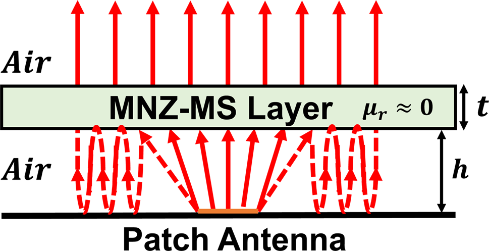
The fundamental idea of the gain enhancement is depending on the fact that introducing a flat lens ahead an antenna to achieve a uniform phase front in the transmitting plane of it. An assortment of zero n-index, ENZ, and MNZ MS unit cells are used for spherical wave into a plane wave conversion as mentioned in [Reference Shaw, Bhattacharjee and Mitra17, Reference Zhou and Li19, Reference Dadgarpour, Kishk and Denidni28]. Integrating a media as an artificial magnet with minimal permeability above of microstrip patch antenna with the appropriate thickness and height behaves like a spatial filter as shown in Fig. 1. To realize the suggested idea, we have chosen a conventional microstrip patch as a source antenna stacked by the MNZ-MS layer to achieve a good gain improvement. Consider an MS layer constructed of an MNZ material with effective permittivity (ɛeff), and permeability (μeff). For a generally incident EM wave which scatters from an MS layer of a thickness (t) into free space, the total transmission coefficient (S 21) that pass out of the slab is easily realized using Maxwell's equations and is given by (1) and (2) [Reference Ramaccia, Scattone, Bilotti and Toscano21, Reference Erentok, Luljak and Ziolkowski30]:


where Z MNZ is the effective impedance of the MNZ slab, Z 0 = 377 Ω is the free-space impedance, (γ) is the propagation constant of the MNZ-MS slab, μr′ and μr″ are the effective real and imaginary relative permeability of the MNZ slab, respectively, and ɛr′ and ɛr″ are the effective real and imaginary relative permittivity of the MNZ slab, respectively.
The mechanism of gain enhancement using MNZ-MS layer.

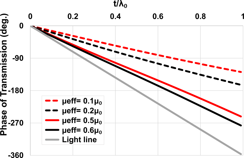
The phase of the overall transmission coefficient (S 21) is estimated concerning the electrical thickness of the MNZ layer (t/λ 0) for various values of (μeff) as reported in Fig. 2. According to the curves, for an incident EM wave, the total transmission phase is lowered in the region of MNZ behavior. So, as expected, in the MNZ slab the phase is shifted lower than in free space for the same propagation distance. Thus, the phase restitution in the patch aperture is provided in the MNZ region, resulting in an enhancement of the antenna gain and directivity. In the restriction μeff → 0, the layer scatters back out-of-phase all the field components of the incident wave (as a perfect-electric-conductor), but only the component that incident normally to the layer is predicted to be completely transmitted out of the layer. For the actual case, the permeability is not precisely zero, so the angular components range that can be transmitted out of the layer is broadening. We suppose that dealing with the effective permeability value of MNZ-MS, the space between the source antenna and the MNZ slab can be used to tune the angular components range that is transmitted through the slab.
The transmission coeff. phase out of an MNZ layer for various values of μeff with respect to the electrical thickness t/λ₀.

On the other hand, to make good use of the field components that reflect from the MNZ slab face, we proposed placing the MNZ slab at a height that constructs a cavity resonator, resulting in multi-reflection of these components and enhancing the gain of all components. Thus, to find the optimum space height (h) between the MNZ-MS layer and the patch we use the same manner that is used for the cavity resonator [Reference Alu, Silveirinha, Salandrino and Engheta20]. As the MNZ slab exhibits a reflection phase of around 180° then for obtaining a good impedance matching with high gain enhancement the height (h) of the slab should satisfy:

where λ 0 is the wavelength in free space at the resonance frequency.
Design of the MNZ-MS unit cell
The target now is to design an MS unit cell that behaves like an MNZ superstrate, to improve the gain of the antenna. By normally incident a plane wave to MNZ slab, the reflection coefficient (S 11) can be calculated using [Reference Erentok, Luljak and Ziolkowski30]:

where Z MNZ is the effective impedance of the MNZ slab, Z 0 = 377 Ω is the free-space impedance, (γ) is the propagation constant of the MNZ-MS slab, and (t) is the MNZ slab thickness. The class of MS under consideration is needed to exhibit a near-zero permeability (μeff), i.e., Z MNZ → 0. Consequently, the reflection coefficient value is:

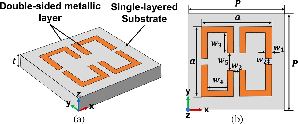
Thus, to obtain the MNZ behavior, low effective permeability is required which can be obtained by extremely high reflection in magnitude with near ±180° reflection phase. To achieve that a configuration of MNZ-MS is proposed as illustrated in Fig. 3. The suggested MNZ-MS unit cell is comprised of a split square resonator designed on Rogers Duroid™ 5880 (εr = 2.2 and tanδ = 0.0009) substrate with a thickness of 1.575 mm as shown in Fig. 3(a). Two rectangular strips are integrated into the split square loop at each of its upper/lower sides as shown in Fig. 3(b), which is used to tune the resonant frequency of the MNZ-MS.
Configuration of the MNZ-MS unit cell (a) 3D view, and (b) Top view, P = 5, a = 4, w 1 = 0.35, w 2 = 0.28, w 3 = 1.25, w 4 = 1.16, w 5 = 0.8, and t = 1.575, (Unit: mm).

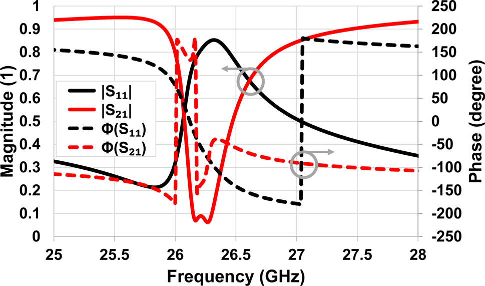
The simulated S 11 and S 21 of the MNZ-MS unit cell are obtained as reported in Fig. 4. The curves indicate that the MS unit cell has a high reflection coefficient better than 0.5 with a reflection phase around −180° over the frequency spectrum of 26.5–27 GHz as desirable. While a transmission coefficient of more than 0.7 over the former frequency range is obtained. To validate the MNZ behavior of the proposed configuration the retrieved effective relative permeability of the MNZ-MS is calculated in accordance with the method proposed in [Reference Luukkonen, Maslovski and Tretyakov31]. The effective refractive index (n) is calculated through:

The simulated S 11 and S 21 of the proposed MNZ-MS.

where k 0 is the free space propagation constant, S 11 and S 21 are the reflection and transmission coefficients of the MS layer, respectively, and (z) is the normalized impedance of the MS and can be calculated by:

Then the relative effective permeability (μeff) is calculated by:

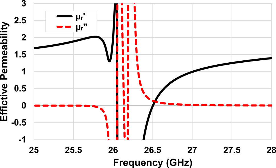
The effective relative permeability (μeff) curves are obtained and reported in Fig. 5. The curves indicate that the real part of the permeability (μr′) is near zero as well as the imaginary part (μr″) is zero over a frequency range of 26.5–26.8 GHz exhibiting MNZ behavior as expected. Thus, the proposed MNZ-MS unit cell is analogous to a meta-lens and could provide a high gain enhancement of the incident EM waves over the former frequency range.
The μeff of the proposed MNZ-MS.

MNZ-MS based antenna configuration
High gain antenna structure and design
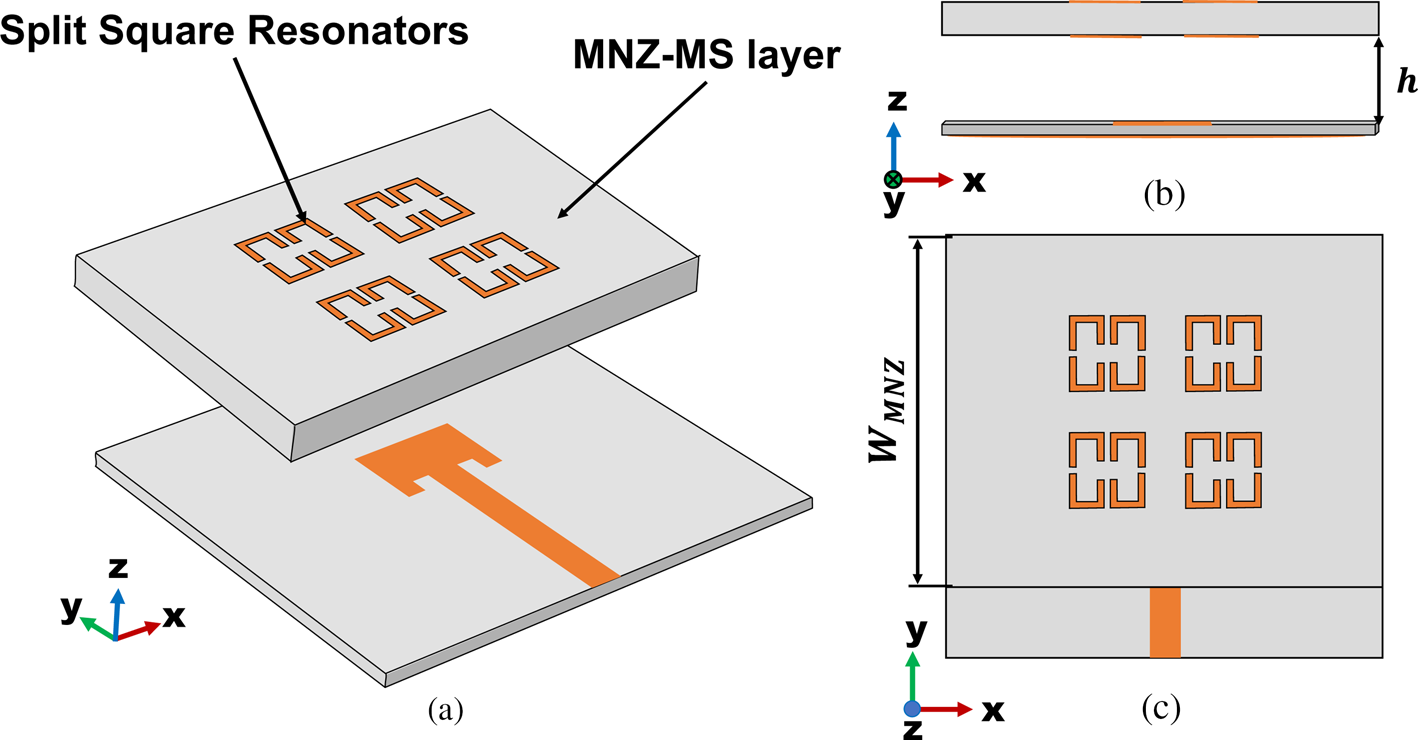
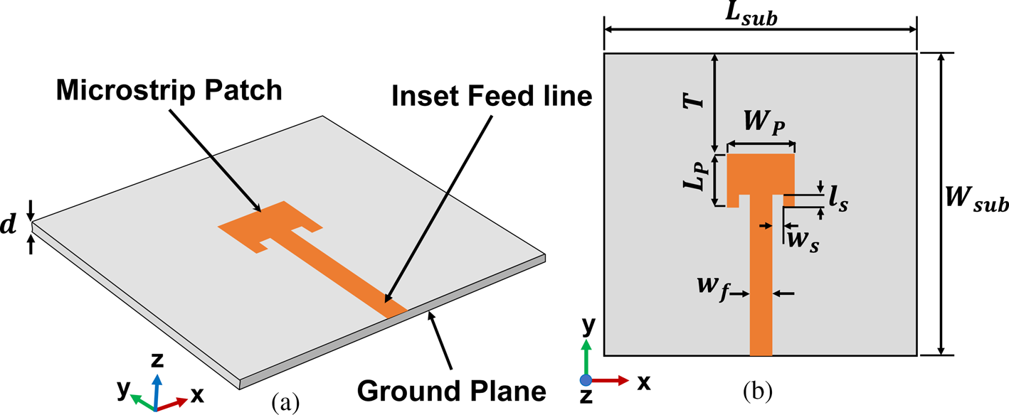
As the patch antenna is utilized in different applications thanks to its simple modeling and manufacturing, hence, the proposed configuration of the MNZ-MS-based antenna is comprised of a patch antenna as a source and a slab of MNZ-MS unit cells as illustrated in Fig. 6 in different views. The configuration of the patch antenna is illustrated in Fig. 7, which has a simple structure with a single-layered substrate (20 × 21 mm), of Rogers-Duroid™ 5880 With a thickness of d = 0.508 mm. The antenna has been designed to work at a frequency of 26.6 GHz. The design equations for the patch are given by [Reference Balanis32]. The antenna is fed by using an inset feeding strategy that does not need any extra matching parts to avoid unwanted impedance mismatch if a conventional 50 Ω line is directly connected. The slab of MNZ-MS unit cells is positioned vertically above the aperture of the patch antenna with an air space of 5.5 mm between the two slabs. The MNZ-MS slab consists of a 2 × 2 assortment of the MNZ unit cells as illustrated in Fig. 6(c).
Configuration of the proposed MNS-MS based antenna (a) 3D-view, (b) Top-view, and (c) Side-view, W MNZ = 17, and h = 5.5, (Unit: mm).

Geometry of the source patch antenna, (a) 3D-view, and (b) Top-view, W P = 4.65, L P = 3.65, T = 6.675, W sub = 20, L sub = 21, W f = 1.4, w s = 0.8, l s = 0.9, d = 0.508 (Unit: mm).

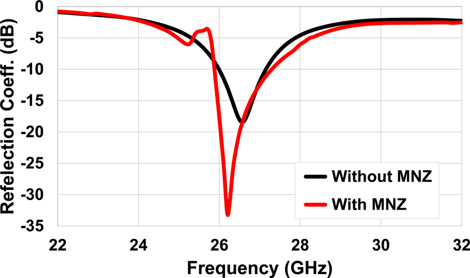
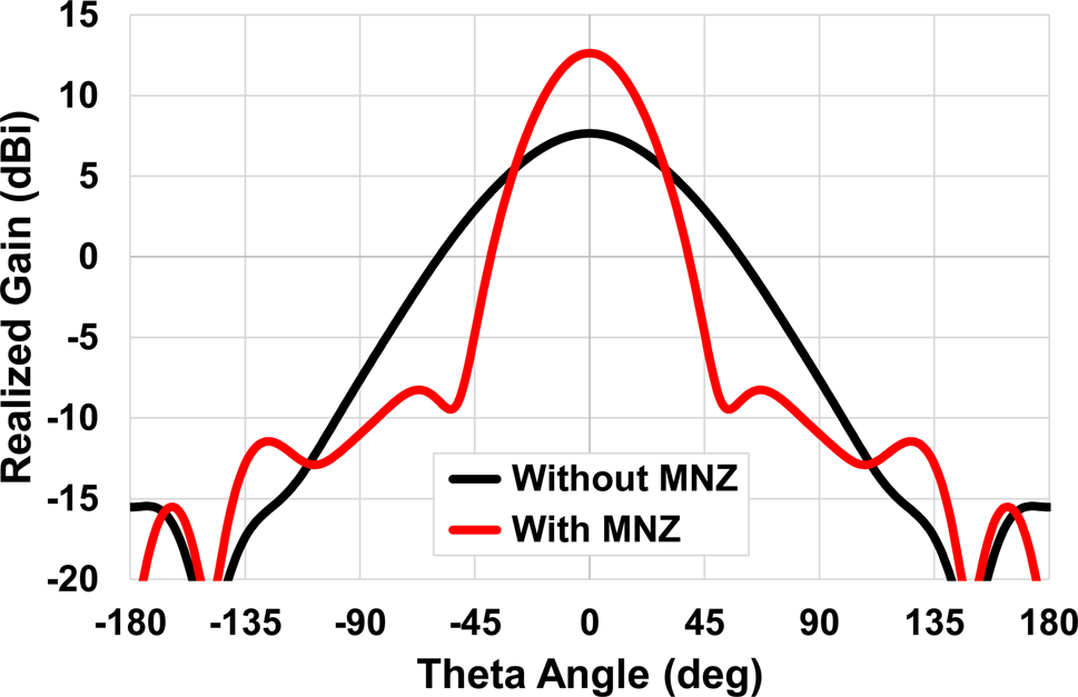
The S 11 of the MNZ-MS based antenna is obtained and reported in Fig. 8. The curves indicate that a good impedance matching of better than −33 dB at the resonant frequency of 26.21 GHz is obtained, with a bandwidth of 1.43 GHz. Also, the antenna gain is studied and compared with the gain of the reference antenna as reported in Fig. 9, the findings exhibit that the suggested antenna enhances the gain by about 5 dB at the resonant frequency.
The simulated S 11 of the suggested MNZ-MS based antenna with and without MNZ-MS slab.

The simulated H-plane gain of the MNZ-MS-based antenna with and without MNZ-MS layer at the resonant frequency.

The height effect
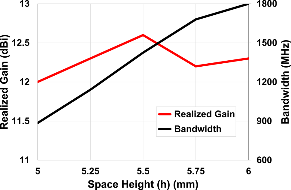
A parametric investigation has been performed to optimize the space height (h) between the MNZ-MS layer and the patch. Firstly, the height of the MNZ slab above the source antenna is initially calculated by inserting the free-space wavelength of the patch antenna (λ 0 = 11.28 mm) in (3), then a primary approximate value of h = 5.6 mm is obtained. Afterward, a parametric sweep around this value is done. The inspection results indicate that the height affects the gain enhancement, the impedance matching, and the bandwidth as well. The realized gain and bandwidth of the MNZ-MS based antenna are plotted for various height values as illustrated in Fig. 10. The curves indicate that the bandwidth is increased as the height (h) is increased, while the highest possible gain of 12.6 dBi is achieved at h = 5.5 mm with a suitable wide bandwidth of order better than 1.43 GHz. It is worth mentioning that only one slab is used to make the antenna size as compact as possible.
The simulated gain and bandwidth of the MNZ-MS based antenna for different values of spacing height (h).

Antenna performance and results
Simulation results
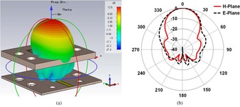
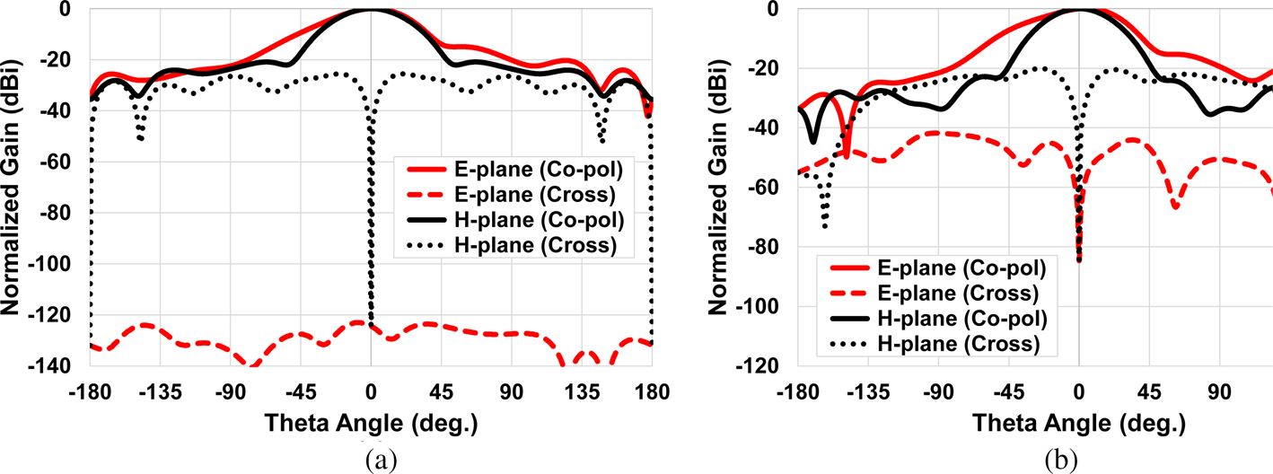
The E-plane and H-plane radiation patterns of the antenna at the frequency of 26.3 GHz are investigated as illustrated in Fig. 11. The figures show that the sidelobe level of the MNZ-MS based antenna is better than −15 dB and the front-to-back ratio is more than 20 dB at the resonance frequency. The antenna simulated co-polarization and cross-polarization are obtained at 26.3 GHz utilizing two different simulation programs (CST Microwave Studio and ANSYS HFSS electromagnetic field simulator) as reported in Fig. 12. It is evident from the curves that the antenna is perfect linear polarization with cross-polarization isolation of better than −80 dB, proving that the MNZ-MS layer does not affect the antenna polarization.
The simulated far-field gain (dBi) of the MNZ-MS based antenna, (a) 3D radiation pattern, and (b) The normalized 2D radiation patterns.

The simulated normalized co-polarization and cross-polarization far-field patterns of the MNZ-MS based antenna @ 26.3 GHz (a) Using CST, and (b) Using HFSS.

Furthermore, the radiation efficiency (e cd) is obtained according to the ratio of the simulated gain and directivity, which corresponds to 93.9% at the frequency of 26.3 GHz. Also, the total efficiency (e 0) is calculated using:

where Γ is the reflection coefficient of the antenna, whereas a simulated total efficiency of 93.4% is obtained at the former resonant frequency.
Experimental results
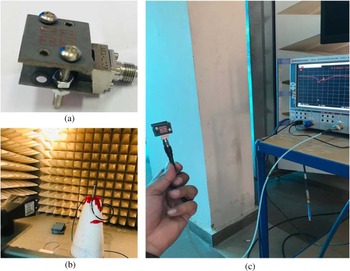
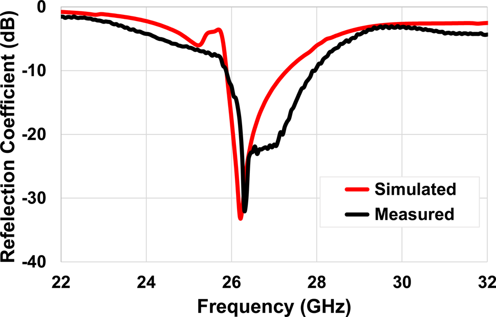
To validate the proposed MNZ-MS based antenna functioning for gain enhancement, the antenna prototype model has been designed and manufactured. The photos of the fabricated prototype MNZ-MS based antenna after assembly and photos during measurement procedures are illustrated in Figs 13(a)–13(c). The R&S ZVA 40 vector network analyzer (VNA) is utilized to measure the return loss of the antenna. Figure 14 shows the corresponding S 11 simulated and measured results. The curve signifies that there is a good consent between the results, and a good impedance matching over 26–28 GHz is achieved with a 2 GHz of bandwidth.
Photos of the fabricated MNZ-MS based antenna measurements (a) 3D view of the assembled antenna prototype, (b) Gain measurement, and (c) Reflection coefficient measurement.

The measured and simulated reflection coefficients (dB) of the MNZ-MS based antenna.

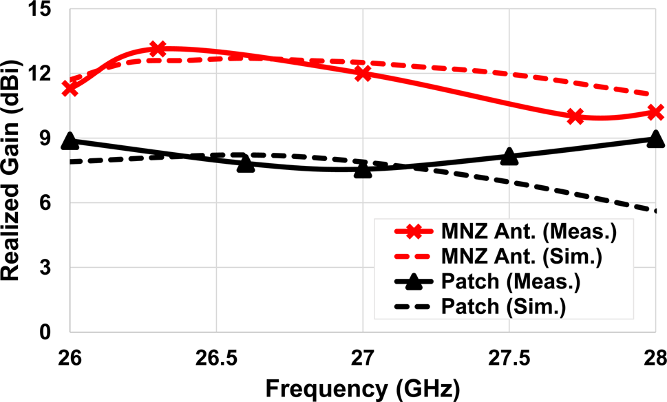
On the other side, the realized gain of the source patch and the proposed antenna are measured as a function of the operation frequency and reported in Fig. 15. The curves show that the MNZ-MS based antenna achieves a gain improvement of better than 5 dB at 26.3 GHz in comparison to the source antenna. It is worth mentioning that the gain measurement procedure was performed depending on the method of three antennas. In this technique, two various antennas (working at the same bandwidth) were used in addition to the antenna under test. The technique is depending on measuring the power received from the transmitting antenna utilizing every couple of the three antennas which is computed by:

where Gj and Gi refer to the gain of the two various antennas evaluated during testing #n (n = 1, 2, 3), Pr and Pt are the receiving and transmitting power, R is the distance between the antennas, and λ is the operating wavelength.
The realized gain (dBi) of the source patch only and the MNZ-MS based antenna versus frequency.

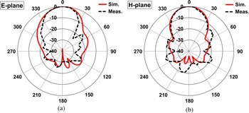
The measuring was performed at a constant distance (sufficient to meet the far-field condition) among transmitting and receiving antennas. Thus, this technique permits the estimate of the gain of the three antennas. More detailed information on the technique can be found in [Reference Balanis32]. Furthermore, the measured radiation patterns in the E-plane and H-plane are obtained at a frequency of 26.3 GHz as illustrated in Fig. 16. According to the findings, we can argue that the little differences between the simulation and measurements were mainly, because of the fabrication procedures tolerance and the non-prevented losses during the measurements like for example the SMA connector reflection, as its size is comparable to the size of the antenna. In summary, the MNZ-MS based antenna performances on the topic of gain, resonant frequency, bandwidth, and efficiency are reported in Table 1.
The normalized radiation pattern of the MNZ-MS based antenna at the resonant frequency of 26.3 GHz (a) E-plane, (b) H-plane.

Comparison of the performances of the proposed MNZ-MS based antenna regarding the reference antenna

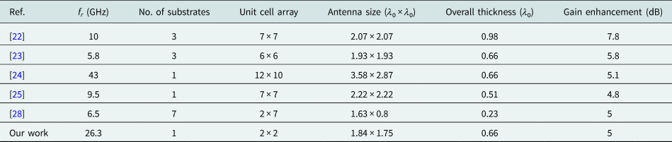
After All, the comparison between the suggested antenna and the recent prior works on the topic of gain enhancement is tabulated in Table 2. The comparison indicates competitive performances for the suggested antenna in terms of compactness, low profile, and good gain enhancement. However, the designs in [Reference Li, Szabó, Qing, Li and Chen22–Reference Bouzouad, Chaker, Bensafielddine and Laamari24] achieve a gain enhancement better than our antenna, the designs have large antenna sizes in addition to using many unit cells with multi-layers of substrates. Furthermore, our antenna achieves a good gain enhancement using a single substrate of 2 × 2 MS unit cells, which is better than [Reference Hou, Su and Zhao25, Reference Dadgarpour, Kishk and Denidni28].
Comparison of the MNZ-MS based antenna with respect to the previous works

Conclusion
The MNZ-MS based antenna with high gain and wideband has been introduced over the frequency band of 26–28 GHz for future 5G applications. The proposed antenna consists of an MNZ-MS slab above a microstrip patch antenna. The antenna has been studied and fabricated. The gain enhancement functionality has been achieved with a gain enhancement of more than 5 dB. The operating frequency band, gain enhancement, and radiation patterns have been studied and discussed. A single wideband antenna with a high gain of 13.13 dBi is achieved at 26.3 GHz. Besides, the cross-polarization isolation of the proposed MNZ-MS based antenna is good, which is making it a good nominee for the new 5G wireless communication systems.
 Islam H. Abdelaziem was born in 1993. He obtained the B.Sc. degree, with a GPA of 3.65 out of 4 with honors, in electronics and communication engineering from the Electrical Engineering Department, Faculty of Engineering, Sohag University, Sohag, Egypt in 2016. He was awarded the M.Sc. degree in electronics and communications engineering from the Electronics and Communication Engineering Department, Minia University, El-Minia, Egypt in 2021. He has been with the Sohag Faculty of Engineering since 2017 where he is now an assistant lecturer with the Electrical Engineering Department, Sohag University. His research interests include metasurface-based antennas, dual-band, and multi-band antennas, frequency reconfigurable antennas, polarization reconfigurable antennas, high gain antennas, gain enhancement techniques, microwave engineering, and future 5G applications.
 Ahmed A. Ibrahim (M'19, SM'20) was born in 1986. He received the B.Sc. degree, and M.Sc., Ph.D. in electrical engineering from the Electronic and Communication Engineering Department, Minia University, El-Mina, Egypt in 2007, 2011, and 2014 respectively. He is now an associate professor in the Electrical Engineering Department in the Faculty of Engineering Minia University. He has been a visiting professor at University Pierre and Marie Curie, Sorbonne University, Paris VI, France for 7 months and Otto-von-Guericke-Universität Magdeburg-Germany for 6 months. He has published more than 95 peer-reviewed journals and conference papers. His research has focused on miniaturized multiband antennas/wideband, microwave/millimeter components, DRA metamaterial antenna, graphene antenna, and microwave filters. Also, his research includes MIMO antennas and energy harvesting systems. Dr. Ahmed A Ibrahim is a senior member of the IEEE and a senior member in URSI also a member of the national committee of radio science in Egypt. He is currently a reviewer in, IEEE Antennas and Wireless Propagation Letters, IEEE Microwave Wireless Components, IEEE access, IET Microwave, Antenna and Propagation, IET Electronics Letters, MOTL, Analog Integrated Circuits, and Signal Processing, and many other journals and conferences. In 2020, and 2021 he was named in the top 2% of scientists in “A standardized citation metrics author database annotated for scientific field”/“Updated science-wide author databases of standardized citation indicators”.
 Mahmoud A. Abdalla (M'09, SM'15) obtained the B.Sc. degree, with a grade of excellent with honors, in electrical engineering from the Electronic Engineering Department, Military Technical College, Cairo, Egypt in 1995. He was awarded the M.Sc. degree in electrical engineering from Military Technical College in 2000, and the Ph.D. degree from microwave and communication group, School of Electrical Engineering, Manchester University, UK, in 2009. He has been with Military Technical College since 1996 where he is now a professor, the head of the Department Council Committee, and the electromagnetic waves/microwave group in the Electronic Engineering Department. He is a recognized international authority in the society of electromagnetics. He has published more than 200 peer-reviewed journal and conference papers His research has focused on different metamaterial applications in microwave and millimeter bands especially microwave components, miniaturized multiband antennas, and ferrite components. Dr. Mahmoud is a senior member of the IEEE/URSI and the European Microwave Association EuMA. Dr. Abdalla is currently a reviewer in many electromagnetic journals such as IEEE Antennas and Wireless Propagation Letters, IEEE Transaction in Magnetics, Applied Physics, and the International Journal of Microwave and Wireless Technologies. Prof. Mahmoud Abdalla was the recipient of the Egyptian encouragement state prize award for engineering sciences in 2014. In 2019, he was the recipient of the Egyptian El-sherouq innovation award in electronic engineering. He was awarded the top 1% Publon worldwide reviewer award for 2018 and 2019. In 2020, he was named in the top 2% of scientists in “A standardized citation metrics author database annotated for scientific field”/“Updated science-wide author databases of standardized citation indicators”.