Introduction
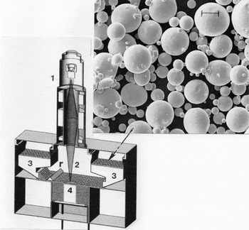
Electron-beam melting (EBM) has recently become one of the standard additive manufacturing technologies for metals. Commercial EBM systems are available to a limited extent, currently dominated by Arcam AB, Sweden. The Arcam EBM system, illustrated schematically in Figure 1 , relies on gravity feed of an optimized metal (or alloy) powder (Figure 1 inset), usually prepared by rapid solidification processing. Powders in cassettes flow by gravity onto a raked bed where the electron beam is selectively scanned using computer-aided design (CAD) software to heat and melt each raked layer; these usually consist of roughly three powder particle diameters in thickness. As each raked layer is selectively melted, the build platform drops down by a layer thickness (usually 50–100 μm) and a new powder bed is formed; the process is then repeated.
Schematic view of Arcam electron-beam melting (EBM) system. The inset shows a scanning electron microscope (SEM) image of Inconel 625 (Ni-based superalloy) powder typical of precursor powders for EBM. (1) The electron gun (60 kV) and electron optical system; (2) the scanning electron beam; (3) powder cassettes; (4) the build product table. Note: r, powder rake. Magnification marker in the SEM image is 40 μm.

In the Arcam system, the build volume (in vacuum) is limited to about 0.03 m3, which allows only small product fabrication. In addition, many high-temperature metal products require pre-alloyed powders, and fabricated products requiring intricate internal structures must be designed to allow the unmelted powder to be conveniently removed. Consequently, closed cellular structures cannot be fabricated since unmelted powder remains within the closed cells.
In this article, we examine the fundamental aspects of additive EBM fabrication, including process optimization and limitations. Selective examples of EBM processing of high-temperature metals and alloys include (with their melting points in parentheses) Ti-6Al-4V (1630°C), the Ni-based superalloy René 142 (1375°C), and Fe (1537°C). These metals represent hexagonal close-packed (hcp), face-centered-cubic (fcc), and body-centered-cubic (bcc) crystal structures, respectively. These metals are used in a range of products and applications, including aerospace components (Fe, Ti-6Al-4V and Ni-based superalloys), orthopedic appliances (Ti-6Al-4V), turbine system components (René 142), and special property components such as magnetic materials (Fe).
Fundamental issues in contemporary EBM: Process control and optimization
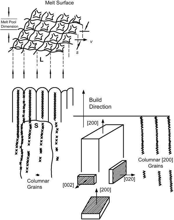
The melt (L)–solidification (S) process characteristics of powder bed-layer additive manufacturing by EBM are shown in Figure 2 . The local temperature in the layer thickness (t) can be represented generally by:
 $$T = Q\left( {1 - R} \right)/\rho {C_p}t,$$
where Q is the power density, R is the electron reflectivity, Cp is the heat of fusion, and ρ is the powder bed density, which increases with melting of the scanned layer. It can be envisioned that EBM process optimization will involve the beam scan speed (v), the power density (Q), and the beam focus (beam radius, r), where:
 $$Q = {{{\rm{power}}\,{\rm{absorbed}}} \over {2\pi {r^2}t}},$$
as well as the scan strategy (speed, direction, size, and current of the electron beam), Reference Bontha, Klingbeil and Kobryn1 including preheating of the powder bed and variations in the melt scan or scan direction (x, y). Scan-strategy variations will correspondingly influence the distance between scan lines (s in Figure 2) or their overlap.
Schematic rendering of melt (L)–solidification (S) growth in electron-beam melting, which can promote columnar (directional) microstructures. Preferred crystal orientations for face-centered-cubic metals and alloys are also shown. Note: v, scan speed; s, scan lines.

When the beam is scanned in the x- and y-directions (in the plane perpendicular to the build [z] direction), a melt pool develops with the corresponding scan dimension (s in Figure 2) and, with repeated melt-solidification events in successive powder layers, columnar microstructures can develop, as illustrated schematically in Figure 2. As a result of the localized thermokinetics within the melt pool (Figure 2), novel microstructures can develop within columnar grains to form unique architectures. The lower right image in Figure 2 also shows that columnar grains can adopt preferred orientations, often characteristic of minimum energy directions corresponding to specific crystal unit cells: [002] for fcc and [110] for bcc. However, there are often subtle variances in the beam scan (e.g., speed, spacing) and impurities in the powder layer that will interrupt the columnar, preferred crystallographic growth. For hcp crystal structures, preferred orientations are less common than more equiaxed or truncated microstructures.
Powder purity, morphology, and particle-size distribution are important issues in optimizing the EBM process. The scanning electron microscope image in Figure 1 shows a typical example of a high-temperature metal powder (in this case, the Ni-based superalloy Inconel 625). Preferred powder particles are spherical and their size distribution (as shown in Figure 1) allows effective filling of interstitial volumes in the raked powder bed. This process is also characterized by the particle flowability. In addition, impurities and impurity particles in the powder create beam tripping (where the beam is instantaneously interrupted), often resulting in poorly melted regions, while excess water vapor or oxidation of powders can hinder the melt formation.
In some cases, prebaking of the powders in vacuum and transfer under inert atmospheres can improve the powder melt efficiency. Preheating the powder layers by beam scanning prior to the melt scan is also a crucial step in assuring efficient melting. Gaytan et al. Reference Gaytan, Murr, Medina, Martinez, Lopez and Wicker2 explored many issues relating to beam power, scan speed, and other build parameters, including melt efficiency and the reuse of powders such as Ti-6Al-4V. They described a quality control concept to examine and certify products nondestructively. Gong et al., Reference Gong, Anderson and Chan3 Smith et al., Reference Smith, Derguti, Hernandez Nava, Thomas, Tammas-Williams, Gulizia, Fraser and Todd4 Korner, Reference Korner5 and several other recent review articles summarize many of these features and manufacturing advances by EBM over the past decade.
Examples of high-temperature metals fabricated by EBM
Ti-6Al-4V
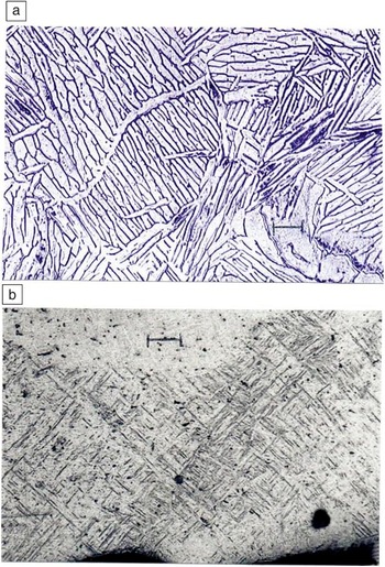
Ti-6Al-4V is perhaps the most widely EBM-fabricated high-temperature metal because of its applications in aerospace components and a variety of biomedical components that require quick and adjustable design. Reference Gaytan, Murr, Medina, Martinez, Lopez and Wicker2–Reference Murr, Amato, Li, Tian, Cheng and Gaytan7 This hcp alloy is essentially a two-phase (α [hcp] + β [bcc]) system that nominally appears as a lenticular α grain structure with β regions in the α grain interfaces as shown in Figure 3a. This structure is temperature (or cooling rate) sensitive, and for product fabrication involving small volumes or thin sections that cool rapidly, α becomes thinner and begins to transform to αʹ as implied in Figure 3b. αʹ dominates in open cellular structures such as mesh and foam geometries. Reference Murr, Gaytan, Medina, Lopez, Martinez and Machado6 These structures are precursors to the development of a variety of orthopedic implants Reference Murr, Gaytan, Medina, Lopez, Martinez and Machado6 as well as other components with complex internal structures, such as heat exchangers, where the EBM fabrication strategy allows for convenient removal of internal unmelted powder.
Optical microscope views of electron-beam melting fabricated Ti-6Al-4V components. (a) Double-melt scan to produce large, lens-like α grains (hexagonal close-packed) surrounded by a thin (dark) β (body-centered-cubic) phase. (b) Rapidly cooled thin component section producing closely spaced αʹ platelets (dark). Magnification markers are 25 μm.

It can be noted on comparing Figure 3a–b that obvious microstructure refinement, which can occur as a reduction in the spacing between α and αʹ platelets (from 8 µm to 1 µm [Figure 3a–b]). This results in an increase in microindentation hardness by more than 40%. Corresponding increases in yield strength are also accompanied by a decrease in elongation.
René 142 Ni-based superalloy
In the development of commercial Ni-based superalloys for directionally grown (cast) turbine blades, cuboidal γʹ (Ni3 (Al, Ta)) precipitates have played a crucial role. Reference Korner5 In these alloys, cuboidal Ni3 (Al, Ta) fcc γʹ precipitates fill the directionally grown blade, and their cuboidal geometry and size relative to their spacing in the fcc Ni-Cr matrix can be engineered (through various heat treatments) to control deformation, especially creep deformation, which begins in the fcc Ni-Cr matrix and then propagates into the Ni3 (Al, Ta) cuboidal precipitates.
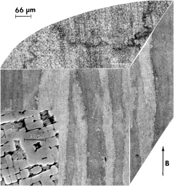
Figure 4 shows a low-magnification, three-dimensional (3D) section view of a Rene 142 Ni-based superalloy (12Co, 6.8Cr, 6.35Ta, C.15Al, 4.9W, 2.8Re, 1.5Mo, 1.5Hf, balance Ni) powder-EBM-fabricated product containing columnar grains growing in the build direction (B). In contrast to the random powder orientations, the vertical and horizontal (plane) sections are strongly (200) and (220) oriented corresponding to Figure 2. Magnified views of 3D sections within the oriented (columnar) grains show the cuboidal γʹ precipitates (Figure 4 inset). As discussed by Oblak and Kear, Reference Oblak, Kear, Thomas, Fulrath and Fisher8 a higher magnification view in the transmission electron microscope (TEM) ( Figure 5 ) illustrates the unique coherent {100} interfaces separating the γʹ cuboids from the fcc Ni-Cr matrix, where a high density of dislocations accommodate some of the coherent interface strain.
3D sectional view of a René 142 Ni-based superalloy component exhibiting columnar 〈200〉 grains containing cuboidal γʹ phase (face-centered-cubic [fcc]) Ni3 (Al, Ta) precipitates shown in the scanning electron microscope image inset. Precipitates are separated by fcc Ni-Cr (γ phase). Note: B, build direction (the z-direction in Figure 2). Reference Oblak, Kear, Thomas, Fulrath and Fisher8

Transmission electron microscope image showing coherent γ/γʹ cuboidal precipitates in René 142 alloy components shown in the scanning electron microscope inset in Figure 4. Reference Oblak, Kear, Thomas, Fulrath and Fisher8

It is interesting to note Reference Murr, Martinez, Pan, Gaytan, Castro, Terrazas, Medina, Wicker and Abbott9 that EBM-fabricated René 142 components contain essentially optimized γʹ cuboidal size as well as the fcc Ni-Cr (γ) matrix thickness separating the γʹ cuboids. This additive manufacturing process, involving a standard layer preheat scan sequence and the melt scan sequence, fortuitously skips complex annealing schedules normally employed in developing optimized, commercial René 142 turbine blades.
Iron
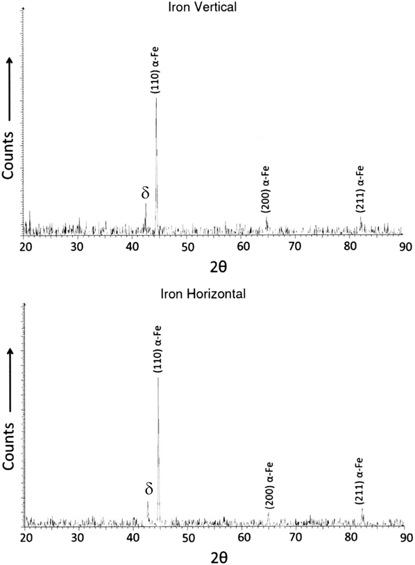
While Figures 4 and 5 illustrate an example of an fcc, high-temperature superalloy fabricated by EBM, Figure 6 shows a 3D section view of bcc iron fabricated by EBM. The relatively equiaxed ferrite grain structure shows unusual δ iron precipitates within the bcc (α, ferrite) grains. This nonequilibrium high-temperature (quenched) phase is retained from the rapidly solidified, atomized ferrite-iron powder (Fe, 99.9%, 0.05%°C). Reference Murr, Martinez, Pan, Meng, Yang, Li, Yang, Xu, Hernandez, Zhu, Gaytan, Medina and Wicker10 The ferrite grains are strongly textured with platelets in the [110] direction, as seen in the x-ray diffraction spectra in Figure 7 .
Equiaxed ferrite (body-centered-cubic [bcc]) grains in a pure iron electron-beam melting component containing δ-phase (bcc) nonequilibrium phase platelets. Note: B, build direction. Reference Murr, Martinez, Pan, Meng, Yang, Li, Yang, Xu, Hernandez, Zhu, Gaytan, Medina and Wicker10

X-ray diffraction spectra corresponding to Figure 6 showing prominent α and δ peaks in vertical and horizontal plane sections. Reference Murr, Martinez, Pan, Meng, Yang, Li, Yang, Xu, Hernandez, Zhu, Gaytan, Medina and Wicker10

The bcc δ phase occurs as thin, irregular platelets coincident with the ferrite {110} and {100} planes.
Figure 8
shows a TEM image of a (111) plane where the δ phase is coincident with the [1
 $\bar 1$
0] and [
 $\bar 1$
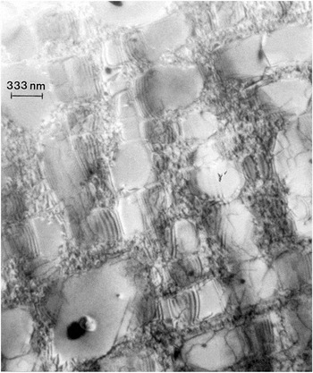
01] directions shown by A and B, respectively. Extended screw dislocations are also prominently featured in the microstructure in Figure 8. For more details about EBM microstructure in solid iron and open cellular structures, see Reference Reference Murr, Martinez, Pan, Meng, Yang, Li, Yang, Xu, Hernandez, Zhu, Gaytan, Medina and Wicker10.
Transmission electron microscope image of a ferrite (111) grain showing irregular δ-phase platelets coincident with the A [1
 $\bar 1$
0] and B [
 $\bar 1$
01] directions. The operating reflection is shown at g. Note: GB, grain boundary.
Reference Murr, Martinez, Pan, Meng, Yang, Li, Yang, Xu, Hernandez, Zhu, Gaytan, Medina and Wicker10

Summary
We have presented a short review of the EBM process along with a few examples of high-temperature metals fabricated by EBM. The fabrication of Ti-6Al-4V is characterized by microstructures already well known metallurgically: α + β; α + β + αʹ. In the case of René 142, a Ni-based superalloy characterized by columnar grains with low-angle boundaries, γʹ Ni3 (Al, Ta) cuboidal precipitates, well known metallurgically since the 1960s, are dominant. In addition, EBM processing produces optimized cube dimensions of 275 nm, spaced by 50 nm in the fcc matrix. In EBM-fabricated iron, however, anomalous δ iron platelets are observed, a microstructure rarely observed in more conventional, equilibrium iron processing.
While EBM fabrication has become an attractive additive manufacturing process for small, high-temperature metal products, including complex geometries and even one-of-a-kind (customized) products, it remains constricted by precursor powder costs (up to 10× solid metal cost) and processing. The inability to fabricate complex, closed-cell structures where unmelted powder cannot be removed also remains a process limitation.
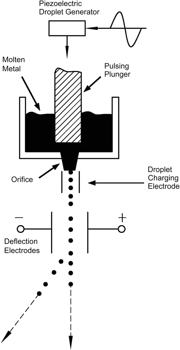
Since the 1990s, there have been a number of investigations aimed at creating metal microdroplets that can be selectively deposited using CAD software to fabricate products by a true 3D printing process. Reference Orme11–Reference Chao, Qi, Xiao, Luo and Zhou15 Figure 9 illustrates this concept schematically. Until now, high-temperature metals have evaded such processing, but innovations in direct metal printing head development may someday allow multiple metal deposition from large gantry designs in inert gas or vacuum environments, with the capability to print large structures and components using auxiliary electron and laser beams for pre- and postprocessing.
Schematic diagram representing direct metal droplet deposition described conceptually by Orme and Smith. Reprinted with permission from Reference Reference Orme and Smith12. © 2000 The American Society of Mechanical Engineers.

Acknowledgments
This research was supported in part by The University of Texas at El Paso, Office of Research and Sponsored Projects, and the National Basic Research Program of China (2012CB933901) and the National Natural Science Foundation of China (51271182).