I. INTRODUCTION
Cassegrain reflector antennas are widely used in satellite communication, radar applications, remote sensing, radio astronomy, etc. These antennas are characterized by their highly directive nature, and relatively large aperture efficiency. Demand for Cassegrain reflectors has resulted in the development of numeric and analytic techniques for design and analysis of such antennas [Reference Rahmat-Samii and Volakis1, Reference Balanis2].
A Cassegrain antenna consists of a feed antenna, a hyperboloidal subreflector, and a paraboloidal main reflector. When the antenna is used as a transmitter, the electromagnetic radiation from the feed antenna, which is usually a horn antenna, is directed toward the subreflector. The subreflector is said to be illuminated by the feed antenna. The subreflector scatters the incident field and in doing so, illuminates the main reflector. The main reflector creates the far-field radiation pattern of the antenna. The far-field pattern from the main reflector is called the secondary pattern and the radiation pattern of the feed antenna is known as the primary pattern [Reference Silver3]. The secondary pattern depends on the geometry of the Cassegrain system, and the primary pattern [Reference Silver3, Reference Baars4].
Several methods exist for formulating the far-field of a Cassegrain reflector. Geometrical optics (GO), uniform geometrical theory of diffraction (UTD), physical optics (PO), and physical theory of diffraction (PTD) are widely used numerical methods for large Cassegrain antennas [Reference McNamara, Pistorius and Malherbe5]. These methods are sufficiently accurate, but they require lengthy calculations and tedious computer coding. In many cases, only the main lobe region near the bore-sight of the Cassegrain antenna needs to be calculated, as the far-off sidelobes have very small values [Reference Baars4]. Sufficiently accurate results for the near main lobe region can be obtained by using justified approximations. These approximation methods can provide a simpler alternative for estimating the far-field region near the bore-sight of the antenna.
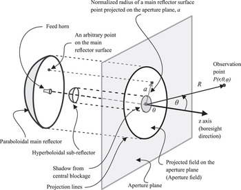
The aperture field (AF) integration method provides an opportunity to use approximation techniques to derive closed-form expressions for the far-field region [Reference McNamara, Pistorius and Malherbe5, Reference Yaghjian6]. In the AF integration method, the fields reflected by the main reflector are approximated by GO rays. The reflected rays from the main reflector are projected upon an infinite plane. This plane is called the aperture plane of the antenna [Reference Rahmat-Samii and Volakis1, Reference Baars4]. The aperture plane is usually assumed to go through the focus of the paraboloid. The observation point P is taken to be far away from the aperture plane. A Cassegrain antenna along with its aperture plane is shown in Fig 1. The projected field on the aperture plane is known as the AF of the antenna. The aperture of the antenna is defined as the projected surface of the main reflector on the aperture plane. The AF outside the aperture is approximated as zero [Reference Rahmat-Samii and Volakis1]. The radiation integral over the curved surface of the main reflector can equivalently be performed over the aperture plane of the antenna. This method is known as the AF integration method.
Apeture plane of a Cassegrain antenna.

By knowing the field distribution on the aperture of the antenna, the far-field pattern can be calculated using AF integration [Reference Yaghjian6, Reference Bucci, Franceschetti and Pierri7]. The AF depends on the primary pattern and the subreflector surface geometry. In an unshaped Cassegrain system, the subreflector is a hyperboloid. In such cases, only the primary pattern determines the AF. In most cases, the feed antenna is a horn antenna, such as a conical corrugated horn or a potter horn [Reference Rahmat-Samii and Volakis1]. The AF resulting from these types of feeds can be modeled by mathematical functions containing a few parameters. These functions are known as illumination functions [Reference Zaman, Choudhury, Gaffar and Matin8, Reference Richardson9]. The accuracy of the AF integration depends on how well the illumination function represents the actual AF distribution.
It can be seen from Fig 1 that a part of the aperture of the antenna is shadowed by the subreflector. This is known as the central aperture blockage. Owing to the aperture blockage, the AF in the shadowed region has smaller value. This reduction in AF value causes the overall gain of the antenna to decrease [Reference Baars4, Reference Pace10]. Aperture blockage may also be created by subreflector supports [Reference Lamb and Oliver11]. However, compared with the subreflector blockage, these blockages are negligible. To correctly approximate the AF, the illumination function must take into account this aperture blockage. The illumination functions covered in the literature have not taken aperture blockage into consideration [Reference Zaman, Choudhury, Gaffar and Matin8, Reference Richardson9]. The effect of gain reduction due to aperture blockage using illumination function correction is discussed in [Reference Solovey, Cardiasmenos and Mittra12]. However, an illumination function taking into account the aperture blockage is not defined in [Reference Solovey, Cardiasmenos and Mittra12]. Also, the far-field radiation pattern was not formulated in [Reference Solovey, Cardiasmenos and Mittra12]. In this paper, a novel illumination function is defined that takes into account the aperture blockage created by the subreflector. Using this new illumination function, the AF integration is performed and a closed-form expression of the far-field radiation pattern is obtained. The derived expressions relate the aperture blockage to the radiation pattern directly. The obtained results are compared with the results obtained from the PO method and the PO + PTD methods, and are found to be consistent. The PO + PTD method uses a better approximation for the surface current density compared with the PO methods [Reference Rahmat-Samii and Volakis1, Reference McNamara, Pistorius and Malherbe5]. This results in better accuracy. However, it is computationally more demanding compared to the PO method. As the PO and PO + PTD methods are generally accepted methods for far-field analysis of reflector antennas, the consistency of the derived results with the results obtained from these methods verifies the analysis.
The paper is organized as follows: Section II covers the geometry of the Cassegrain reflector, the illumination function is derived in Section III, Section IV contains the AF integration and far-field formulation, the numerical results are provided in Section V, and Section VI contains the concluding remarks.
II. GEOMETRY
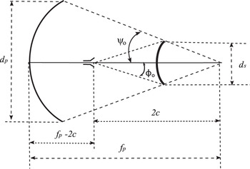
The two-dimensional geometry of a Cassegrain antenna is shown in Fig 2. The following parameters are shown in Fig 2:
d p = diameter of the main reflector,
d s = diameter of the subreflector,
f p = focal length of the paraboloid,
2c = distance between foci of the hyperboloid,
ψo = opening half angle of the paraboloid, and
ϕo = opening half angle of the hyperboloid.
Geometry of the Cassegrain reflector.

The hyperboloidal subreflector has two focal points. One of the focal points coincides with the phase center of the feed horn and the other coincides with the focal point of the paraboloid [Reference Baars4]. The relation between the geometrical parameters can be found in [Reference Granet13].
To employ AF integration, it is necessary to project the main reflector surface on the aperture plane. For convenience, the aperture plane is assumed to go through the focal point of the main reflector [Reference Balanis2, Reference Baars4]. The angle ψ o is created between the axis of the reflector and the line joining the focal point and edge of the main reflector. In general, angle ψ can be defined for any arbitrary point on the reflector surface. This angle varies from –ψ o to +ψ o. The normalized radius of a main reflector surface point projected on the aperture plane, a, can be related to the geometrical parameters as [Reference Baars4]:
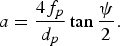 $$a=\displaystyle{{4f_{p} } \over {d_{p} }}\tan \displaystyle{\psi \over 2}.$$
The variable a is depicted in Fig 1. It can be shown that [Reference Baars4]:
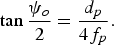 $$\tan \displaystyle{{\psi _{o} } \over 2}=\displaystyle{{d_{p} } \over {4f_{p} }}.$$
From (1) and (2), it is clear that as the angle ψ varies from 0 to ψ o, a varies from 0 to 1. Using (1), each point on the main reflector surface defined by an angle ψ can be mapped into the aperture plane defined by a normalized radius a.
III. DEFINING THE ILLUMINATION FUNCTION
The field distribution on the aperture plane is approximated by an illumination function. The phase distribution of the projected field on the aperture plane is often assumed to be constant [Reference Baars4, Reference Zaman, Choudhury, Gaffar and Matin8]. Well-designed feed horns can produce illumination with constant phase over the entire aperture, thus justifying the assumption. In such cases, the illumination function represents the variation in field amplitude over the aperture. The feed and therefore the resulting aperture distribution are usually circularly symmetric for an axially symmetric geometry. Thus, the illumination function can be expressed by the single independent variable a, and is denoted as A(a).
The illumination function can be modeled as a Gaussian function, a raised-quadratic function, or other higher order polynomial functions [Reference Zaman, Choudhury, Gaffar and Matin8, Reference Richardson9]. These functions represent a field distribution with maximum value near the bore-sight (axis of the reflector) and gradually taper at the edge. The ratio of the field value at the edge of the aperture to the maximum field value at the center of the aperture is known as the edge taper, T. Most illumination functions use the parameter T [Reference Zaman, Choudhury, Gaffar and Matin8]. However, none of the illumination functions found in the literature take into account the decrease in the AF caused by the subreflector blockage.
In this paper, a new illumination function is defined as
 $$A\lpar a\rpar =\left\{\matrix{g\lpar a\rpar \comma \; \quad - a_{e}< a< a_{e} \hfill \cr f\lpar a\rpar \comma \; \quad {\rm otherwise} \hfill} \right.$$
Here, a e is defined as the normalized radius of the aperture that is shadowed by the subreflector, f(a) is the illumination function in the region where no aperture blockage has occurred, and g(a) is the illumination function in the shadowed region describing the decreased AF caused by the subreflector blockage. The shadowed region is highlighted in Fig. 1.
Clearly, the parameter a e is dependent on the subreflector diameter and the main reflector diameter. As a = 1 represents the radius of the main reflector (d p/2) and a e is related to the subreflector radius, it can be written intuitively that,
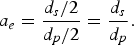 $$a_e=\displaystyle{{d_{s} /2} \over {d_{p} /2}}=\displaystyle{{d_{s} } \over {d_{p} }}.$$
The definition of f(a) is taken from [Reference Zaman, Choudhury, Gaffar and Matin8]:
 $$f\lpar a\rpar =1 - qga^{2}+\lpar q - 1\rpar ga^{4}.$$
where q is a parameter that is used to model a feed horn more accurately, and
 $$g=1 - T.$$
Here, T is the edge taper. As (5) contains even powers of a only, it is symmetric around the origin. The general shape of (5) is a function that has maximum value around the center region, and gradually decreases to T on both sides. This represents typical feed patterns. However, the overall illumination of the main reflector will have a different shape than this because of the subreflector blockage. It is expected that the subreflector will create a shadow around the axial region of the main reflector, causing a decrease in main reflector aperture illumination. This is modeled using the function g(a) in the shadowed region (−a e < a < a e).
To keep a consistency with (5), the illumination function in the shadowed regions, g(a), is also defined as a fourth-order polynomial:
 $$g\lpar a\rpar =c+ma^{2}+na^{4}.$$
Here, c, m, and n are parameters. The parameter c denotes the value of the illumination function at the center of the aperture where the blockage has maximum effect. Thus, c represents the maximum attenuation due to the subreflector blockage. The signs of these constants will be such that the function g(a) will have a U-shaped nature. This implied that the g(a) will have lowest value in the center of the main reflector where the blockage resulting shadowing is maximum. The value will gradually increase toward the edge of the shadowed region.
The parameters m and n can be related to other known parameters by enforcing continuity conditions. As the illumination function describes the AF distribution, it should be continuous and smooth. Hence, the two parts of A(a) defined in (3) must be continuous and smooth at the edge transition point a e. The following two equations are used to enforce these conditions:
 $$f\lpar a_{e} \rpar =g\lpar a_{e} \rpar .$$
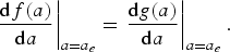 $$\left. {\displaystyle{{{\rm d}f\lpar a\rpar } \over {{\rm d}a}}} \right\vert _{a=a_{e} }=\left. {\displaystyle{{{\rm d}g\lpar a\rpar } \over {{\rm d}a}}} \right\vert _{a=a_{e}}.$$
The continuity of the derivatives ensures that the transition is smooth.
 $$ma_{e}^{2}+na_{e}^{4}=1 - qga_{e}^{2}+\lpar q - 1\rpar ga_{e}^{4} - c.$$
Calculating the derivatives from (5) and (7), and substituting them in (9):
 $$m+2na_{e}^{2}=- qg+2\lpar q - 1\rpar ga_{e}^{2}.$$
The parameters m and n can be easily solved from (10) and (11) to yield the following results:
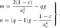 $$\left. \matrix{m=\displaystyle{{2\lpar 1 - c\rpar } \over {a_{e}^{2} }} - qg \hfill \cr n=\lpar q - 1\rpar g - \displaystyle{{1 - c} \over {a_{e}^{4} }} \hfill} \right\}.$$
The parameter a e can be calculated from the geometry using (4), the parameters q and g can be calculated from the feed horn characteristics, and the value of c can be approximated from the expected field reduction caused by the blockage. Thus, using (12), m and n can be calculated.
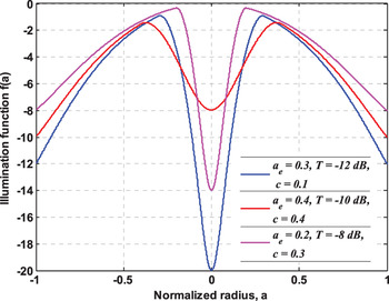
As all the parameters are defined and related to known quantities, the definition of the illumination function is complete. Figure 3 shows the plot of the defined illumination function for some arbitrary parameters. The q parameter does not significantly affect the shape of the illumination function. The value of q = 0.4 is used for numerical analysis in this paper.
Plot of the defined illumination function.

IV. AF INTEGRATION AND FAR-FIELD FORMULATION
The far-field radiation pattern can be calculated by performing the AF integration [Reference Munro, Whitaker and McInnes14]. An observation point P(r, θ, φ) in the far-field region is defined by its spherical coordinates (r, θ, φ). The point is shown in Fig. 1. For a circularly symmetric aperture distribution with constant phase, the far-field radiation pattern can be approximated by the following integral [Reference Baars4]:
 $$f\lpar \theta\comma \; \phi \rpar =\displaystyle{{\pi d_{p}^{2} } \over 2}\int\limits_{a=0}^{1} {A\lpar a\rpar J_{o} \left({\displaystyle{{kd} \over 2}a\sin \theta } \right)a\, {\rm d}a}.$$
Here, k =2π/λ=wave number, λ = wavelength and, Jp(·) = Bessel function of the first kind and order p. The angular coordinate variable, u is defined as:
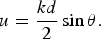 $$u=\displaystyle{{kd} \over 2}\sin \theta.$$
Using (14) and substituting the value of the illumination function from (3) in (13), the integral becomes:
 $$f\lpar \theta\comma \; \phi \rpar =\displaystyle{{\pi d_{p}^{2} } \over 2}\left[{\int\limits_{a=0}^{a_{e} } {g\left(a \right)J_{o} \lpar ua\rpar a\, {\rm d}a} } \;{+\int\limits_{a=a_{e} }^{1} {f\left(a \right)J_{o} \lpar ua\rpar a\, {\rm d}a} } \right].$$
The value of f(a) and g(a) can be substituted from (5) and (7). The resulting formulation involves integrating product of polynomials and Bessel function. The necessary integration results are [Reference Polyanin and Manzhirov15]:
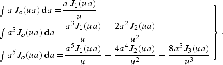 $$\left. \matrix{\int {a\, J_{o} \lpar ua\rpar \, {\rm d}a=} \displaystyle{{a\, J_{1} \lpar ua\rpar } \over u} \hfill \cr \int {a^{3} J_{o} \lpar ua\rpar \, {\rm d}a=} \displaystyle{{a^{3} J_{1} \lpar ua\rpar } \over u} - \displaystyle{{2a^{2} J_{2} \lpar ua\rpar } \over {u^{2} }} \hfill \cr \int {a^{5} J_{o} \lpar ua\rpar \, {\rm d}a=} \displaystyle{{a^{5} J_{1} \lpar ua\rpar } \over u} - \displaystyle{{4a^{4} J_{2} \lpar ua\rpar } \over {u^{2} }}+\displaystyle{{8a^{3} J_{3} \lpar ua\rpar } \over {u^{3} }} \hfill} \right\}.$$
To simplify the expressions, Bessel functions are replaced by Lambda function Λp(.) defined as [Reference Polyanin and Manzhirov15]:
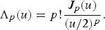 $$\Lambda _{p} \lpar u\rpar =p!\displaystyle{{J_{p} \lpar u\rpar } \over {\lpar u/{2}\rpar ^{p} }}.$$
After evaluating the integrals in (15) and normalizing the results, the obtained expression of normalized far-field radiation pattern, fN(θ, ϕ) is:
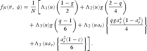 $$\eqalign{f_{N} \lpar \theta\comma \; \phi \rpar & =\displaystyle{1 \over N}\left[{\Lambda _{1} \lpar u\rpar \left({\displaystyle{{1 - g} \over 2}} \right)+\Lambda _{2} \lpar u\rpar g\left({\displaystyle{{2 - q} \over 4}} \right)} \right. \cr & \quad +\Lambda _{3} \lpar u\rpar g\left({\displaystyle{{q - 1} \over 6}} \right)+\Lambda _{2} \left({ua_e } \right)\left\{{\displaystyle{{qga_{e}^{4} \left({1 - a_{e}^{3} } \right)} \over 4}} \right\}\, \, \cr & \left. \quad {+\Lambda _{3} \left({ua_{e} } \right)\left\{{\displaystyle{{a_{e}^{2} \lpar 1 - c\rpar } \over 6}} \right\}} \right].}$$
Here, the normalizing factor, N is given by:
 $$N=\displaystyle{1 \over {12}}\left\{{6 - 2g - 2a_{e}^{2} \lpar 1 - b\rpar } \right.\left. {+\, qg\left({3a_{e}^{4} - 3a_{e}^{7} - 1} \right)} \right\}.$$
Equation (18) gives the approximate closed-form expression of the far-field radiation pattern of the Cassegrain antenna, which is expected to be sufficiently accurate near the main-lobe region of the antenna.
V. NUMERICAL RESULTS
For numerical analysis, a standard Cassegrain antenna with the main reflector diameter d p = 2 m, primary focal length f p = 0.8 m, subreflector diameter d s = 0.5029 m, and distance between subreflector foci 2c = 0.7 m is assumed. The relation between these parameters and other geometrical parameters are calculated using the method described in [Reference Granet13]. A typical edge taper of 10 dB is assumed, implying T = 10−10/20 = 0.3162. The parameter a e is found from (4) as 0.25145. The operating frequency is assumed to be 10 GHz. It is found that for the defined geometry and edge taper, q = 0.4 accurately describes a conical corrugated horn feed. The q parameter value is calculated using the method described in [Reference Zaman, Choudhury, Gaffar and Matin8].
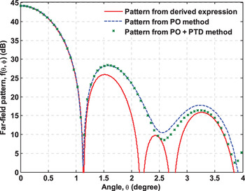
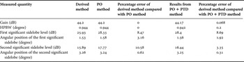
The far-field radiation pattern calculated using (18) and using the standard PO method [Reference McNamara, Pistorius and Malherbe5] is shown in Fig. 4. It can be seen from Fig 4 that the main-lobe patterns obtained from the two methods are exactly the same. The first few sidelobe levels obtained from the derived expression differ from the results of the PO method only by a few dB. The results are summarized in Table 1. It can be observed from the data that the gain and half-power beamwidth (HPBW) computed from the derived method are almost identical to the results obtained from the PO and PO + PTD methods, showing a maximum error of only 0.2% (accuracy of 99.8%). The proposed method has an error around 2–3% in identifying the angular position of the first sidelobe. The error in computing the first sidelobe level is around 8–9%. This implies that the prediction of the first sidelobe is up to 91% accurate. The proposed method also satisfactorily predicts the position and the amplitude level of the second significant level with errors as little as 0.3% and 3.35%, respectively, when compared with the PO + PTD method. This error is higher when compared with the PO method (without PTD correction). However, PO + PTD methods are expected to have more accuracy in sidelobe regions compared with the PO method. Thus, the derived equations also have excellent agreement in the second sidelobe region as well.
Far-field radiation pattern.

Comparison of numerical results obtained from the derived method, PO method, and PO + PTD method.

For a simplified closed-form expression, the accuracy of the derived equations can be considered satisfactory. The closed-form expression can be used for approximating the main-lobe and the first few sidelobes for cases where quick calculations are required. The PO method and PO + PTD method are computationally demanding and require significant simulation time for large reflectors [Reference McNamara, Pistorius and Malherbe5]. As the derived expression is closed form, the simulation time is drastically reduced.
VI. CONCLUSION
An illumination function for estimating the AF distribution is defined. The function takes into account the effect of subreflector blockage. Using the illumination function, the far-field radiation pattern is estimated by performing AF integration. A closed-form expression is obtained from the integration. The obtained results are compared with results from the PO method and the PO + PTD method, which are universally accepted as valid methods for reflector analysis. It is found that the results are in excellent agreement in the main-lobe region. As the radiation pattern of only the main-lobe region is often required, the derived method provides sufficient accuracy. Also, simulation time for the proposed method is much smaller compared with the PO method as the obtained results are closed-form.