I. INTRODUCTION
With many unique characteristics, such as low density, high specific strength, and good corrosion resistance, Ti can be used as high strength and lightweight structure materials for improving energy efficiency in airplane and automotive industries. Reference Munir, Kingshott and Wen1–Reference Zhang, Liao and Coddet3 Nevertheless, the relatively low hardness and resultant poor wear performance limit its wide application in load and abrasion environments. Reference Munir, Kingshott and Wen1 The addition of rare earth elements in Ti alloys has also restricted their use in industrial applications owing to the high-cost and shortage of resources. Therefore, the promising reinforcements are needed to fabricate Ti matrix composites (TMCs) to meet the growing demands in aerospace, automotive, and other engineering areas. The volume fraction, size, shape, and orientation of reinforcements in TMCs play a crucial role in determining the final mechanical properties. For particles reinforced TMCs, the micrometer scale ceramic particles, such as TiC, Reference Ye, Matsen and Dunand2 SiC, Reference Hall and Ritter4 TiB, Reference Attar, Bönisch, Calin, Zhang, Zhuravleva, Funk, Scudino, Yang and Eckert5 and TiN, Reference Balla, Bhat, Bose and Bandyopadhyay6 are commonly applied. Generally, the size of these particle reinforcements ranges from a few micrometers to several tens of micrometers. These relatively large-sized ceramic particles are normally difficult to be melted during processing due to the relatively high melting points. Accordingly, the interfacial bonding ability between ceramic reinforcing particles and metal matrix is limited because of the poor wettability between metals and ceramics. On the other hand, the densities and thermal expansion coefficients of ceramic particles and metal matrix are generally great deal of difference. Therefore, the cracks are normally generated during processing or mechanical loading, resulting in a premature failure of TMCs.
Carbon fibers are considered to be the innovative reinforcements for metal matrix composites. In particular, carbon nanotubes (CNTs) regarded as “ultimate fibers” have inspired great research interest since their discovery in 1991. Reference Lijima7 The nanoscale CNTs have been applied as promising reinforcements because of their extremely excellent mechanical property, superior thermal stability and good electrical property. Reference Bakshi, Lahiri and Agarwal8,Reference Woo, Hooper, Osswald, Bottolfson and Brewer9 Both theoretical and experimental researches reveal that CNTs have an excellent high strength of ∼100 GPa, high modulus of ∼1 TPa, and light weight of ∼2 g/cm3. Reference Treacy, Ebbesen and Gibson10,Reference Wong, Sheehan and Lieber11 The fiber reinforcements, such as CNTs, are testified to possess stronger strengthen effect than particle reinforcements due to the longer interreinforcement spacing. Combined with the superior properties of Ti and CNTs, CNTs/Ti composites are attractive to meet the increasing demands for high strength and lightweight structure materials. Many conventional methods, such as powder metallurgy, casting, and spraying, have been used to fabricate CNT reinforced metal matrix composites. Reference Bakshi, Lahiri and Agarwal8 Nevertheless, the high melting point and easily oxidability of Ti make it difficult to be fabricated by conventional methods, which are generally time-consuming due to the complicated postprocessing steps and difficult to build complex shapes. In addition, the nonuniform dispersion of CNTs in metal matrix is another great challenge for conventional methods due to their high van der Waals bonding force and high aspect ratio. Reference Choi, Shin, Min, Park and Bae12 As the extensive agglomeration is generated, the CNTs come into contact with each other rather than with Ti matrix, forming micropores, which have a greatly negative effect on the mechanical properties of the CNTs/Ti composites.
For overcoming the shortcomings of conventional methods, a new fabrication technique of direct metal laser sintering (DMLS) has been introduced for the fabricating of CNTs/Ti composites. As a typical rapid prototyping technology, DMLS is capable of rapid building three-dimensional components directly from loose metal powder according to user-defined CAD data with minimal or no postprocessing requirements. Reference Gu and Shen13 During DMLS process, the components are fabricated in a layer-by-layer manner by selective sintering of thin layers of loose powder using a mobile laser beam. Each scanned layer represents a two-dimensional cross-section of the object's mathematically sliced CAD model. After rapid consolidation of one powder layer, a fresh layer of powder is deposited and then the process is repeated until a component is built. Due to the flexibility in feedstock and shapes, DMLS accordingly offers a wide range of advantages, such as net-shape manufacturing, without using the expensive molds and high applicability for producing complex shaped parts that cannot be easily fabricated by conventional processing techniques. Nevertheless, DMLS fabricating CNTs/Ti composites has not been explored as far as author's knowledge and is considered to be an effective route. Due to the relatively low sintering temperature and significantly high heating/cooling rates of ∼103–108 K/s used during DMLS process, Reference Gu14 the nonequilibrium phases with fine-grained microstructure and unique mechanical properties can be produced. The starting materials of CNTs can improve the laser absorptivity, Reference Yuan and Huang15 which is beneficial to increase the energy utilization and improve the densification rate of the parts. Moreover, the presence of significant Marangoni flow and capillary force effect in laser molten pool Reference Gu and Shen16 will promote the uniform dispersion of CNTs in Ti matrix, resulting in the formation of excellent mechanical properties. However, the laser molten pool generally exhibits multiple modes of heat and mass transfer and complicated metallurgical processes, because of the high temperature gradients and rapid solidification nature of DMLS. These thus give rise to the uncontrollable development of microstructures during DMLS. DMLS processing parameters play a key role in determining the metallurgical features, microstructural evolution and resultant mechanical properties of final composite parts. Therefore, significant research and understanding are still required for the fabrication of novel CNT reinforced TMCs with controllable microstructures and properties.
In the present study, novel bulk-form CNTs/Ti composite components were built via DMLS. The densification level, microstructural characteristics, dispersion mechanism of CNTs, and the mechanical properties in terms of nanohardness and tribological performance were investigated.
II. EXPERIMENTAL
A. Powder preparation
The starting materials consisted of two components: 99.9% purity Ti powder with a spherical shape and a mean particle size of 25 μm served as the matrix material [Fig. 1(a)] and multi-wall CNTs with an average diameter of 9 nm and a mean length of 2 μm used as reinforcements [Fig. 1(b)]. The CNTs/Ti powder system containing 3 wt% CNTs was milled in a Pulverisette 4 vario-planetary ball mill (Fritsch GmbH, Idar-Oberstein, Germany), using a rotation speed of main disk of 300 rpm and a ball-to-powder weight ratio of 5:1. The milling time was set at 180 min with an interim period of 10 min for every 20 min milling to avoid over-heating. Such a pretreatment of CNTs-Ti powder system can promote the uniform dispersion of CNTs in powder system and improve the flowability of the composite powder, which is a key factor in favoring the powder deposition and the layer-by-layer shaping during DMLS.
Characteristic morphologies of (a) raw pure Ti powder and (b) CNTs.

B. DMLS processing
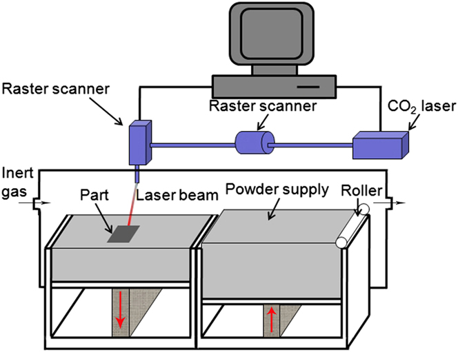
Figure 2 illustrates a schematic diagram of the DMLS apparatus used for laser sintering. The DMLS system was equipped with a continuous wave Gaussian CO2 laser, an automatic powder handling system, and a computer system for process control. Rectangular test specimens with dimensions of 10 × 10 × 5 mm3 were prepared. When specimens were to be built, a titanium substrate was fixed on the building platform and leveled. Then, a thin layer of milled loose powder with a thickness of 50 μm was layered on the substrate by a roller. Afterward, laser sintering was allowed to take place by a laser beam scanning over the powder bed surface to form a layer-wise profile according to the CAD data of the components. The similar process was repeated and the part was built in a layer-by-layer manner until completion. During DMLS process, the argon gas with an outlet pressure of 30 mbar was fed into the sealed building chamber, decreasing the oxygen content below 10 ppm. Laser processing conditions investigated were as follows: spot size of 70 μm, hatching spacing of 50 μm, laser power of 70 W, and scan speeds of 100, 200, 300 and 400 mm/s, respectively. Four different “linear laser energy densities” (η) of 175, 233, 350, and 700 J/m, which was defined by the ratio of laser power to scan speed, were used to integrally appraise the influence of the laser energy input per unit length on the densification response, distribution state of CNTs in Ti matrix and the materials properties of DMLS-processed CNTs/Ti composite parts.
Schematic diagram of the DMLS apparatus.

C. Microstructural and mechanical properties testing
The densification behaviors were revealed by using optical microscope (OM). The microstructures were analyzed by a Hitachi S-4800 field emission scanning election microscope (FE-SEM; Hitachi, Tokyo, Japan). The relative density of DMLS-processed specimens was determined based on the Archimedes principle. Nanoindentation tests on the polished bottom surfaces of DMLS parts were performed using a DUH-W201S nanoindentation tester (Shimazdu Corporation, Tokyo, Japan) at room temperature. A loading–unloading test mode was utilized with a maximum test force 100 mN, a loading speed 1.3239 mN/s and a hold time 10 s. In measurements, the load and indentation depth were recorded. The raw data were then used to construct loading–unloading plots. The hardness was defined as a ratio of the peak indentation load (F max) to the projected area of hardness impression (A c). According to Oliver–Pharr method, Reference Oliver and Pharr17 the dynamic nanohardness (H d) was calculated by:
 $${H_{\rm{d}}} = {{{F_{\max }}} \over {{A_{\rm{c}}}}} = {{{F_{\max }}} \over {26.43{h_{\rm{c}}}^2}}\quad ,$$
where h c is the contact depth under the maximum indentation load. The reduced elastic modulus (E r) was calculated from the unloading curve according to Reference Oliver and Pharr17 :
 $${E_{\rm{r}}} = {{\sqrt \pi } \over 2} \cdot {S \over {\sqrt {{A_{\rm{c}}}} }}\quad ,$$
where S was the slope of the unloading curve at the maximum displacement point.
Dry sliding wear tests on the DMLS parts were performed at room temperature using a CFT-I Fretting tribometer (Lanzhou ZhongKe KaiHua Sci. & Technol. Co., Ltd., Lanzhou, China). The bottom surfaces of DMLS specimens were ground and polished prior to wear tests. A Φ 3 mm bearing steel GCr15 ball was used as the counterface material and a test load of 4.2 N was applied. The drive shaft was rotated at 300 rpm for 15 min and the reciprocating sliding distance was fixed at 5 mm. The friction coefficients were recorded during sliding tests. The wear volume (V) was determined gravimetrically using V = M loss/ρ, where M loss was the weight loss of the DMLS parts after sliding tests and ρ was the density. The wear rate (ω) was evaluated by ω = V/(WL), where W was the contact load and L was the sliding distance.
III. RESULT AND DISCUSSION
A. Densification behavior
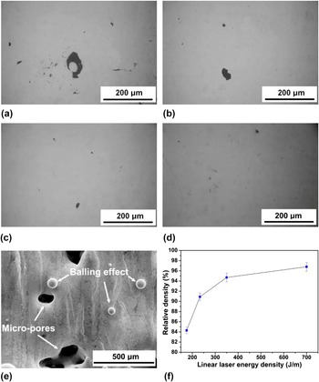
Figure 3 depicts the cross-sectional morphologies and relative density changes of DMLS-processed CNTs/Ti composite parts with the applied linear laser energy densities (η). When a relatively low η of 175 J/m was applied, the large-sized and irregular-shaped residual pores were formed on the cross-section of the DMLS part, leading to a limited densification rate merely of 84.3% [Figs. 3(a) and 3(f)]. FE-SEM characterization revealed that there were a number of metallic balls and interlayer pores generated on the DMLS-processed surface, as shown in Fig. 3(e). It indicated that the micro-pores and balling effect, which were typical metallurgical defect associated with powder bed based DMLS process, Reference Kruth, Levy, Klocke and Childs18,Reference Gu, Meiners, Wissenbach and Poprawe19 occurred on this occasion and restricted the densification level of the DMLS parts sharply. On increasing the applied η to 233 J/m by reducing the laser scan speed, the densification rate improved to 90.9% markedly [Fig. 3(f)]. The small-sized pores on the corresponding cross-section were dispersed and diminished [Fig. 3(b)]. The cross-section of the DMLS-processed part with an applied η of 350 J/m only consisted of a bit of micropores [Fig. 3(c)], which were significantly diminished, thereby improving the densification rate to 94.7% [Fig. 3(f)]. As η of 700 J/m was properly settled, sound cross-section morphology free of any apparent pores was obtained, hence achieving a dense part in near-full 96.8% density [Figs. 3(d) and 3(f)].
OM micrographs showing densification behaviors of DMLS-processed CNTs/Ti composite parts at various linear laser energy densities (η): (a) η = 175 J/m, (b) η = 233 J/m, (c) η = 350 J/m, and (d) η = 700 J/m. (e) Surface morphology of DMLS-processed part at a low η of 175 J/m showing the occurrence of balling effect and pores. (f) Variation of densification level of DMLS parts at different linear laser energy densities.

During DMLS, the CNTs/Ti composite powders are scanned in a line-by-line fashion by the laser beam, forming a mobile laser molten pool with a continuous liquid front. The amount of the melt formed in the pool has a significant effect on the densification and the resultant microstructure of the DMLS-processed parts by changing the thermo-kinetic and thermo-capillary characteristics such as wettability, viscosity and liquid–solid rheological properties. Due to the addition of CNTs in initial powder, the melt viscosity in the pool is significantly enhanced during laser processing, hence handicapping the sufficient flow of the melt and reducing the overall rheological performance of the pool. The dynamic viscosity μ of a molten pool is temperature-dependent and can be assessed by Reference Takamichi and Roderick20 :
 $$\mu = {{16} \over {15}}\sqrt {{m \over {kT}}} {\gamma _{{\rm{ls}}}}\quad ,$$
where m is the atomic mass, k the Boltzmann constant, T the operating temperature, and γls is the surface tension of liquid–solid interface. For the pure Ti liquid system, γls is dependent on the operating temperature (T, K) and can be estimated by Reference Mills and Su21 :
 $${\gamma _{{\rm{ls}}}} = 1670 - 0.16\left( {T - 1943} \right)\quad .$$
At a relatively low η, the dwell time of the laser beam on each irradiating region is relatively short and resultantly subdued operating temperature T of the pool. According to Eqs. (3) and (4), the higher dynamic viscosity was obtained in this instance. The influence of high dynamic viscosity reduced the wettability and hindered the Ti melt from spreading out smoothly. Then, the pores were formed as a consequence of the joint effect of poor flowability and rapid solidification rate, leading to an inferior densification behavior [Figs. 3(a) and 3(f)]. The balling effect connected with DMLS process was also responsible for the high surface roughness and limited densification level. According to previous studies, Reference Niu and Chang22 the instability of liquid track can be inhibited based on the premise of λ < πD, where λ is the laser wave length and D is the initial diameter of an unperturbed liquid cylinder. A higher scan speed and resultant lower laser energy input resulted in a rapid decrease of diameter D of the liquid cylinder at a constant laser wave length λ. Therefore, the localized instability of the melt flow enhanced and the instable liquid track tended to break up to several agglomerates in spherical shape so as to reduce the surface energy and achieve the final equilibrium state [Fig. 3(e)]. The balling effect enhanced the surface roughness of the DMLS-processed parts prominently. As a result, the uniform deposition of the fresh powder on the previously processed layer was destroyed during layer-by-layer DMLS process. As the laser beam scanned over such an uneven powder layer, especially at a high scan speed, the melting/solidification front of the moving molten pool generally suffered a significant disturbance and even interruption, which further increased the porosity between the uneven DMLS layers. Moreover, the high surface roughness can lead to next nondense layer, resulting in chains effect. It was pertinent to conclude that balling effect and porosity were the crucial factors in degrading densification rate of DMLS-processed CNTs/Ti composite parts. Reference Gu and Shen23 With the increment of applied η, both dynamic viscosity and balling phenomenon were weakened, resulting in a progressive increase in densification behavior of the DMLS-processed parts [Figs. 3(b) and 3(c)]. Consequently, as the η of 700 J/m was properly settled, the nearly full dense part with smooth cross-section free of any apparent pores [Fig. 3(d)] was built via DMLS.
B. Microstructural characteristics
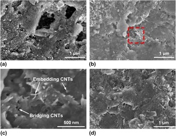
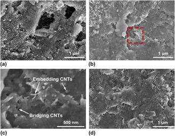
Typical microstructural characteristics on the surface of DMLS-processed CNTs/Ti composite parts at various linear laser energy densities (η) are depicted in Fig. 4. It was clear that the distribution state of CNT reinforcement in DMLS-processed composite parts with different laser energy inputs exhibited distinct variations. At a relatively low η of 175 J/m, the CNTs were curled, kinked, and tangled together because of the strong intertube van der Waals attraction, Reference Bakshi, Lahiri and Agarwal8 resulting in the formation of submicrometer-sized pores between CNTs clusters, as shown in Fig. 4(a). Accordingly, it was reasonable to conclude that the agglomeration of CNT reinforcement had an adverse impact on the densification behavior of the DMLS-processed composite parts. A closer examination revealed that the Ti matrix was scarcely immersed into the CNT clusters, which resulted mainly from the high dynamic viscosity of melt and resultant poor wetting property between CNTs and Ti. Reference Zhou and Hosson24 As the applied η increased to 350 J/m, the FE-SEM characterization revealed that the distribution state of CNT reinforcement was significantly improved. The homogeneous distribution of CNTs in Ti matrix was achieved and was free of any apparent micropores [Fig. 4(b)]. Nearly no CNT agglomerates could be found. High-magnification FE-SEM image revealed that the individual CNTs with obviously tubular structure were tightly embedded into Ti matrix. Some CNTs were bonding to the Ti matrix in a “bridging” manner, Reference Deng, Zhang, Wang, Lin and Li25 as depicted in Fig. 4(c). For the DMLS specimen at an applied η of 700 J/m, the surface was considerably dense and the CNTs were uniformly dispersed into Ti matrix [Fig. 4(d)]. It was thus pertinent to consider that the increase in applied η could promote the uniform dispersion of CNTs in Ti matrix.
SEM micrographs showing characteristic microstructures on the surfaces of the DMLS-processed CNTs/Ti composite parts at different linear laser energy densities (η): (a) η = 175 J/m, (b) η = 350 J/m, (c) partial enlarged detail of (b) showing typical morphologies of CNTs, and (d) η = 700 J/m.

As the mobile laser beam irradiates on the surface of predeposited powders, the temperature rise in any laser-irradiated region up to the melting point of Ti (∼1660 °C) is completed within an extremely short time (<4 ms), forming a so-called “sintering pool”. Reference Gu and Shen16 The large local temperature gradient and chemical concentration gradient developed in molten pool lead to the formation of surface tension gradient and associated Marangoni convection. Reference Niu and Chang26 The formation of such convective streams within the molten pool tends to generate liquid capillary force and resultant instability of melt flow. Reference Niu and Chang22 The liquid capillary induced by Marangoni convection generally exerts on the CNTs by the wetting liquid around and accelerates their rearrangement within the molten pool. The intensity of Marangoni flow can be evaluated using the dimensionless Marangoni number (M a): Reference Arafune and Hirata27
 $${M_{\rm{a}}} = {{\Delta \sigma L} \over {\mu {v_{\rm{k}}}}}\quad ,$$
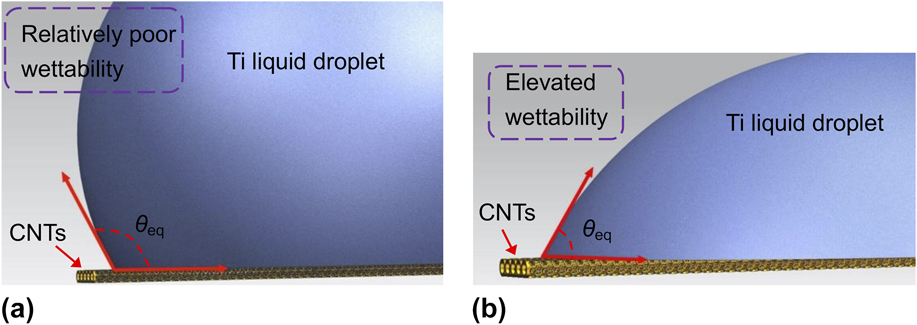
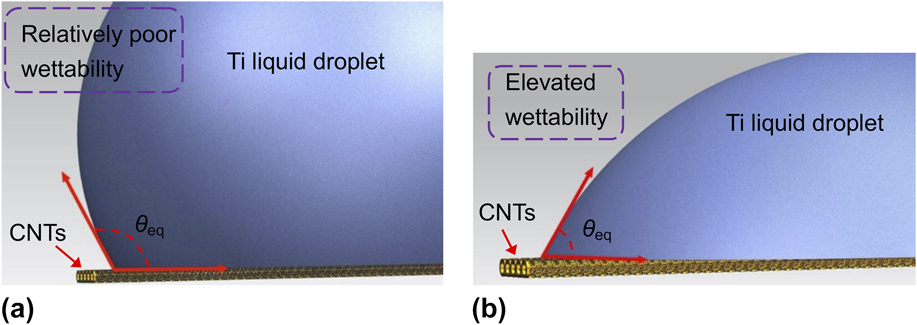
where the Δσ is the surface tension difference of Marangoni flow, L the length of the free surface, μ the dynamic viscosity, and v k is the kinematic viscosity. A proper increase in the applied η from 175 to 700 J/m tends to improve the operating temperature T. According to Eqs. (3)–(5), the dynamic viscosity μ was significantly decreased, thereby intensifying the Marangoni flow. Then stronger liquid capillary force is accordingly generated to accelerate the rearrangement of CNTs in the pool. On the other hand, the wetting of the CNT surface with melt liquid plays a key role in the DMLS processing. Wettability relates to the ability of a liquid to spread over a solid surface. For a liquid droplet on the CNT surface, the equilibrium contact angle θeq can be approximately expressed as Reference Gu, Meiners, Wissenbach and Poprawe19 :
 $$\cos {\theta _{{\rm{eq}}}} = {{\left( {{\gamma _{{\rm{sv}}}} - {\gamma _{{\rm{ls}}}}} \right)} \mathord{\left/ {\vphantom {{\left( {{\gamma _{{\rm{sv}}}} - {\gamma _{{\rm{ls}}}}} \right)} {{\gamma _{{\rm{lv}}}}}}} \right. \kern-\nulldelimiterspace} {{\gamma _{{\rm{lv}}}}}}\quad ,$$
where γsv, γls, and γlv are the surface tension of solid–vapor, solid–liquid, and liquid–vapor interfaces, respectively. On increasing the applied η, higher operating temperature T tends to reduce the surface tension of liquid–solid interface (γls) and resultant lower contact angle θeq, as illustrated in Fig. 5. Therefore, the wetting characteristics of CNTs by surrounding liquid are accordingly improved, favoring more Ti liquid to immerse into the CNT clusters and making a stronger interface bonding between CNTs and Ti matrix. Since the significant amount of Ti melt existed among CNTs at higher laser energy input, a unique repulsion force between CNTs reinforcement arises, Reference Anestiev and Froyen28 which can counteract the van der Waals attractive force and inhibit the agglomeration of CNTs. Combined with the super fast presence of liquid phase and the rapid consolidation of the pool, CNTs with an integral structure remain within Ti matrix in a uniform dispersion status.
The wetting characteristics of CNTs by the surrounding Ti liquid during DMLS: (a) relatively poor wettability at low laser energy input and (b) elevated wettability associated with enhanced laser energy input.
C. Nanoindentation and wear behavior
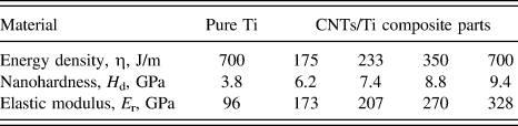
Figure 6 illustrates the nanoindentation load–depth curves measured on the polished bottom surfaces of DMLS-processed pure Ti and CNTs/Ti composite parts. The changes of nanohardness and elastic modulus are depicted in Table I. The indentation depth (∼1.0 μm) of pure Ti under the maximum load was considerably larger than that of the CNTs/Ti composite parts. According to Eqs. (1) and (2), the DMLS-processed CNTs/Ti composite parts, for all the given processing parameters, demonstrated superior H d and E r compared with the pure Ti part. Especially, when a reasonable η of 700 J/m was applied, the corresponding H d of 9.4 GPa and E r of 328 GPa of the CNTs/Ti composite part showed respectively ∼2.5- and ∼3.4-fold increase upon that of the unreinforced Ti part, which was prepared using the same processing conditions of the CNTs/Ti composite part (Table I). The higher nanohardness values of CNTs/Ti composite parts are attributed to the fact that CNTs have a higher stiffness than Ti matrix and their presence in Ti matrix can improve the hardness of the composites. A closer comparison revealed that the indentation depths of composite parts gradually decreased from 0.79 to 0.63 μm with the increase of the applied η. According to Eqs. (1) and (2), the H d and E r of the CNTs/Ti composite part processed at a proper η of 700 J/m showed a significant improvement in comparison with the composite part processed at a lower η of 175 J/m, which had a typical H d of 6.2 GPa and E r of 173 GPa (Table I). The relatively low nanohardness and elastic modulus of CNTs/Ti composite processed at an applied η of 175 J/m is ascribed to the presence of CNT clusters [Fig. 4(a)] and the poor densification level [Figs. 3(a), 3(e), and 3(f)]. In contrast, the uniform distribution of CNTs in Ti matrix combined with the high densification rate play a key role in further improving the dynamic nanohardness and elastic modulus. It is considered that the high aspect ratio and modulus of CNTs can produce high load transfer efficiently, and their uniform dispersion restrains the movement of lattice dislocations and the propagation of microcracks by absorbing more energy. Reference Liu, Yang, Wang, Qu, Li, Zhang, Li and Zhang29 In consequence, a remarkable increase in nanohardness and elastic modulus is achieved.
Loading–unloading curves of nanoindentation testing of DMLS-processed pure Ti and CNTs/Ti composite parts at various laser energy densities.

Nanohardness and elastic modulus of DMLS-processed pure Ti and CNTs/Ti composite parts.

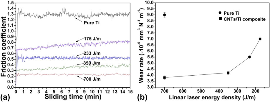
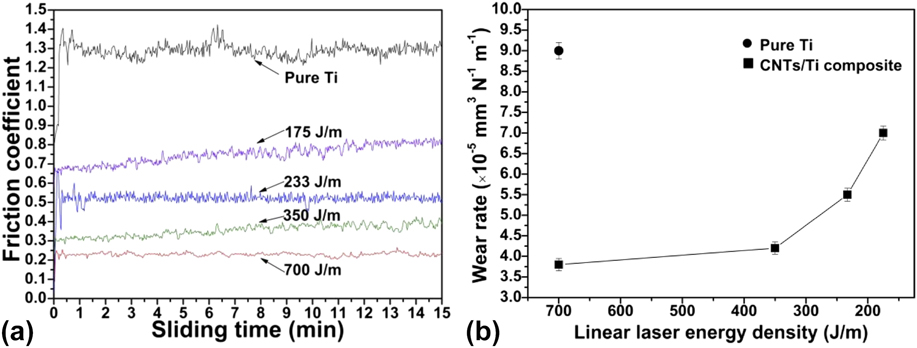
The variations of friction coefficients and wear rates as a function of linear laser energy density for the DMLS-processed pure Ti and CNTs/Ti composite parts are illustrated in Figs. 7(a) and 7(b), respectively. A comparative study revealed that all the CNTs/Ti composite parts generally possessed respectively much lower friction coefficients and wear rates than that of the pure Ti part, which had a mean friction coefficient value of 1.3 and a wear rate of 9.0 × 10⁻⁵ mm3/(N m) (Fig. 7). Also, the local fluctuation of the friction coefficients of the CNTs/Ti composite parts was considerably slighter compared with the unreinforced Ti part. The significantly improved wear performance of CNTs/Ti composite parts was thus ascertained. In addition, it was obvious that the applied η played a key role in determining the wear performance of CNTs/Ti composite parts. As a relatively low η of 175 J/m was applied, a considerably high friction coefficient value of 0.7 was produced, leading to an elevated wear rate of 7.0 × 10⁻⁵ mm3/(N m). As the applied η increased from 233 to 350 J/m, the average friction coefficients decreased from 0.52 to 0.33 and attendant wear rates from 5.5 × 10⁻⁵ to 4.2 × 10⁻⁵ mm3/(N m). The CNTs/Ti composite part fabricated at a proper η of 700 J/m exhibited the optimal wear performance. In this instance, a considerably low friction coefficient value of 0.23 was obtained, resulting in the lowest wear rate of 3.8 × 10⁻⁵ mm3/(N m).
Effect of linear laser energy density on (a) friction coefficient and (b) wear rate of the DMLS-processed pure Ti and CNTs/Ti composite parts.
To disclose the microstructural features accounting for the wear properties, the typical worn surfaces of the CNTs/Ti composite parts are characterized in Fig. 8. At a relatively low η of 175 J/m, the worn surface primarily consisted of parallel, deep grooves and a large amount of wear debris. At the start of sliding, the CNTs/Ti composite part and the hardened bearing steel ball contacted directly. As the sliding continued, the strong shear stress between the two mating metal surfaces generated wear debris and attendant the production of characteristic parallel abrasive grooves on the CNTs/Ti composites surface [Fig. 8(a)]. It was demonstrated that the main wear mechanism under this condition was abrasive wear. On increasing the applied η to 233 J/m, the amount of wear debris on the worn surface was reduced [Fig. 8(b)], indicating lesser material loss and resultant enhanced wear performance. For the DMLS specimen processed at an even higher η of 350 J/m, although shallow scratches were also visible on the worn surface, no apparent wear debris was existed [Fig. 8(c)]. A close examination revealed that the scars of plastic deformation by plowing were appeared on such a worn surface, which indicated that the adhesive wear mechanism was dominant in this situation. Such a wear mechanism was favorable for the improvement of wear resistance. Reference Li, Yuan, Qiu, Zhou and Li30 When an increased η of 700 J/m was settled properly, there was no any apparent grooves or wear debris that existed on the worn surface and the adherent tribolayer was formed as a result of the strain-hardening, Reference Guo, Zhou, Zhao, Wang, Yu, Chen and Zhou31 as illustrated in Fig. 8(d). The formation of such an adherent tribolayer is beneficial to decrease the friction coefficient value and keep a stable wear condition. High-magnification worn morphology at η of 175 J/m is shown in Fig. 8(e). The typical CNTs feature can be clearly visible on the worn surface.
SEM images showing typical morphologies of worn surfaces of DMLS-processed CNTs/Ti composite parts: (a) η = 175 J/m, (b) η = 233 J/m, (c) η = 350 J/m, and (d) η = 700 J/m. (e) The high-magnification image of (a) showing the presence of CNTs on the worn surface.

According to the above results, it is reasonable to conclude that the wear performance of TMCs has been improved by adding CNTs and is considerably influenced by the laser energy input. The mechanism of improvement is discussed along with the results as follows. First, it was considered that the enhanced hardness of CNTs/Ti composites played a crucial role in improving the wear performance. Reference Prashanth, Debalina, Wang, Gostion, Gebert, Calin, Kühn, Kamaraj, Scudino and Eckert32,Reference Cui, Lu, Wu, Liu and Gao33 The higher hardness could not only raise the stress for slip of materials, but also decrease the plow penetration. Therefore, the lower friction coefficient and resultant better wear resistance were obtained as a result of improved supporting capacity. Furthermore, the hardness of the CNTs/Ti composites enhanced with the increase in applied η, resulting in the gradually steady friction coefficient values and improved wear resistance. Secondly, the stable lubricating action of CNTs was another crucial factor to improve the wear performance of CNTs/Ti composites. Reference Qutub, Khalil, Saheb and Hakeem34,Reference Feng, Sui, Cai and Liu35 The CNTs in the composites could slowly release onto the metal surface during the sliding tests and serve as an excellent lubrication medium [Fig. 8(e)], preventing rough contact between the two mating metal surfaces, thereby lowering the friction coefficient considerably. Compared to the agglomeration of CNTs in TMCs fabricated at relatively low laser energy input, the wear resistance of the uniformly dispersed CNT reinforced TMCs was significantly improved, because of the homogeneous microstructural characteristics and superior metallurgical performance when a higher η was applied. Finally, the strain-hardened tribolayer was formed on the surface owing to sufficient plastic deformation, which was expected to stabilize the friction coefficient and reduce the wear rate. Reference Jia and Gu36 In consequence, the combined action of these three factors prevented the seizure of material phenomenon on the contact surface as well as improved the wear resistance. The enhanced wear resistance contributes to promoting the applications of TMCs in aerospace, industrial areas, and orthopedic implants.
IV. CONCLUSION
The present article reported on the densification level, distribution characteristics of CNTs and mechanical properties in terms of nanohardness and wear performance of DMLS-processed CNTs/Ti composite components. The main conclusions were drawn as follows:
-
(1) The applied linear laser energy density η played a crucial role in determining the densification behavior of the CNTs/Ti composite components. The densification level was restricted when a relatively lower η was applied, due to the occurrence of balling effect and micropores. A near-full 96.8% density was produced as an applied η of 700 J/m was properly settled.
-
(2) The typical microstructures of DMLS-processed CNTs/Ti composites experienced successive evolution. With the increase of laser energy input, the distribution states of CNTs in Ti matrix changed markedly from agglomeration to homodisperse. At a reasonable η of 700 J/m, the CNTs uniformly dispersed within the composite and the Ti matrix was significantly immersed among CNTs, owing to the effect of prominent Marangoni flow and superior flowability of Ti melt in laser molten pool.
-
(3) The DMLS-processed CNTs/Ti composite parts, for all the given processing parameters, demonstrated superior H d and E r in comparison with the pure Ti part. Especially, when a η of 700 J/m was applied, the H d and E r of the CNTs/Ti composite part showed, respectively, ∼2.5- and ∼3.4-fold increase upon that of the unreinforced Ti part. On decreasing the applied η, the dynamic nanohardness and elastic modulus gradually reduced for the composite parts, because of the presence of CNT clusters and the poor densification level.
-
(4) The wear resistance of CNTs/Ti composite parts processed at various laser energy inputs revealed a distinct improvement compared with pure Ti part. The wear performance of CNTs/Ti composites meliorated gradually on increasing the applied η. At an optimal η of 700 J/m, a considerably low friction coefficient of 0.23 and a reduced wear rate of 3.8 × 10⁻⁵ mm3/(N m) were achieved, which were attributed to the combined influence of elevated nanohardness, the self-lubrication action of uniformly dispersed CNTs and the formation of adherent tribolayer on worn surface.
ACKNOWLEDGMENTS
The authors gratefully acknowledge the financial support from the National Natural Science Foundation of China (Nos. 51322509 and 51575267), the Top-Notch Young Talents Program of China, the Outstanding Youth Foundation of Jiangsu Province of China (No. BK20130035), the Program for New Century Excellent Talents in University (No. NCET-13-0854), the Science and Technology Support Program (The Industrial Part), Jiangsu Provincial Department of Science and Technology of China (No. BE2014009-2), the 333 Project (No. BRA2015368), Science and Technology Foundation for Selected Overseas Chinese Scholar, Ministry of Human Resources and Social Security of China, the Aeronautical Science Foundation of China (No. 2015ZE52051), the Shanghai Aerospace Science and Technology Innovation Fund (No. SAST2015053), the Fundamental Research Funds for the Central Universities (Nos. NE2013103 and NP2015206), the Foundation of Graduate Innovation Center in NUAA and the Fundamental Research Funds for the Central Universities (No. kfjj20150601), and the Priority Academic Program Development of Jiangsu Higher Education Institutions.