1. Introduction
The study of flow behaviour near the free surfaces of the water holds significant importance in various underwater applications, including marine vehicles, underwater robots and emerging technologies such as floating wind turbines. The locomotion of marine vehicles, the navigation of underwater robots and the operational dynamics of floating wind turbines are all affected by their interaction with the free surfaces of the water. This interaction plays a key role in the performance and efficiency of such marine and offshore structures. To better understand these interactions, we investigate the fundamentals of the hydrodynamic interaction of fluid flow with a stationary, rigid flat plate at various angles of attack, with a particular emphasis on the role of flow-induced asymmetry. The hydrodynamic study of geometric asymmetry in structures interacting with surrounding fluid flow has been extensively explored, including asymmetric boundary conditions for the structure (Bourguet & Jacono Reference Bourguet and Jacono2014; Seyed-Aghazadeh et al. Reference Seyed-Aghazadeh, Edraki and Modarres-Sadeghi2019; Bourguet Reference Bourguet2021), variations in cross-sectional geometry (Mohebi et al. Reference Mohebi, du, Phillip, Robert and Wood2017; Jiang & Cheng Reference Jiang and Cheng2018; Ng et al. Reference Ng, Vo and Sheard2018; Jagad et al. Reference Jagad, Mohamed and Samtaney2020; Masoudi et al. Reference Masoudi, Sims-Williams and Gan2023) and variation in angles of attack (Yoon et al. Reference Yoon, Yang and Choi2010; Zhao et al. Reference Zhao, Leontini, Jacono and Sheridan2014; Seyed-Aghazadeh et al. Reference Seyed-Aghazadeh, Benner, Gjokollari and Modarres-Sadeghi2021). Still, the complexities introduced by flow-induced asymmetry near the free surface have not been thoroughly studied. In the current study, we focus on the influence of flow asymmetry resulting from the proximity of the plate to the free surface of the water. This influence is examined while systematically varying the Reynolds number (
 $Re = {\rho U c}/{\mu }$
, where
 $c$
denotes the chord length,
 $U$
the cross-flow velocity, and
 $\rho$
and
 $\mu$
represent the flow density and dynamic viscosity, respectively), angles of attack and submerged height. To introduce the asymmetric boundary conditions to the system, we reduce the distance between the flat plate and the free surface of the water, thus modifying the gap ratio between the two.
Flow past stationary flat plates is a classical yet complex fluid dynamics problem that has intrigued researchers and engineers for decades. The combination of various factors, including angles of attack and flow velocities, leads to a wide range of flow patterns and phenomena. One of the main features of the flow past a flat plate is the development of a boundary layer, subsequent shear layer instabilities, and separation from leading and trailing edges (Nakamura et al. Reference Nakamura, Ohya and Tsuruta1991). The pioneering research by Fage & Johansen (Reference Fage and Johansen1927) is one of the earliest investigations into vortex shedding from a flat plate submerged in a flow. The study investigated the fluid flow behaviour around the plate over various angles of attack, ranging from normal to almost parallel orientations. Their findings revealed that at the angle of attack of
 $\theta =90^\circ {}$
(when the plate was perpendicular to the incoming flow direction), the two shear layers exhibited equal strength, resulting in the shedding of a symmetric vortex street. However, the transition occurred at angles of attack of
 $\theta \lt 90^\circ {}$
, where the inclined plate induced a shift towards asymmetric vortex shedding. A highly asymmetric mean velocity vector field was observed behind the inclined flat plate in the experimental work conducted by Perry & Steiner (Reference Perry and Steiner1987) on the stationary flat plate. The study highlighted the shedding of leading and trailing-edge vortices (LEVs and TEVs) with unequal strengths, showing the uneven nature of the vortex shedding pattern over the inclined flat plate. Furthermore, Taira et al. (Reference Taira, Dickson, Colonius, Dickinson and Rowley2007) and Taira & Colonius (Reference Taira and Colonius2009) extensively examined several aspects of flow over the flat plate at a low Reynolds number of
 $Re=300$
, including flow separation, the interaction of leading and trailing edge vortices, flow unsteadiness, and the influence of inclination angle. Their results investigated the detachment of LEVs and TEVs from the plate and their complex interaction in the wake region. Unsteady shear layer separation and formation of the corresponding LEVs and TEVs were experimentally investigated by Mulleners & Raffel (Reference Mulleners and Raffel2012, Reference Mulleners and Raffel2013), Winslow et al. (Reference Winslow, Otsuka, Govindarajan and Chopra2018) and Zhang et al. (Reference Zhang, Hayostek, Amitay, He, Theofilis and Taira2020).
In our current study, we hypothesise that positioning the flat plate close to the free surface of the water may lead to the interaction of shed vortices with the deformable surface, giving rise to intricate vortex interaction phenomena. Our study aims to explore this hypothesis by conducting water tunnel experiments to understand the underlying dynamics. Previous research has demonstrated that when flow interacts with nearby inclined or curved surfaces, the Coanda effect can lead to flow reattachment to these surfaces (Bourque & Newman Reference Bourque and Newman1960; Sawyer Reference Sawyer1963; Kruka & Eskinazi Reference Kruka and Eskinazi1964; Neuendorf & Wygnanski Reference Neuendorf and Wygnanski1999; Pramanik & Das Reference Pramanik and Das2013; Skotnicka-Siepsiak Reference Skotnicka-Siepsiak2022). We hypothesise that a similar effect may occur with jet flow over an inclined flat plate, where proximity to the free surface could further constrain and direct the flow along the plate due to the Coanda effect. The Coanda effect, a fundamental phenomenon in fluid dynamics, occurs when a fluid jet adheres to a nearby curved or inclined surface rather than following its expected straight path (Ahmed Reference Ahmed2019). This effect arises from the interplay of viscosity, fluid momentum, confinement and surface curvature or inclination. As a fluid jet approaches such a surface, inertial forces push the fluid along its original trajectory, while adhesive forces cause it to adhere to the surface. This interaction can significantly alter the flow patterns around objects like inclined flat plates.
The interaction between vortices and the deformable free surface of water is a complex phenomenon observed in various natural and engineering contexts. This interaction has gained significant attention from researchers using both experimental and numerical approaches to understand the underlying physics of this phenomenon. Experimental investigations have employed various techniques to generate and visualise vortices near the free surface (Tyvand Reference Tyvand1990; Gharib & Weigand Reference Gharib and Weigand1996; Quyuan & Chu Reference Quyuan and Chu1997; Dabiri & Gharib Reference Dabiri and Gharib2001; Terrington et al. Reference Terrington, Hourigan and Thompson2022). These studies have investigated the influence of various parameters, including vortex strength, Froude number, Weber number, aspect ratio and angle of incidence, on both free surface deformation and vortex evolution. For instance, Barker & Crow (Reference Barker and Crow1977) examined the two-dimensional interaction of vortex pairs with both deformable and solid surfaces. They observed a ‘rebounding effect’, i.e. vortices turning away from the free surface at the point of closest proximity between the vortex and the surface. However, when the free surface was replaced with a no-slip solid plate, the fundamental dynamics of the vortices remained largely unchanged. The observed phenomena were attributed to the finite vortex core radius. This finite radius caused the circular core to deform into a non-circular shape during interaction with the free surface, resulting in dynamic changes in vortex shapes and vorticity distribution. Additionally, Sarpkaya & Henderson (Reference Sarpkaya and Henderson1985) showed the free surface deformation resulting from the shedding of TEV pairs behind a delta wing interacting with the free surface.
However, various numerical and experimental studies have investigated the interaction of vortices shed in the wake of bluff bodies, such as cylinders or spheres, with free surfaces (Sheridan et al. Reference Sheridan, Lin and Rockwell1995; Saelim Reference Saelim1999; Kawamura et al. Reference Kawamura, Mayer, Garapon and Sørensen2002; Reichl et al. Reference Reichl, Hourigan and Thompson2005; Chung Reference Chung2016; Sareen et al. Reference Sareen, Zhao, Sheridan, Hourigan and Thompson2018; Chizfahm et al. Reference Chizfahm, Joshi and Jaiman2021; Rajamuni et al. Reference Rajamuni, Hourigan and Thompson2021). Their findings reveal that the presence of a deformable free surface introduces asymmetric boundary conditions that significantly influence vortex shedding in the wake of these bluff bodies. For instance, in the study of an elastically mounted sphere, the presence of a free surface altered the behaviour of two symmetric trails of two-sided hairpin loops in the wake behind the sphere. The vortex loop near the free surface exhibited stretching, diffusion and tilting phenomena, leading to a moderately dense wake, characterised by small structures that displayed many interconnected loops rather than two distinct trails in the deeply submerged height (Rajamuni et al. Reference Rajamuni, Hourigan and Thompson2021). Reichl et al. (Reference Reichl, Hourigan and Thompson2005) demonstrated that the significant surface curvature resulting from the proximity of the circular cylinder to the free surface led to the generation of vortices with opposite signs of shedding from the upper surface. These secondary vortices diffused outward and were convected away from the surface, resulting in an asymmetric wake behind the structure. While previous studies have primarily examined the interaction of shed vortices from bluff bodies with free surfaces, the dynamics of streamlined structures near free surfaces remain relatively unexplored.
Few studies have addressed the interaction between the free surface and streamlined bodies such as flat plates and hydrofoils. Studies on the influence of free surface on streamlined structures have primarily focused on two-dimensional stability analysis, employing theoretical and computational techniques. For instance, research has examined both linear and nonlinear interactions between two-dimensional foils and free surfaces, highlighting the significant influence of the Froude number on the dynamics of the vortex-wave coupling (Giesing & Smith Reference Giesing and Smith1967; Salvesen Reference Salvesen1969; Plotkin Reference Plotkin1975; Yeung & Bouger Reference Yeung and Bouger1979; Kennell & Plotkin Reference Kennell and Plotkin1984; Tsai & Yue Reference Tsai and Yue1993). These studies also indicate that the presence of a free surface amplifies the vortex shedding frequency and alters the flow patterns, resulting in free surface deformation and the formation of vortices near the free surface (Grue et al. Reference Grue, Mo and Palm1988; Chen & Chwang Reference Chen and Chwang2002; Cleaver et al. Reference Cleaver, Calderon, Wang and Gursul2013). However, the influence of a solid surface on the fluid flow around streamlined structures has been explored in studies such as those by Molina et al. (Reference Molina, Zhang and Angland2011), Zhang et al. (Reference Zhang, Huang and Lu2017), Kurt et al. (Reference Kurt, Cochran-Carney, Zhong, Mivehchi, Quinn and Moored2019)and Zhong et al. (Reference Zhong, Han, Moored and Quinn2021). These investigations revealed the formation of shear layers on the solid surface due to the interaction of shed LEVs and TEVs with the surface. Consequently, these shear layers roll up and detach, interacting with vortices originating from the plate. In contrast, the ground effect does not involve a deformable surface that would induce the formation of surface vortices (Zhong et al. Reference Zhong, Han, Moored and Quinn2021). Instead, a shear layer forms and is subsequently displaced and lifted by shed vortices (Zhang et al. Reference Zhang, Huang and Lu2017; Kurt et al. Reference Kurt, Cochran-Carney, Zhong, Mivehchi, Quinn and Moored2019). In our recent study, we investigated the interaction between fluid, structure, and free surface dynamics for an oscillating flat plate with one and two degrees of freedom (Samsam-Khayani & Seyed-Aghazadeh Reference Samsam-Khayani and Seyed-Aghazadeh2024). Our findings revealed significant alterations in both structural and fluid responses near the free surface. The vortex dynamics of the flow near the free surface was notably disrupted, leading to the formation of elongated and fragmented vortices. Additionally, the flow dynamics of the system varied with the unsteady motion of the flat plate during different phases of the upstroke and downstroke motions near the free surface. Building upon this research, our current study focuses on investigating the interaction between vorticity generation resulting from the shedding of LEVs and TEVs from the flow past an inclined, stationary flat plate at various angles of attack with the free surface.
Despite the extensive research on the flow structure of flat plates and aerofoils, there appears to be a lack of experimental investigations focused on quantifying both asymmetric boundary and geometry conditions in stationary flat plates due to their proximity to the free surface and the inclination angle, respectively. To address this gap, our study aims to provide a comprehensive quantitative flow visualisation via a time-resolved two-dimensional particle image velocity (TR-2-D-PIV) technique. We will examine a wide range of angles of attack, ranging from
 $0^\circ {}$
to
 $35^\circ {}$
, along with Reynolds numbers within the range of
 $Re$
 $\approx$
 $10^3$
 $-$
3
 $\times$
 $10^4$
.
The structure of the paper is organised as follows. Section 2 presents a comprehensive overview of the experimental set-up and the methodology employed to measure the flow structure past the stationary flat plate. In § 3, we investigate the detailed findings, explaining the overall flow patterns observed across the entire range of tested flow velocities. Subsections 3.1 and 3.2 specifically focus on quantitative analyses of the wake structure under symmetric and asymmetric boundary conditions, respectively. Finally, § 4 summarises the key findings and implications of this research.
Schematic representation of the experimental apparatus set-up.

2. Experimental set-up and PIV measurement
Experiments were conducted in a re-circulating water tunnel that featured a test section with dimensions of 0.45 m
 $\times$
0.45 m
 $\times$
1.5 m. The turbulence intensity of the tunnel was less than 1 % at velocities up to
 $1\,\mathrm{m\,s}^{-1}$
. The flow in the tunnel is generated by a pump system that recirculates water through the test section, ensuring a continuous and stable flow environment. A rigid flat plate, fabricated from transparent acrylic, was used in these experiments. This plate had a chord length of
 $c = 101\,\mathrm{mm}$
and a span of
 $L = 303\,\mathrm{mm}$
, yielding an aspect ratio of
 $AR = L/c = 3$
. The thickness-to-chord ratio of the plate was
 $t/c=0.062$
, selected to ensure sufficient structural rigidity across the range of flow velocities tested. The ratios of chord length and span to the tunnel height and width are approximately 0.227 and 0.678, respectively, indicating that the wakes have ample space to evolve without significant confinement effects from the tunnel walls. In our previous work (Samsam-Khayani & Seyed-Aghazadeh Reference Samsam-Khayani and Seyed-Aghazadeh2024), we thoroughly analysed the wake structures, including the development of leading-edge vortices and trailing-edge vortices for a similar flat plate at various downstream locations. Our findings confirmed that these vortices exhibit a natural progression in both spatial and temporal evolution, validating the adequacy of the experimental set-up for capturing the wake dynamics accurately. The schematic of the experimental set-up is presented in figure 1. The system was designed to grant the plate various static angles of attack in the range of
 $\theta =0^\circ {-}35^\circ {}$
with increments of
 $5^\circ {}$
. The plate was hinged at the chord midpoint. The normalised submerged height,
 $H^*$
, was calculated as the ratio of the resting height,
 $H_o$
, to the thickness of the plate,
 $t$
. The resting height,
 $H_o$
, was obtained by measuring the distance from the water surface to the upper surface of the plate at
 $\theta =0^\circ {}$
, as shown in figure 1. This study covered a wide range of submerged heights for
 $H^*$
values from 15 to 5, representing symmetric and asymmetric boundary conditions, respectively.
Our definition of symmetric boundary conditions refers to scenarios where the plate is deeply submerged and the influence of the free surface on the flow field is negligible. Under these conditions, the flow remains largely unaffected by proximity-induced effects, resulting in a flow pattern that is essentially undisturbed by external boundaries. While not symmetric in a strict geometric sense, the flow field can be considered ‘unperturbed’ by the free surface. In contrast, asymmetric boundary conditions arise when the plate is positioned near the free surface. Here, the free surface acts as an asymmetric boundary condition, significantly altering the flow dynamics, particularly on the suction side of the plate. This asymmetry does not stem from the geometry of the plate, but rather from the imbalance introduced by the proximity of the free surface, which imposes additional constraints and modifies the flow-field structure.
In our experiments, the air remains quiescent and exerts no dynamic influence on the water flow. Consequently, the water flow maintains constant pressure and zero tangential stress conditions at the air–water interface. According to our earlier investigation, a submerged height of
 $H^*=15$
ensured that the deformable free surface had no impact on the flow dynamics surrounding the stationary flat plate, even when angles of attack varied (Samsam-Khayani & Seyed-Aghazadeh Reference Samsam-Khayani and Seyed-Aghazadeh2024). However, proximity to the free surface at a submerged height of
 $H^*=5$
allows for the influence of the deformable free surface on the flow dynamics around the flat plate, particularly evident during variations in angles of attack. During these tests, we kept the water level constant and gradually increased the flow velocity from 0 to
 $0.32\rm \,m\,s^-{^1}$
in small steps of
 $0.003\,\mathrm{m\,s}^{-1}$
, corresponding to the chord-based Reynolds number range of
 $Re_c=1030{-}32\,200$
.
Flow dynamics around the flat plate was quantitatively explored through the time-resolved two-dimensional particle image velocity (TR-2-D-PIV) (LaVision Inc., Ypsilanti, MI, USA) technique. The PIV system includes an Imager CX CMOS camera sensor with a resolution of 2048
 $\times$
2048 pixels. It captures PIV images with a maximum of 280 frames per second and is equipped with a
 $20$
mm lens. Additionally, a continuous laser is used to illuminate the seeding particles. The laser light sheet was generated using a 10 W continuous-wave laser beam operating at a wavelength of 532 nm. This beam was directed through cylindrical and spherical lenses to achieve the desired sheet configuration. The seeding particles were high-quality hollow glass polyamide spheres with a nominal diameter of 60
 $\unicode{x03BC}$
m. Multiple distinct subsets of 3000 images were acquired at each sample’s velocity. Figure 1 shows the schematic of the PIV measuring set-up, which includes the positions of the laser and camera. The total field of view is approximately [
 $x$
 $\times$
 $y$
] = 500 mm
 $\times$
150 mm which corresponds to 5
 $c$
 $\times$
1.5
 $c$
, where
 $c$
is the chord length of the plate. A final interrogation window of 32
 $\times$
32 pixels with 50 % overlap was used to satisfy the Nyquist criterion. Instantaneous and ensemble averaging of the flow velocity vectors was performed using a cross-correlation algorithm (Sciacchitano & Wieneke Reference Sciacchitano and Wieneke2016). The time-average of such quantities was obtained from 3000 frames of the instantaneous velocity field.
3. Results
In the following sections, the flow structure of the stationary flat plate at various angles of attack in the range of
 $\theta =0^\circ {-}35^\circ {}$
is investigated at two submerged heights of
 $H^*=15$
and
 $5$
. In our prior investigation of oscillating flat plates featuring one and two degrees of freedom (Samsam-Khayani & Seyed-Aghazadeh Reference Samsam-Khayani and Seyed-Aghazadeh2024), we observed that the behaviour of the system remained consistent at
 $H^*=15$
, seemingly indicating deep submersion, as the presence of the free surface had negligible impact. However, at
 $H^*=5$
, the free surface had a notable influence on the response of the system. Consequently, in our current analysis, we categorise the submerged heights of
 $H^*=15$
and
 $H^*=5$
as representing symmetric and asymmetric boundary conditions, respectively. At
 $H^*=15$
, the absence of influence from the deformable free surface on the flow dynamics around the stationary flat plate is guaranteed, even when there are varying angles of attack. Conversely, at
 $H^*=5$
, being close to the free surface, the influence of the deformable free surface on the flow dynamics around the stationary flat plate is particularly noticeable during changes in angles of attack.
Despite
 $H^*$
remaining constant, as it was measured at zero angles of attack, the distance between the leading edge of the flat plate and the free surface varies as the angle of attack changes. This distance between the free surface and the leading edge of the plate is represented by an additional dimensionless parameter,
 $y^*$
=
 ${y_h}/{c/2}$
, where
 $y_h$
is the distance between the leading edge of the plate and the free surface, and
 $c$
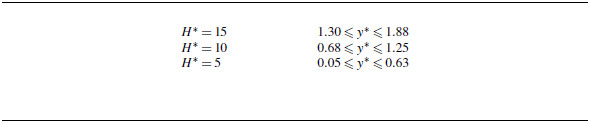
is the chord length of the plate. This parameter is introduced to enhance the generalisation of the dimensionless parameters presented in the current paper. Table 1 shows the variation of the dimensionless leading edge submerged height at various angles of attack for three tested
 $H^*$
. The leading edge submerged height, represented by
 $y^*$
, varies depending on the submersion depth,
 $H^*$
, and angles of attack,
 $\theta$
. The larger values of
 $y^*$
for deeply submerged cases, such as
 $H^*=15$
and
 $H^*=10$
, demonstrate a greater distance from the free surface and, consequently, less interaction with it. In contrast, the smaller values of
 $y^*$
for the near-free surface case of
 $H^*=5$
indicate increased interaction of the flow over the leading edge with the free surface. The results for the
 $H^*=10$
, corresponding to
 $0.68\leqslant y^*\leqslant {1.25}$
for the angles of attack range of
 $0^\circ {}\leqslant \theta \leqslant {35}^\circ {}$
, were found to be similar to those for
 $H^*=15$
,
 $1.30\leqslant y^*\leqslant {1.88}$
. These results are therefore excluded from the main text to avoid redundancy.
Leading edge submerged height for the range of
 $0^\circ {}\leqslant \theta \leqslant {35}^\circ {}$
.

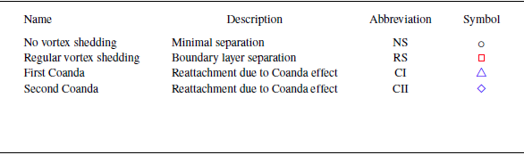
Our detailed analysis of PIV data revealed distinct flow regimes, which are subsequently mapped and schematically shown in figure 2. Table 2 shows the name, description, abbreviation and symbol for each flow pattern observed in the study. Based on the varying angles of attack and Reynolds number, we have categorised the hydrodynamics of the flow past the stationary flat plate into four distinct regimes at both submerged heights of
 $H^*=15$
and
 $5$
as:
-
(i) no vortex shedding (NS);
-
(ii) regular vortex shedding in the wake of angled streamlined bodies (RS);
-
(iii) reattached flow due to the Coanda effect near the free surface (first and second Coanda regimes – CI and CII); and
-
(iv) reversed flow regime (RF).
The following sections will provide a comprehensive discussion of the details of each category of the flow regimes. Figure 3 shows the schematic representation of the flow structures within various regimes shown in figure 2. As shown in figure 2, at an angle of
 $\theta =0^\circ {}$
, the flow past a flat plate exhibits similarity under both symmetric and asymmetric boundary conditions. This similarity holds whether the plate is deeply submerged or positioned near the free surface, where the influence of the free surface becomes negligible at this
 $\theta =0^\circ {}$
. In the flow map, we called this region ‘No vortex shedding’ (
 NS) (Eldredge & Jones Reference Eldredge and Jones2019). As shown in figure 3(a), flow past a flat plate at zero angles of attack typically results in a symmetric flow pattern with uniform velocity distribution along the plate surface. This flow configuration generates a boundary layer near the surface, and the absence of angles of attack minimises flow separation and leads to a relatively simple flow behaviour around the flat plate.
Descriptions of flow patterns.

Flow regime map showing the relationship between angle of attack (
 $\theta$
) and Reynolds number for (a) symmetric boundary condition (deeply submerged cases at
 $H^*=15$
) and (b) asymmetric boundary condition at
 $H^*=5$
. Symbols:
 NS represents the regime of no vortex shedding,
 RS represents the regime of regular shedding in the wake of streamlined bodies,
 CI and
 CII represent the regime of reattachment flow (Coanda phenomena), and
 RF represents the fully reversed flow.

Regular vortex shedding regime ( RS) was observed consistently across the entire range of Reynolds numbers tested at
 $\theta \geqslant 5^\circ {}$
for submerged height of
 $H^*=15$
, and
 $5^\circ {} \leqslant \theta \leqslant 30^\circ {}$
through a combination of Reynolds numbers for
 $H^*=5$
. At
 $H^*=15$
, with non-zero angles of attack and
 $H^*=5$
through the combination of
 $\theta$
and
 $Re$
, the interactions between fluid and plate cause deflection, separation, and vortex formation near the leading and trailing edges in what is named the ‘regular vortex shedding (RS)’ regime. As shown in figures 3(b) and 3(c), within this regime, the boundary layer undergoes complete separation from the plate surface, forming a large recirculation wake region behind the plate, whose thickness increases as the angle of attack increases. Within this wake region, various shedding vortices of differing sizes are shed from the leading and trailing edges of the plate. For
 $H^*=5$
within this regime, the interaction between the separated flow and the free surface led to surface deformation and the formation of corresponding free surface vortices, which will be discussed in § 3.2.
Schematic of the flow for various flow regimes: (a) no vortex shedding (NS); (b) regular vortex shedding (RS); (c) reattachment flow, Coanda phenomena (CI); (d) regular vortex shedding with deformed free surface near free surface (RS); (e) reattachment flow, Coanda phenomena (CII); and (f) reversed flow (RF). Red line represents created jet-like flow, blue dash-dotted line shows generated counter clockwise vortices, blue line represents TEV, black dash-dotted line shows clockwise vortex on the suction side, black inlinefig, shows reversed and entrained flow.

The first Coanda regime ( CI) was observed for
 $H^*=5$
, at
 $5^\circ {} \lt \theta \leqslant 25^\circ {}$
and low Reynolds values of
 $Re \leqslant 12\,500$
(but varied based on
 $\theta$
). The second Coanda regime (
 CII) was observed for
 $H^*=5$
, at
 $22\,360\lt Re \leqslant 32\,200$
and
 $5^\circ {} \leqslant \theta \leqslant 25^\circ {}$
. Within these two regimes, flow reattachment occurs due to the Coanda effect. The accompanying schematics illustrating the Coanda effect in both of these regimes are presented in figures 3(d) and 3(e) at low and high Reynolds numbers in the proximity of the free surface, respectively. The Coanda effect is a phenomenon in fluid dynamics where a fluid jet or stream adheres to a nearby curved or inclined surface rather than following its expected straight trajectory into the surrounding environment (Skotnicka-Siepsiak Reference Skotnicka-Siepsiak2022). This behaviour occurs due to the combined effects of viscosity, fluid momentum, confinement and the curvature or inclination of the surface. When a fluid jet encounters a curved or inclined surface, such as the surface of the angled flat plate (Sawyer Reference Sawyer1963; Kruka & Eskinazi Reference Kruka and Eskinazi1964; Neuendorf & Wygnanski Reference Neuendorf and Wygnanski1999; Skotnicka-Siepsiak Reference Skotnicka-Siepsiak2022), the fluid particles experience both inertial forces pushing them in their initial direction and adhesive forces that cause them to attach to the surface (Bourque & Newman Reference Bourque and Newman1960; Pramanik & Das Reference Pramanik and Das2013). In cases where the adhesive forces dominate due to the surface inclination and the fluid’s viscosity, the fluid stream follows the surface rather than detaching and defusing into the surrounding fluid. This effect can lead to a variety of outcomes, depending on factors such as the angle of the surface, the velocity of the fluid jet and the properties of the fluid itself. Generally, the Coanda effect can cause a jet to ‘stick’ to a surface, creating a flow pattern that wraps around the object.
As shown in figure 3(d), initially, within the first Coanda regime (CI) at
 $Re \leqslant 12\,500$
(but varied based on
 $\theta$
), the flow separates from the plate and interacts with the free surface. Owing to the comparatively low kinetic energy of the separated flow from the leading edge at these Reynolds numbers, the free surface remains relatively undeformed and the Coanda effect causes the flow to reattach to the surface of the plate, leading to the generation of jet-like flow and a separation bubble near the leading edge of the plate. The interaction between the created jet-like flow and entrained flow between the jet boundary and free surface causes the generation of a counterclockwise vortex (CCW), as shown in figure 3(d). At
 $22\,360\lt Re \leqslant 32\,200$
and
 $5^\circ {} \leqslant \theta \leqslant 25^\circ {}$
, the transition from regular shedding to the second Coanda regime (CII) occurs due to the large free surface deformation that drives the flow to reattach to the surface of the plate. However, due to the compression effect from the large surface deformation and Reynolds number, the separation bubble and thickness of the jet-like flow are smaller compared with the CI regime. Similar to the CI regime, the CCW vortex is generated due to the interaction between the jet boundary and entrained flow.
When the flat plate was positioned in proximity to the free surface with angles of attack exceeding
 $\theta \geqslant 25^\circ {}$
, a reversed flow condition (
 RF) was observed at these high angles of attack over a varied range of relatively high Reynolds numbers. This regime is characterised by a phenomenon where the gap between the leading edge of the flat plate and the adjacent free surface becomes notably small or, in some instances, non-existent. Within this particular flow regime, the fluid dynamics exhibit a reversal of flow patterns over the leading edge and alongside the counterclockwise TEV, as shown in figure 3(f). It should be noted that the newly identified Coanda and reversed flow regimes were not observed in the deeply submerged height scenario of
 $H^*=15$
. In the following sections, samples of PIV results will be shown at different angles of attack and Reynolds numbers for both submerged heights to provide a more detailed examination of the flow characteristics at different flow regimes identified.
3.1. Symmetric boundary condition
The initial series of experiments featured a rigid flat plate positioned at
 $H^*=15$
, maintaining a significant distance from the free surface. This configuration ensured that the deformable free surface had no impact on the flow dynamics around the stationary flat plate, even as it underwent variations in angles of attack. Initially set at
 $\theta =0^\circ {}$
, the angle of attack for the plate was incrementally increased up to
 $\theta =35^\circ {}$
. At each angle, the flow velocity was gradually increased to a maximum of
 $0.32\,\mathrm{m\,s}^{-1}$
. Throughout this section, we employ time-averaged streamwise velocity, vorticity, pressure, swirling strength (
 $\boldsymbol {\lambda _{\textit {ci},n}}$
) vector field and phase-averaged streamlines to discuss the detail of the flow dynamics surrounding the plate.
The time-averaged pressure field was calculated from velocity field PIV data employing the Reynolds-averaged Navier–Stokes (RANS) equation (Van Oudheusden Reference Van Oudheusden2013). Additionally, the lambda criterion for coherent structures (
 $\boldsymbol {\lambda }_{\textit {ci}}$
criterion) is a significant framework for identifying and characterising coherent vortices within complex flow fields. Central to this criterion is the concept of swirling strength (
 $\boldsymbol {\lambda }_{\textit {ci}}$
), a parameter that quantifies the rotational characteristics of fluid motion. Through the analysis of the eigenvalues of the velocity gradient tensor, the
 $\boldsymbol {\lambda }_{\textit {ci}}$
criterion detects regions of increased vortical activity, enabling a deeper understanding of flow dynamics. Higher values of
 $\boldsymbol {\lambda }_{\textit {ci}}$
are indicative of intensified vortical activity, highlighting the presence of coherent vortices. A vortical region is distinguished by a complex eigenvalue pair within the velocity gradient tensor, showing a swirling motion confined to a plane spanned by the respective eigenvectors (Zhou et al. Reference Zhou, Adrian, Balachandar and Kendall1999; Haller Reference Haller2005). As a consequence, the swirling strength (
 $\boldsymbol {\lambda }_{\textit {ci}}$
) could be defined based on the imaginary part of the eigenvalues of the velocity gradient tensor
 $\textbf {eig}(\boldsymbol {\nabla } \mathbf {u})$
for a given flow field (Zhou et al. Reference Zhou, Adrian, Balachandar and Kendall1999) as follows:
 \begin{align} \boldsymbol {\lambda }_{\textit {ci}}= \textrm{Im}(\textbf {eig}(\boldsymbol {\nabla } \mathbf {u}))= \textrm{Im} \left(\textbf {eig}\left [\begin{array}{cc} \dfrac {\partial {u}}{\partial {x}} & \dfrac {\partial {u}}{\partial {y}} \\ \dfrac {\partial {v}}{\partial {x}} & \dfrac {\partial {v}}{\partial {y}} \end{array}\right ] \right). \end{align}
Swirling strength is normalised (
 $\boldsymbol {\lambda _{\textit {ci},n}}$
) using the chord length,
 $c$
, and the free stream velocity
 $U_\infty$
as
 \begin{equation} \boldsymbol {\lambda _{\textit {ci},n}}= \frac {\boldsymbol {\lambda _{\textit {ci}}}\times c}{U_\infty }. \end{equation}
The phase-averaging technique was employed to provide a comprehensive understanding of the dynamic and unsteady behaviours of the fluid flows. It facilitated the analysis of transient phenomena and enabled the exploration of temporal interactions. The phase-averaging methodology used in this work builds on recent advancements where proper orthogonal decomposition (POD) is employed to extract periodic oscillations using the temporal coefficients of the most energetic POD modes, rather than relying on local velocity signals (Mohammadshahi et al. Reference Mohammadshahi, Samsam-Khayani, Nematollahi and Kim2020; Wen et al. Reference Wen, Li, Zhou, Yu, Muhammad, Liu and Wang2020a
; Wen et al. Reference Wen, Liu, Kim, Liu and Kim2020b
). This approach enhances robustness to turbulent fluctuations and ensures accurate phase identification for periodic flows, addressing limitations in earlier methods. This methodology involves capturing data at specific phases of the flow cycle, revealing temporal patterns and trends that are often hidden by instantaneous measurements alone. Velocity data obtained from instantaneous PIV snapshots serve as the basis for phase identification in this methodology. The snapshot POD method (Lumley Reference Lumley2007) was employed to obtain spatial and temporal modes of the velocity fluctuation. Subsequently, the phase angle of each snapshot was computed through the corresponding time coefficients of these POD modes via
 $\tan(\phi ) ^{-1} = {a_{1}(t)}/{a_{2}(t)}$
(where
 $a_1$
and
 $a_2$
are the temporal coefficients of the first and second POD modes). This calculation allowed for the precise determination of the phase angle associated with each snapshot. To establish the phase-averaged fields, the entire flow cycle was divided into 120 phase intervals, leading to capturing the temporal behaviour of the system. This subdivision ensured a thorough analysis across the complete range of the oscillation of the flow structures. As a result, a phase angle interval of
 $\pm 3^\circ {}$
was achieved, encompassing the full range of the variation of the flow.
When a flat plate is positioned in symmetric boundary conditions, where the influence of the free surface is negligible, and inclined relative to the incoming fluid flow, multiple phenomena emerge, influencing the flow behaviour. The flow dynamics over an inclined flat plate is influenced by various factors, including the angle of attack, Reynolds number, aspect ratio and thickness of the plate, as noted in previous studies (Taira et al. Reference Taira, Dickson, Colonius, Dickinson and Rowley2007; Taira & Colonius Reference Taira and Colonius2009). In the current study, we focus on angles of attack and Reynolds numbers for a plate with
 $AR = 3$
and a thickness-to-chord ratio of
 $t/c=0.062$
. These factors play an important role in determining the pressure difference between the upper and lower surfaces of the plate, as well as the onset and extent of the flow separation from the plate. In general, when flat plates are set at non-zero angles (
 $\theta \gt 0^\circ {}$
), as the flow encounters the plate, two shear layers develop at the leading and trailing edges, with unequal strength and size due to the geometric asymmetry condition (Nakamura et al. Reference Nakamura, Ohya and Tsuruta1991). Flow separation occurs at the leading edge corners, followed by fluid circulation in the clockwise direction, leading to a large recirculation region on the suction side of the plate. The current flat plate, featuring a thickness-to-chord ratio of
 $t/c=0.062$
, is characterised by high-pressure regions and increased separation tendencies, even at lower Reynolds numbers and angles of attack in the symmetric boundary condition (Nakamura et al. Reference Nakamura, Ohya and Tsuruta1991; Jin et al. Reference Jin, Ji, Liu and Chamorro2016; Francescangeli & Mulleners Reference Francescangeli and Mulleners2023). This high thickness of the flat plate results in increased pressure in front of the plate, consequently leading to a complete leading-edge separation of the flow from the suction side across all non-zero angles of attack and Reynolds numbers tested under symmetric boundary conditions.
Phase-averaged streamlines at
 $H^*=15$
for
 $Re=14\,160$
: (a–c)
 $\theta =15^\circ {}$
, and (d–f)
 $\theta =35^\circ {}$
.

Normalised time-averaged streamwise velocity (first column), pressure (second column), vorticity (third column), and swirling strength (fourth column) for
 $H^*=15$
and
 $\theta =15^\circ {}$
(
 $y^*=1.62$
) for various Reynolds numbers: (a–d)
 $Re=2670$
, (e–h)
 $Re=14\,160$
and (i–l)
 $Re=32\,200$
.

Normalised time-averaged streamwise velocity (first column), pressure (second column), vorticity (third column) and swirling strength (fourth column) for
 $H^*=15$
and
 $\theta =35^\circ {}$
(
 $y^*=1.30$
) for various Reynolds numbers: (a–d)
 $Re=2670$
, (e–h)
 $Re=14\,160$
and (i–l)
 $Re=32\,200$
. The PIV flow visualisation video at
 $Re=14\,160$
is also provided as supplementary movie 1).

In what follows, more details of the flow dynamics within the symmetric boundary condition at
 $H^*=15$
are discussed through three representative samples of Reynolds numbers (
 $Re=2670$
,
 $Re=14\,160$
and
 $Re=32\,200$
) at two specific angles of attack of
 $\theta =15^\circ {}$
(
 $y^*=1.62$
) and
 $\theta =35^\circ {}$
(
 $y^*=1.30$
). Figure 4 shows phase-averaged streamline plots at a moderate Reynolds number of
 $Re=14\,160$
, highlighting the unsteady flow dynamics within this symmetric boundary condition,
 $H^*=15$
, at both angles of attack of
 $\theta =15^\circ {}$
(see panels a–c) and
 $\theta =35^\circ {}$
(see panels d–f). The flow structures at three Reynolds numbers (
 $Re=2670$
in panels (a–d),
 $Re=14\,160$
in panels (e–h), and
 $Re=32\,200$
in panels (i–l)) at
 $H^*=15$
for both
 $\theta =15^\circ {}$
and
 $\theta =35^\circ {}$
are shown in figures 5 and 6. The visualisation includes normalised contours of time-averaged streamwise velocity in the first column, pressure in the second column, vorticity in the third column and swirling strength in the fourth column, all embedded with streamlines.
The phase-averaged plots of figure 4 show the characteristics of the flow at these two samples of angles of attack of
 $\theta =15^\circ {}$
(
 $y^*=1.62$
) and
 $35^\circ {}$
(
 $y^*=1.30$
) where the boundary layer was completely separated from the plate. As shown in figure 4, due to the velocity differences between the created shear layer from the leading edge, recirculation zone and cross-flow, separated shear layers underwent the Kelvin–Helmholtz (K-H) instabilities and were subsequently convected downstream of the flow, then merged, and created LEVs (figure 4
a–c). Figure 4 shows the alternating occurrence of vortex shedding at both the leading and trailing edges, resulting in the formation of a consistent vortex street within the wake. As shown in figure 4(b), the TEV begins to grow. Following the shedding of the TEV, the LEV starts to expand and is subsequently shed, driven by the conservation of vorticity. This repetitive cycle is presented in figures 4(b) and 4(c). As presented in the phase-averaged and time-averaged contours for the lower angle of attack of
 $\theta =15^\circ {}$
(figures 4–6), the shedding of unequal strength and size of LEV and TEV in the wake of the plate is observed, showing asymmetric wake patterns driven by the geometric asymmetric condition (inclined flat plate).
By increasing the angle of attack to
 $\theta =35^\circ {}$
, the wake thickness is increased compared with
 $\theta =15^\circ {}$
, as shown in figures 4(a) and 4(d). The shedding process of TEV and LEV, as described earlier, similarly repeats itself. Moreover, increasing
 $\theta$
causes the TEV and LEV to increase in size, and subsequently, the shedding for this high
 $\theta$
is dominated by both the LEV and TEV, as shown in both time-averaged and phase-averaged contours in figures 5, 6 and 4. Time-averaged vorticity and
 $\boldsymbol {\lambda _{\textit {ci},n}}$
criterion show the formation of shed vortices that exhibit less eccentricity, in contrast to the evolving vortical structures observed at lower angles of attack. Figure 4 shows that the shedding of the TEV initiates an extended series of positive (counterclockwise) vortices, which subsequently merge and interact with the LEVs and their corresponding TEVs. The backflow associated with the TEV migrates towards the leading edge of the suction side of the plate, causing the detachment of the LEVs from the plate shown in figure 4(e). This detachment causes the appearance of a stream of negative K-H vortices which are convected and merged downstream of the plate, as shown in the phase-averaged plots in figure 4(e). LEVs and TEVs experience a progressive loss of coherence and decrease in strength as they are convected downstream due to a combination of advection and diffusion processes. As the Reynolds number increases, it leads to the expansion of the wake region (thickness of wake increases), characterised by the core-reduced pressure, as shown in time-averaged pressure contours in figures 5(b), 5(f) and 5(j). Moreover, the strength and size of the positive and negative shear layers over the leading and trailing edges and LEVs and TEVs are increased as the Reynolds number increases, as shown in vorticity contours of figures 5 and 6(c), 6(g) and 6(k).
Additionally, as
 $\boldsymbol {\lambda _{\textit {ci},n}}$
criterion contours show, an increase in Reynolds number led to an increase in the strength of the separated shear layers at both leading and trailing edges, alongside the swirling region. This increase is evidenced by the larger positive core regions of both LEV and TEV. In summary, while a detailed examination of flow dynamics across various angles of attack and Reynolds numbers for
 $H^*=15$
was provided, it is important to note that all observed phenomena, including the shedding of LEV and TEV, along with their interactions, consistently occur within the regular vortex shedding (RS) region of the flow map. This indicates that the flow behaviour remains within the expected range of vortex-shedding regimes, as highlighted by the flow map analysis shown in figure 2. The PIV flow visualisation video for
 $\theta =35^\circ {}$
(
 $y^*=1.30$
) at
 $Re=14\,160$
is provided as supplementary movie 1 available at https://doi.org/10.1017/jfm.2025.270.
3.2. Asymmetric boundary condition
This section examines the flow dynamics surrounding the plate for the submerged height of
 $H^* = 5$
. Positioned near the free surface at
 $H^*=5$
, together with the asymmetric geometric configuration characterised by a non-zero angle of attack (corresponding to the variation of the leading edge submerged height), leads to substantial changes in the flow dynamics over and in the wake of the flat plate across various Reynolds numbers. These changes contrast with the flow dynamics observed at
 $H^*=15$
, as discussed in § 3.1. To better characterise the changes in flow dynamics under these conditions (
 $H^*=5$
), we first examine the results at
 $\theta =0^\circ {}$
(
 $y^*=0.63$
), as shown in figure 7. Following this, we study the effect of Reynolds number at a fixed angle of attack of
 $\theta = 15^\circ {}$
(
 $y^*=0.37$
), as shown in figures 8–15. Subsequently, the influence of angles of attack and Reynolds number is examined and analysed in figures 16–18.
Figure 7 shows non-dimensional time-averaged contours of the pressure, vorticity and swirling strength (
 $\boldsymbol {\lambda _{\textit {ci},n}}$
) for two Reynolds numbers of
 $Re=5950$
and
 $Re=32\,200$
, at
 $\theta =0^\circ {}$
and
 $H^*=5$
. At
 $\theta =0^\circ {}$
, the flat plate is aligned parallel to the incoming fluid flow, causing the relative motion between the fluid and the plate to be small. Under these conditions, the flow field exhibits characteristics similar to those of classical two-dimensional steady-state flow. A region of high pressure (shown in figures 7
a and 7
d) is generated near the leading edge of the plate due to the deceleration of the fluid at the stagnation point. This pressure distribution results in the initiation of boundary layer development along the surface of the plate. Viscous effects primarily govern the growth of the boundary layer and, at this particular angle of attack, the boundary layer thickness remains relatively small compared with scenarios with non-zero angles of attack (shown in figure 7
b). At higher
 $Re=32\,200$
, the pressure is increased at the stagnation point and leads to a relatively larger separation region at both sides of the plate, as shown by
 $\omega ^+$
and
 $\omega ^-$
vorticity and corresponding low-pressure regions in figures 7(b) and 7(e). Nevertheless, boundary layer separation remains minimal and the flow smoothly follows the contour of the surface of the plate, preserving attachment. Subsequently, the general instability is attributed to the K-H mechanism. This instability causes a sequence of small, alternating vortices that are rapidly shed from the trailing edge of the plate shown in figures 7(c) and 7(f) by the time-averaged
 $\boldsymbol {\lambda _{\textit {ci},n}}$
criterion contours. Therefore, the free surface does not significantly affect the flow dynamics at
 $\theta =0^\circ {}$
and within the tested Reynolds number range.
Normalised pressure (first column), vorticity (second column) and swirling strength (third column) for
 $H^*=5$
and
 $\theta =0^\circ {}$
for two Reynolds numbers: (a–c)
 $Re=5950$
and (d–f)
 $32\,200$
.

Normalised time-averaged streamwise velocity (first row), pressure (second row), vorticity (third row) and swirling strength (fourth row) for CI regime at
 $H^*=5$
and
 $\theta =15^\circ {}$
(
 $y^*=0.37$
) for three Reynolds numbers: (a–d)
 $Re=2670$
; (e–h)
 $Re=4310$
; (i–l)
 $Re=5950$
. The PIV flow visualisation video at
 $Re=5\,950$
is also provided as supplementary movie 2).

Normalised time-averaged streamwise velocity (first row), pressure (second row), vorticity (third row) and swirling strength (fourth row) for RS regime at
 $H^*=5$
and
 $\theta =15^\circ {}$
(
 $y^*=0.37$
) for three Reynolds numbers: (a–d)
 $Re=12\,510$
; (e–h)
 $Re=19\,080$
; (i–l)
 $Re=22\,360$
. The PIV flow visualisation video at
 $Re=22\,360$
is also provided as supplementary movie 3.

Normalised time-averaged streamwise velocity (first row), pressure (second row), vorticity (third row) and swirling strength (fourth row) for CII regime at
 $H^*=5$
and
 $\theta =15^\circ {}$
(
 $y^*=0.37$
) for three Reynolds numbers: (a–d)
 $Re=25\,640$
; (e–h)
 $Re=28\,920$
; (i–l)
 $Re=32\,200$
. The PIV flow visualisation video at
 $Re=32\,200$
is also provided as supplementary movie 4.

Phase-averaged streamline for
 $H^*=5$
and
 $\theta =15^\circ {}$
at three Reynolds numbers: (a–c)
 $Re=5950$
; (d–f)
 $Re=22\,360$
; (g–i)
 $Re=32\,200$
.

Normalised time-averaged Reynolds stresses (
 $\overline {u'u'}/{U_{\infty }^2}$
in the first column and
 $\overline {v'v'}/{U_{\infty }^2}$
in the second column) for
 $H^*=5$
and
 $\theta =15^\circ {}$
at three Reynolds numbers: (a and b)
 $Re=5950$
; (c and d)
 $Re=22\,360$
; (d and f)
 $Re=32\,200$
.

Obtained free surface profile for
 $H^*=5$
at
 $\theta =15^\circ {}$
for three flow regimes: CI regime at
 $Re=5950$
, RS regime at
 $Re=22\,360$
and CII regime at
 $Re=32\,200$
.

Circulation for two submerged heights of
 $H^*=15$
and
 $H^*=5$
at angle of attack of
 $\theta =15^\circ {}$
(
 $y^*=0.37$
) for the tested Reynolds number range of
 $Re=1000{-}32\,200$
.

Calculated wake thickness for (a) RS regime at
 $Re=19\,080$
for both submerged heights of
 $H^*=15$
and
 $H^*=5$
at various angles of attack in the range of
 $\theta =5^\circ {-} 35^\circ {}$
and (b)
 $H^*=5$
at
 $\theta =15^\circ {}$
(
 $y^*=0.37$
) at RS regime for various Reynolds numbers.

Normalised time-averaged streamwise velocity (first row), pressure (second row), vorticity (third row) and swirling strength (fourth row) for
 $H^*=5$
at
 $Re=5950$
for three selected angles of attack of (a–d)
 $\theta =5^\circ {}$
(
 $y^*=0.54$
), (e–h)
 $\theta =20^\circ {}$
(
 $y^*=0.20$
), (i–j)
 $\theta =35^\circ {}$
(
 $y^*=0.05$
).

Normalised time-averaged streamwise velocity (first row), pressure (second row), vorticity (third row), and swirling strength (fourth row) for
 $H^*=5$
at
 $Re=19,080$
for three selected angles of attack of (a–d)
 $\theta =5^\circ {}$
(
 $y^*=0.54$
), (e–h)
 $\theta =20^\circ {}$
(
 $y^*=0.20$
), (i–j)
 $\theta =35^\circ {}$
(
 $y^*=0.05$
). The PIV flow visualisation video for
 $\theta =35^\circ {}$
(
 $y^*=0.05$
) at
 $Re=19,080$
is provided as supplementary movie 5.

Normalised time-averaged streamwise velocity (first row), pressure (second row), vorticity (third row) and swirling strength (fourth row) for
 $H^*=5$
at
 $Re=32,200$
for three selected angles of attack of (a–d)
 $\theta =5^\circ {}$
(
 $y^*=0.54$
), (e–h)
 $\theta =20^\circ {}$
(
 $y^*=0.20$
), (i–j)
 $\theta =35^\circ {}$
(
 $y^*=0.05$
).

3.2.1. Effect of Reynolds number at a sample angle of attack of
 $\theta =15^\circ {}$
(
$y^*=0.37$
)


As shown in figures 2(c)–2(f) for the near free surface scenario, at the tested Reynolds number and the angle of attack of
 $\theta =15^\circ {}$
(
 $y^*=0.37$
), the flow structure is categorised into three distinct regimes: the first Coanda regime CI,
 $Re \leqslant 5950$
; the regular vortex shedding regime RS,
 $5950 \lt Re \leqslant 22\,360$
; and the second Coanda regime caused by the substantial deformation of the free surface CII,
 $22\,360 \lt Re \leqslant 32\,200$
. Figures 8–10 show time-averaged streamwise velocity (first row), pressure (second row), vorticity (third row) and swirling strength (fourth row) embedded with streamlines. These visualisations are presented for
 $\theta =15^\circ {}$
across a wide range of Reynolds numbers, spanning from 2670to 32 200. The purpose is to show the transition between various flow regimes as the Reynolds number changes. Additionally, figure 11 shows phase-averaged plots for
 $H^*=5$
at
 $\theta =15^\circ {}$
. We examine three samples of Reynolds numbers:
 $Re=5950$
(panels a–c),
 $Re=22\,360$
(panels d–f) and
 $Re=32\,200$
(g–i). These phase-averaged plots allow for a more detailed analysis of the unsteady characteristics of the flow, particularly within the first and second Coanda and regular vortex shedding regimes.
The first Coanda regime CI flow structures, presented in figure 8 through time-averaged contours, correspond to three samples of Reynolds numbers of
 $Re$
= 2670, 4310 and 5950. These structures arise from intricate flow interactions with the stationary plate. The separated shear layer impacts the free surface, leading to a phenomenon similar to rebounding or ’bouncing’ (Barker & Crow Reference Barker and Crow1977). Subsequently, the Coanda effect leads to the reattachment of the rebounded flow from the free surface to the suction side of the plate. This intricate process leads to a distinctive jet-like flow pattern. This jet phenomenon has also been reported in experimental and numerical studies of oscillation cylinders close to the free surface (Sheridan et al. Reference Sheridan, Lin and Rockwell1997; Carberry et al. Reference Carberry, Sheridan and Rockwell2004; Reichl et al. Reference Reichl, Hourigan and Thompson2005).
It is important to note that this flow pattern significantly contrasts with the conventional shedding observed in symmetric boundary conditions, as shown in figures 5(a)–5(d). In the low-Reynolds-number range of
 $Re \leqslant 5950$
, we observed that the vortical structures, or shed LEVs, are rebounded and modified by the free surface and the diffusion of vorticity occurs as the motion of the primary vortex is constrained by the free surface. In this flow regime, the free surface acts like a rigid plane, inducing velocities that propel the vortex while undergoing minimal deformation due to the high viscous forces. This phenomenon aligns with the study of the vortex interaction with a free surface, which highlights the role of the free surface in modulating vortex motion and maintaining the flow structure with negligible surface disruption (Rood Reference Rood1994a
,
Reference Roodb
).
Analysis of the time-averaged pressure contours (figures 8
b, 8
f and 8
j) reveals several significant flow characteristics. As the flow interacts with the plate, it undergoes bending towards the surface of the plate. The bending results in the formation of a localised recirculating region between the generated jet-like flow and the free surface. This region is characterised by a reduced pressure area, indicating a suction effect downstream of the plate, along with the reduced pressure area resulting from the presence of a laminar separation bubble (LSB) and the subsequent reattachment of the flow to the plate. Additionally, between the jet and the free surface, flow entrainment occurs, as shown by backflow or reversed flow streamlines, which serve to satisfy the entrainment requirements of the shear mixing layer. This process is associated with the formation of a large-scale recirculation area (counterclockwise vortex), observed downstream in the time-averaged vorticity contours of figures 8(c), 8(g) and 8(k). The velocity magnitude of the jet is notably substantial, approximately matching the order of magnitude of the cross-flow velocity of the approaching flow. This is shown in the streamwise velocity contours of figures 8(a), 8(e) and 8(i). Traditionally, in nozzle flow studies, the primary sources of vorticity on either side of a jet stem from solid surfaces, typically corresponding to the interior of the jet nozzle (Dabiri & Gharib 2005). However, within this CI regime, a configuration arises, featuring the formation of two positive and negative shear mixing layers on both sides of the jet flow. The positive shear layer,
 $\omega ^+$
, originates from the free surface, while the negative shear layer,
 $\omega ^-$
, starts from the leading edge of the plate, as shown in figures 8(c), 8(g) and 8(k). This characteristic justifies the use of the term ‘jet-like flow’ to describe this reattachment flow.
The influence of the Coanda is increased by increasing Reynolds numbers. Higher Reynolds numbers correspond to the greater prevalence of inertia relative to viscous forces, stimulating a stronger tendency for the fluid to adhere to the inclined surface. Consequently, this adherence propels the vortex core of the reversed flow between the positive mixing layer and the free surface from downstream to the leading edge shown by vorticity contours and embedded streamline in figures 8(c), 8(g) and 8(k). This phenomenon leads to a reduction in the thickness of the jet-like flow compared with at the lower Reynolds number, as shown in the streamwise velocity contours of figures 8(a), 8(e) and 8(i). Additionally, as the Reynolds number increases, the size of the LSB decreases, accompanied by the shifting of the separation point from the trailing edge to the leading edge, as evidenced by the streamwise velocity contours. This behaviour shows similar trends as those observed in the laminar flow regime of symmetric flows around plates with smaller thickness-to-chord ratios than the present flat plate (Winslow et al. Reference Winslow, Otsuka, Govindarajan and Chopra2018). With a thickness-to-chord ratio of
 $t/c=0.062$
, the current flat plate exhibits high-pressure regions and increased separation tendencies, even at lower Reynolds numbers and angles of attack in the symmetric boundary condition. This high thickness of the flat plate increases the pressure in front of the plate (shown in figures 8
b, 8
f and 8
j), leading to a nearly complete separation of the flow from the upper surface at non-zero angles of attack. The PIV flow visualisation video for
 $\theta =15^\circ {}$
(
 $y^*=0.37$
) at
 $Re=5\,950$
is provided as supplementary movie 2.
The transition from the CI (the first Coanda regime) to the RS (regular shedding) regimes is characterised by an increase in the Reynolds number (
 $5950 \lt Re \leqslant 22\,360$
), resulting in instability and detachment of the flow from the upper surface of the plate. This transition is driven by the increased kinetic energy or momentum of the cross-flow occurring between the leading edge and the free surface, which overcomes the Coanda effect. Consequently, the flow detaches from the surface of the plate, leading to the shedding of shear layers and the formation of LEVs. Time-averaged contours of the RS regime are shown in figure 9 for three Reynolds numbers. In this regime, the flow structure closely resembles regular shedding observed in symmetric boundary conditions, which is characterised by the unequal size and strength of LEVs and TEVs, as presented in figure 9. Due to the confinement effect, the streamwise velocity exhibits an increase in the gap between the leading edge of the plate and the free surface, as shown in figures 9(a), 9(e) and 9(j). As previously discussed in § 3.1, increasing the Reynolds number corresponds to increasing the strength of the LEV and TEV, as illustrated by time-averaged vorticity contours and embedded streamlines (figures 9
c, 9
g and 9
k). It is worth noting that in our experiments, the air remains quiescent and exerts no dynamic influence on the evaluation of water flow; hence, the water flow maintains constant pressure and zero tangential stress conditions at the air–water interface. As a result, the free surface deforms in response to the primary vortex field underneath, represented by shed LEVs, to maintain the conditions of zero tangential stress and constant normal stress at all times. Moreover, surface deformation significantly affects the wake flow structure and leads to the generation and flux of secondary vortices, commonly referred to as surface vortices (Green Reference Green1995). These deformations also generate capillary waves on the free surface.
As the Reynolds number increases, the free surface undergoes slight deformation, resulting in the generation of shear layer vorticity (
 $\omega ^+$
) beneath the free surface, oriented parallel to the free stream direction, as illustrated in figure 9(g). With a further increase in Reynolds number, the free surface deformation becomes more evident, as shown by vorticity and
 $\boldsymbol {\lambda _{\textit {ci},n}}$
contours in figures 9(i)–9(l). These contours not only highlight the characteristics of the shear layer but also reveal the emergence of capillary waves and the associated secondary vortices, as shown in figures 9(k) and 9(l). The occurrence of capillary waves as a result of the interaction between the vorticity field and a deformable free surface is a phenomenon observed in previous research. Notably, in the study by Sarpkaya (Reference Sarpkaya1996), a similar interaction was explored in the context of vortex rings created by the shedding of trailing vortex pairs behind a delta wing and their interaction with the free surface. This interaction was labelled as ’scars’ and ’striations’. At the highest Reynolds number within this RS regime, i.e.
 $Re=22\,360$
, a slightly large-scale free surface deformation occurs, primarily driven by the inertial impact of the LEVs. The obtained wavelength for those deformations is approximately
 $\lambda =38$
mm and the height of
 $a=5$
mm. Far from the interaction region, capillary waves are observed, coinciding with the generation of secondary vortices beneath the free surface and a wavy shear mixing layer (
 $\omega ^+$
vorticity), as shown in the time-averaged contours presented in figures 9(g) and 9(k). The PIV flow visualisation video for
 $\theta =15^\circ {}$
(
 $y^*=0.37$
) at
 $Re=22\,360$
is provided as supplementary movie 3.
Large surface deformation is observed within the high-Reynolds-number range of
 $22\,360 \lt Re \leqslant 32\,200$
. This deformation plays a pivotal role in the second Coanda regime (CII), facilitating the reattachment of the flow to the upper surface of the inclined plate. Consequently, a distinct jet-like flow pattern is formed, as illustrated in figures 10(a)–10(l). This steep wave formation directly results from the interaction between high-inertia LEVs and the free surface, as shown in figure 3(e). The thickness of this jet-like flow in the CII regime is notably thinner compared with that observed in the CI regimes, primarily due to the compressing influence exerted by the steep wave above the leading edge. This reduction in thickness increases with increasing Reynolds number, as illustrated by streamwise velocity contours in figures 10(a), 10(e) and 10(i). Similar to the CI regime, two shear mixing layers are present, with one stemming from the free surface (
 $\omega ^+$
vorticity) and the other starting at the leading edge of the plate (
 $\omega ^-$
vorticity). However, as the Reynolds number increases, the size and strength of the negative shear layer decrease, influenced by the compressive effects of the steep wave. A large counterclockwise swirl region emerges in the region between the positive shear layer and the free surface, characterised by relatively low vorticity levels in the central region. This swirl pattern showcases the signature of entrained (reversed) flow via these shear layers, as illustrated by time-averaged vorticity and
 $\boldsymbol {\lambda _{\textit {ci},n}}$
contours in figures 10(c)–10(l). The core position of these swirling patterns shifts downstream with increasing Reynolds number as a result of the higher momentum exerted by the jet-like flow. This interaction between the jet-like flow and the reversed flow gives rise to the formation of small K-H vortices, as shown by the
 $\boldsymbol {\lambda _{\textit {ci},n}}$
contours in figures 10(d), 10(h) and 10(l). Additionally, a small counterclockwise vortex appears upstream of the steep wave due to the interaction between the LEVs and the free surface. The PIV flow visualisation video for
 $\theta =15^\circ {}$
(
 $y^*=0.37$
) at
 $Re=32\,200$
is provided as supplementary movie 4.
Phase-averaged streamlines for
 $H^*=5$
at
 $\theta =15^\circ {}$
(
 $y^*=0.37$
) at three distinct Reynolds numbers of
 $Re=5950$
in the CI regime (panels a–c),
 $Re=22\,360$
in the RS regime (panels d–f), and
 $Re=32\,200$
in the CII regime (panels g–i) are shown in figure 11. These phase-averaged plots provide valuable insights into the flow characteristics at various flow regimes. In the first and second columns of figure 11, which show the first and second Coanda regimes (CI and CII), we observe the formation of a stable, well-defined jet originating from the upper surface of the plate. The closed vorticity contours shown in these phase-averaged plots correspond to swirling patterns of velocity vectors observed in the time-averaged
 $\boldsymbol {\lambda _{\textit {ci},n}}$
contours. These patterns suggest the presence of small-scale structures arising from K-H instabilities (figures 11
a and 11
g). Figure 11(a) shows the large counterclockwise swirling region as a result of the interaction between the reversed flow and the
 $\omega ^+$
shear layer of the jet-like flow in the CI regime. Figures 11(d)–11(f), show the phase-averaged plots of the RS regime at
 $Re=22\,360$
, where LEVs and TEVs dominate the wake of the flat plate, alongside the deformed free surface, corresponding secondary vortices and wavy shear mixing layer created beneath the free surface, as previously discussed in the context of time-averaged contours (figures 9
i–
9
l). The deformable free surface allows vortex lines to terminate at its surface, leading to observable swirls or eddies on the surface at the attachment point, as shown in figures 11(d)–11(f). This termination of streamlines on the free surface is a key factor in the visibility of the swirling region. In contrast, in the presence of a solid surface, such a phenomenon is absent due to the inability of the surface to deform, which prevents the termination of vortex lines and the subsequent formation of observable swirling regions. Through the interaction between these capillary waves and the free surface, secondary vortices are generated behind the waves beneath the free surface, as also shown in the time-averaged pressure contour in figure 9(j). Notably, these near-surface vortices, shown in figures 11(d)–11(f), persist in phase-averaged measurements. This implies that their persistence and strength are sufficient enough to withstand the averaging process without diminishing. Over the suction side of the plate in the CII regime (figures 11
g–
11
i), small counterclockwise vortices are apparent in the phase-averaged plots, which later merge and convect downstream of the plate due to the high momentum exerted by the jet-like flow. At this high Reynolds number in the second Coanda regime, the K-H vortices increase in both size and strength. These vortices interact with the counterclockwise swirl region of reversed flow and continue to convect downstream, as shown in figure 11(g). This dynamic interplay highlights the complex nature of fluid flow in the presence of the free surface and the corresponding Coanda effect.
Additionally, figure 12 shows the distribution of the normalised time-averaged Reynolds stresses
 $\overline {u'u'}/{U_{\infty }^2}$
and
 $\overline {v'v'}/{U_{\infty }^2}$
(where
 $u'$
and
 $v'$
are the velocity fluctuations and
 $U_{\infty }$
shows the cross-flow velocity) for
 $H^*=5$
at
 $\theta =15^\circ {}$
and three Reynolds numbers:
 $Re=5\,950$
(panels a and b),
 $Re=22\,360$
(panels c and d), and
 $Re=32\,200$
(panels e and f). High values of these Reynolds stresses are notable near the trailing edge and are associated with the periodic shedding motion of the TEVs. Moreover, a notable increase in Reynolds stresses was found beneath the free surface in the RS regime at
 $Re=22\,360$
compared with the TEVs region due to the presence of a wavy shear mixing layer and the formation of secondary vortices, as shown in figures 12(c) and 12(d). Substantial deformation of the free surface and the subsequent presence of jet-like flow and small K-H instabilities (shown in figure 9
f) at
 $Re=32\,000$
(CII regime) contribute to an increase in Reynolds stresses, particularly in
 $\overline {u'u'}/{U_{\infty }^2}$
, as shown in figures 12(e) and 12(f). The Reynolds stresses are very low throughout the entire low-pressure recirculation regions, shown in figures 8(c) and 9(c) and 9(f). In contrast, the high-Reynolds-stresses region is found in the shear layer region where K-H instabilities were observed, as also shown in the phase-averaged plots in figure 11. These findings support the conclusion that the dominant mechanism influencing the asymmetric vortex structure past the inclined plate at
 $H^*=5$
is a mutual influence of shedding at the trailing edge, K-H instabilities, free surface deformation, corresponding secondary vortices and the Coanda effect.
For
 $H^* = 5$
at an angle of attack of
 $\theta = 15^\circ$
(
 $y^* = 0.37$
), we obtained the free surface deformation profiles for three representative Reynolds numbers across the CI, RS and CII regimes. Figure 13 illustrates the surface deformation profiles resulting from the interaction of the separated flow with the free surface under these conditions: CI (
 $Re = 5950$
), RS (
 $Re = 22\,360$
) and CII (
 $Re = 32\,200$
). In the CI regime, the free surface remained largely unaffected, showing minimal deformation, as seen in figure 13 and further discussed in figure 8. However, in the RS regime, we observed surface deformation characterised by wavy shear layers beneath the free surface. The spacing between the free surface deformation patterns can be used to identify the wavelength of disturbances in the flow beneath the surface (Gui et al. Reference Gui, Yoon and Stern2014). The wavelength of these deformations at
 $Re = 22\,360$
was approximately
 $\lambda = 38\,\mathrm{mm}$
, with an amplitude of
 $a = 5\,\mathrm{mm}$
, as shown in figure 13 and discussed in figure 9. In the CII regime, significant surface deformation was consistently present across the Reynolds numbers tested, indicating stronger interactions between the flow and the free surface, as shown in figure 13.
We analysed the averaged circulation at two submerged heights of
 $H^*=15$
and
 $H^*=5$
for the angle of attack
 $\theta =15^\circ {}$
(
 $y^*=0.37$
) across the Reynolds number range of
 $Re=1000{-}32\,200$
shown in figure 14. Figure 15 compares wake thickness between both submerged heights at
 $Re=19\,080$
for various angles of attack range of
 $\theta =5^\circ \kern-1pt{-}\kern-1pt 35^\circ {}$
(panel a) and for
 $H^*=5$
at
 $\theta =15^\circ {}$
(
 $y^*=0.37$
) within the RS regime for various Reynolds numbers (panel b). The circulation plot, figure 14, reveals positive values near the free surface (
 $H^*=5$
) in both the CI and CII regimes, with distinct jet-like flow structures forming on the suction side of the plate. In the CI regime, an increase in circulation at
 $Re=5950$
is due to a decrease in the LSB region, as shown in figure 8. Conversely, in the RS regime, the circulation exhibits negative values due to the separation of the shear layer from the leading edge and the presence of a large recirculation area on the suction side (clockwise region). This negative trend persists, except for instances where surface deformation initiates, as indicated by an upward trend in the plot and observed at
 $Re=22\,360$
, where wavy shear mixing layers and surface vortices (counter-clockwise vortices) are evident in figure 9. In the CII regime, the circulation values remain positive, indicating strong jet-like flows on the suction side of the plate, which increase as the Reynolds number rises. These jet-like flows are more noticeable in the CII regime compared with the CI regime due to the higher Reynolds numbers. The increased momentum of the fluid in the CII regime leads to a more stable attachment of the jet to the surface, enhancing the Coanda effect. This stable attachment allows for more efficient entrainment of the surrounding fluid, resulting in the higher circulation values observed. Additionally, the CII regime is characterised by the formation of CW vortices (shown in figure 10) near the trailing edge of the plate, which further improves mixing and momentum transfer. Negative circulation values are observed across all Reynolds numbers tested in the deeply submerged case. Notably, in the RS regime, the deeply submerged case exhibits larger absolute circulation values than the near-free-surface case at the same Reynolds number. This difference is due to the increased wake thickness in the deeply submerged case, leading to a larger recirculation area (clockwise region).
Figure 15(a) shows a significant variation in wake thickness between deeply submerged cases and those near the free surface in the RS regime. In deeply submerged conditions, the wake thickness is notably larger. This phenomenon can be attributed to the absence of the constraining effects exerted by the free surface on the separated shear layers. In near-free-surface cases, the presence of the free surface imposes a boundary constraint on the separated shear layers from the plate. This confinement effect restricts the subsequent expansion and mixing of these shear layers, leading to a relatively thinner wake. Conversely, in deeply submerged conditions, where the influence of the free surface is negligible, the separated shear layers experience less confinement. This reduced constraint allows for greater expansion of the separated shear layers, thereby resulting in a thicker wake. Figure 15(b) shows that as the Reynolds number increases, the wake thickness decreases for the near-free-surface case. This trend can be due to the increasing deformation of the free surface, which constrains the separated shear layers more effectively, thereby reducing the wake thickness.
3.2.2. Effect of angles of attack at sample Reynolds numbers
This section will provide a basis for comparing the flow patterns around the plate at different angles of attack, ranging from
 $\theta =5^\circ {}$
to
 $\theta =35^\circ {}$
, across three distinct Reynolds numbers of
 $Re=$
5 950, 19 080, and 32 200 at
 $H^*=5$
. This comparative analysis enables a deeper understanding of the impact of the angle of attack and Reynolds number on the resulting flow structures. Similar time-averaged contours to those presented in figure 8 are shown in figures 16–18 for three selected angles of attack of
 $\theta =5^\circ {}$
,
 $20^\circ {}$
, and
 $35^\circ {}$
, at Reynolds numbers of
 $Re=$
5 950, 19 080, and 32 200, respectively. These three angles of attack were chosen to capture transitions across distinct flow regimes at each fixed Reynolds number, enabling systematic observation of the evolving flow dynamics with increasing angle of attack.
Figure 16 shows the effect of varying angle of attack, specifically
 $\theta =5^\circ {}$
,
 $\theta =20^\circ {}$
, and
 $\theta =35^\circ {}$
at
 $Re=5,950$
. At an angle of attack of
 $\theta =5^\circ {}$
(
 $y^*=0.54$
), the fluid flow experiences deflection from the surface of the plate, resulting in the RS regime and formation of a large LSB downstream of the leading edge, as shown in figure 16(a). With a further increase in the angle of attack to
 $\theta =20^\circ {}$
(
 $y^*=0.28$
), flow deflection increases due to the steeper plate inclination and results in a transition to the CI regime. This results in an increase in interactions between the crossflow and the surface of the plate. In addition, the influence of TEVs in the wake of the plate becomes more prominent. Two large, counterclockwise swirling patterns with relatively low vorticity levels in their central regions are shown in figures 16(e)–16(h). The first pattern (counterclockwise vortex) arises from the interaction of entrained flow with the
 $\omega ^+$
shear layer of the reattached jet-like flow, while the second (clockwise vortex) is a consequence of TEV interactions with the entrained flow in the CI regime, as shown in figure 16(g). The transition to the reversed flow regime occurs by increasing angles of attack to
 $\theta =35^\circ {}$
(
 $y^*=0.05$
), as shown in figures 16(i)–16(l). The negative streamwise velocity over the entire suction side of the plate highlights the presence of a reversed flow condition, indicating a significant recirculation region.
Figure 17 shows the effect of varying the angle of attack, specifically
 $\theta =5^\circ {}$
,
 $\theta =20^\circ {}$
and
 $\theta =35^\circ {}$
at
 $Re=19\,080$
. At
 $\theta =5^\circ {}$
, increasing the Reynolds number leads to a notable reduction in the size of this LSB region. The region over the leading edge of the plate is characterised by an envelope of accelerated flow, as shown in figure 17(a). At
 $\theta =5^\circ {}$
, the observed deformation in the free surface, its curvature and the flow parallel to the surface display a non-swirling pattern, assumed to represent an irrotational flow. However, shear mixing layers develop beneath the free surface, over the suction side and along the trailing edge of the plate. By increasing angles of attack to
 $\theta =20^\circ {}$
at this Reynolds number, a transition from CI to the RS regime is observed, as shown in figures 17(e)–17(h). The generation of capillary waves and corresponding secondary vortices and shear mixing layers beneath the free surface accompanies this transition, as shown in figures 17(f) and 17(h). The RF regime was also observed at this Reynolds number when the angle of attack was increased to
 $\theta =35^\circ {}$
, likely due to the reduced space between the leading edge and the free surface. The PIV flow visualisation video for
 $\theta =35^\circ {}$
(
 $y^*=0.05$
) at
 $Re=19,080$
is provided as supplementary movie 5.
Figure 18 shows the effect of varying the angle of attack, specifically
 $\theta =5^\circ {}$
,
 $\theta =20^\circ {}$
and
 $\theta =35^\circ {}$
at
 $Re=32,200$
. As previously shown in figure 10, the increase in the inertia of the flow at the high Reynolds number of
 $Re=32,200$
results in significant free surface deformation, thereby leading to the reattachment of the flow to the upper surface of the plate. Similarly at this low angle of attack, large deformation of the free surface caused reattachment of the flow and transition to the CII regime, as shown in figures 18(a)–18(d). At
 $\theta =20^\circ {}$
, the large deformed free surface gives rise to a thinner jet-like flow compared with at
 $\theta =5^\circ {}$
. A comparative analysis of the jet-like flow at
 $\theta =20^\circ {}$
with that at lower angles (
 $\theta =15^\circ {}$
shown in figure 10
i–
10
l) reveals a reduction in the interaction between the jet and the reversed flow. This leads to a decrease in the size and strength of the counterclockwise vortex due to the lower momentum exerted by the thinner jet flow, as shown in figure 18(k). At
 $\theta =5^\circ {}$
, however, this downstream counterclockwise vortex did not appear. The interaction between the
 $\omega ^+$
shear layer of the jet-like flow and the deformed surface curvature results in the formation of small K-H vortices at both
 $\theta =5^\circ {}$
and
 $\theta =20^\circ {}$
, alongside shear layer vortices downstream of the trailing edge, as shown by the
 $\boldsymbol {\lambda _{\textit {ci},n}}$
contours in figures 18(d) and 18(h). However, when the angle of attack increased to
 $\theta =35^\circ {}$
, the extreme proximity between the leading edge and the free surface restricted reattachment, causing the flow to transition to the RF regime and preventing the formation of K-H vortices. Instead, small vortices appeared below the free surface, along with shear layer vortices downstream of the trailing edge, as shown in figures 18(i)–18(l). Figures 16–
18(i)–(l) show a large TEV observed downstream of the plate, which is a key feature of the flow at this high angle of attack of
 $\theta =35^\circ {}$
. Additionally, a positive shear layer is observed over the trailing edge of the plate, further confirming the complex interaction between the separated flow and the wake in this regime.
In addition to our primary investigation of positive angles of attack (
 $0^\circ \leqslant \theta \leqslant 35^\circ$
), we conducted supplementary experiments to examine negative angles of attack (
 $-35^\circ \leqslant \theta \leqslant 0^\circ$
). Our results showed that while the interaction between the TEV and the free surface was present, it was less pronounced compared with the interactions observed at positive angles. This reduced interaction is attributed to the absence of an afterbody at negative angles, which limits the extent of vortex–structure–surface interaction. At positive angles, we observed a variety of complex flow regimes near the free surface. In contrast, negative angles predominantly exhibited a regular vortex-shedding regime with minimal surface deformation. Finally, it is worth emphasising that this study highlights the interplay between the plate inclination angle,
 $\theta$
, and the submergence depth,
 $H^*$
, in shaping flow regimes. Notably, even when
 $H^* = 5$
is held constant, an increase in
 $\theta$
from
 $0^\circ$
to
 $35^\circ$
results in a decrease in leading-edge submergence depth (
 $y^*$
) from 0.55 to 0.05. This observation highlights how variations in these parameters collectively influence flow transitions. The interdependence between
 $\theta$
and
 $y^*$
underscores the importance of accounting for both the inclination angle and leading-edge submergence depth when analysing flow characteristics. For future studies, maintaining a constant
 $y^*$
while varying
 $\theta$
could help isolate the individual contributions of each parameter. Such an approach would provide deeper insights into the mechanisms driving flow regime transitions, particularly in scenarios involving complex interactions with the free surface.
4. Conclusion
In this experimental study, the flow dynamics around a stationary flat plate positioned near the free surface of the water were explored. The objective was to investigate the influence of submerged heights (
 $H^*=5$
and
 $15$
), angle of attack and Reynolds number on the flow structures. Through a series of experiments involving a rigid flat plate positioned at a significant distance from the free surface at
 $H^*=15$
(representing the symmetric boundary condition), the influence of the angle of attack, ranging from
 $\theta =0^\circ {}$
to
 $\theta =35^\circ {}$
, on flow dynamics was systematically explored. The angle of attack served as a crucial parameter, significantly influencing the flow patterns. As the angle of attack increased, the deflection of the oncoming fluid flow increased, leading to an increase in the interaction between the fluid and the plate surface.
At higher angles of attack in the range of
 $\theta \geqslant 5^\circ {}$
, the flow experienced complete separation at the leading edge due to adverse pressure gradients caused by the steeper angle of attack and the high thickness-to-chord ratio of
 $t/c=0.062$
. Increasing Reynolds number expanded the wake region, characterised by reduced pressure at its core. Phase-averaged plots at this submerged height, particularly at high angles of attack, showed Kelvin–Helmholtz (K-H) vortices formed by the separation shear layer at the leading edge interacting with wake reversed flow, which later merged and interacted with shed trailing-edge vortices. At a very high angle of attack of
 $\theta =35^\circ {}$
, the wake thickness increased, and the influence of both leading-edge and trailing-edge vortices (LEVs and TEVs) was increased. The size of LEVs and TEVs grew, with the high angle of attack leading to the formation of circular shed vortices. TEVs shedding initiated an extended series of counterclockwise vortices, eventually merging downstream. However, both LEVs and TEVs gradually lost their coherence and strength as they were advected downstream by the convective and diffusive processes. These findings show the complex flow dynamics induced by the angle of attack and Reynolds number in the absence of surface effects.
Moreover, our investigation identified four distinct flow regimes near the free surface at
 $H^*=5$
: CI (first Coanda regime), RS (regular shedding regime), CII (second Coanda regime) and RF (reversed flow regime). These regimes exhibited distinctive flow characteristics and were found to be highly dependent on both the angle of attack and Reynolds number at this submerged height. The CI regime, characterised by the Coanda effect, showcased the formation of a jet-like flow pattern, which was significantly different from conventional shedding observed in deeply submerged height. This regime was particularly dominant at lower Reynolds numbers (
 $Re\leqslant 5950$
) and angles of attack of
 $\theta \leqslant 25^\circ {}$
. Transitioning to the RS regime was observed with increasing Reynolds numbers to
 $5,950 \lt Re \leqslant 22,360$
. In this regime, the flow detached from the upper surface of the plate, leading to an asymmetric wake pattern comprising LEVs and TEVs in the wake of the inclined flat plate. Additionally, the interaction of LEVs with the free surface resulted in surface deformation and the appearance of secondary vortices and a wavy shear mixing layer beneath the free surface, accompanied by the formation of capillary waves on the free surface.
The transition to the CII regime occurred at higher Reynolds numbers of
 $22,360\lt Re \leqslant 32,200$
, where large-scale surface deformation compelled the Coanda effect to reattach the flow to the upper surface of the inclined plate, creating a distinctive jet-like flow. This flow regime featured steep waves and thinner jet-like flows compared with the CI regime. The interaction of this flow with the entrained flow led to the formation of K-H and counterclockwise vortices. Notably, observed in our study was the persistence of flow structures in the proximity of free surfaces such as secondary vortices, arising from the interaction between the shear mixing layer and free surface deformations. This persistence was evident even in phase-averaged measurements, underscoring the significance of phase-locking of vortices to the flow motion. In cases where the distance between the leading edge of the plate and the free surface was minimal or absent (
 $Re\geqslant 19,080$
for
 $\theta =30^\circ {}$
and the entire Reynolds number range at
 $\theta =35^\circ {}$
), a reverse flow condition was observed.
Supplementary movies.
Supplementary movies are available at https://doi.org/10.1017/jfm.2025.270.
Funding
We gratefully acknowledge the support provided by the National Science Foundation (NSF) through the CAREER CBET program under grant number 2143263.
Declaration of interests
The authors report no conflict of interest.