I. INTRODUCTION
With the rapid development of microwave and millimeter wave technology, radar, and communication systems have become increasingly demanding on the performance enhancement as well as the integration. Specially, this phenomenon in the field of research on the frequency synthesizer is quite obvious. In order to improve the frequency selectivity, spurious frequency and harmonics rejection of the frequency synthesizer, whatever bandpass filter, low-pass filter or high-pass filter must be designed to take into account both the sideband suppression and harmonic frequency suppression as well as size miniaturization.
Conventional microstrip transmission line has been widely used in microwave and millimeter wave circuits since it has many advantages of simple structure, compact size, easy integration with other planar circuits. Thus, some passive components in the frequency synthesizer, including filter and power divider, are designed by microstrip technology, such as the compact filters using stepped-impedance resonator (SIR) structure [Reference Wang and Her1–Reference Chang, Kao, Weng and Yang3]. However, these conventional microstrip filters are not compact enough, especially for the size-sensitive circumstances, such as satellite and airborne applications. Over past few years, high sideband selectivity bandpass filters [Reference Li, Huang, Wen, Xue and Song4, Reference Jiang, Zhou, Gao, Shen, Yin and Mao5] or wide stopband bandpass filters [Reference Kuan, Lin, Yang and Chang6, Reference Dai, Zhang, Kao, Wei, Xu and Li7] have been numerous researched and designed. But the filters with two technical indicators well done are rarely reported [Reference Jiang, Zhou, Gao, Shen, Yin and Mao5], not to mention the size miniaturization.
To obtain high sideband selectivity, some methods, such as multi-stage cascade resonators [Reference Feng, Che, Shi and Xue8], transmission zeros (TZs) [Reference Wang, Wong, Sun, Chen, Zhu and Chu9], and defected ground structure (DGS) technologies [Reference Jiang, Zhou, Gao, Shen, Yin and Mao5], are used. To get wide stopband, some methods, such as TZs [Reference Dong, Yang and Itoh10], DGS [Reference Jiang, Wang, Shen, Zhou and Wang11] as well as SIR technologies [Reference Huang, Shao, He, You and Jiang12], are used. SIR in [Reference Zhu, Hong, Chen and Wu13–Reference Rana15] are used to achieve high sideband selectivity, wide stopband, or both. Compared with SIR cell, a folded stepped-impedance resonator (FSIR) cell has much smaller size at the similar working frequency.
The paper is organized as follows. The thesis of FSIR is analyzed in Section 2. In Section 3, a bandpass filter is design to purchase sideband selectivity, and harmonic suppression as well as size miniaturization. In Section 4, the filter is measured and compared. Finally, a conclusion is made.
II. THE THESIS OF FSIR
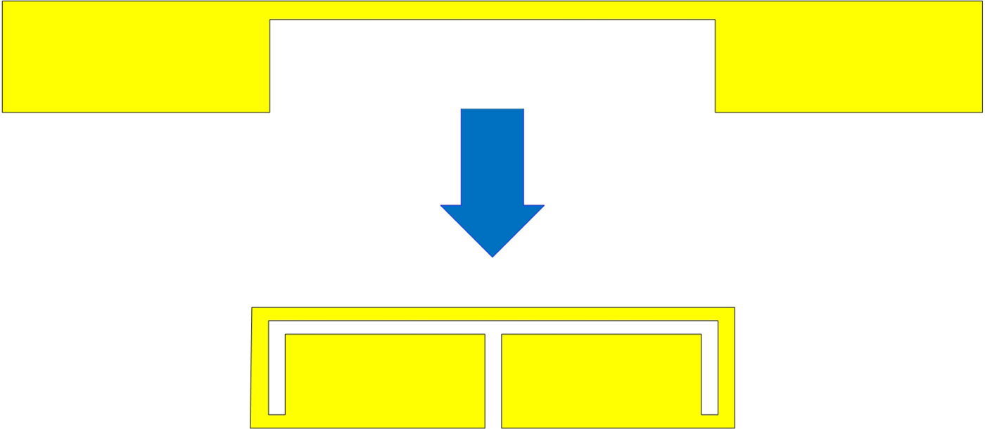
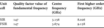
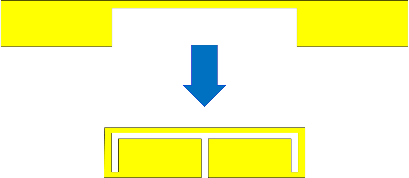
Figure 1 shows the evolution from a conventional SIR to FSIR. It can be seen that the FSIR can reduce the size about 50% compared with the conventional SIR, so that it is possible that a filter based on the FSIR can also reduce size about 50% or more synchronously compared with that of the SIR. Meanwhile, by simulating, the center frequency and the first higher order frequency of the FSIR are higher than that of the SIR, but the quality factor is almost same, shown in Table 1.
Evolution from conversional SIR to FSIR.
Comparison between SIR and FSIR folded by SIR.

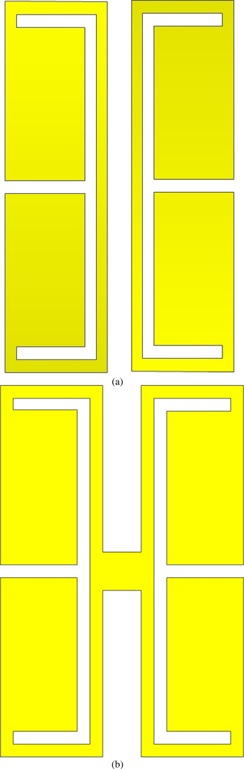
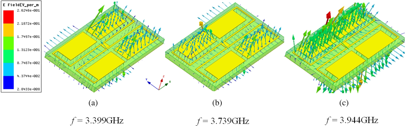
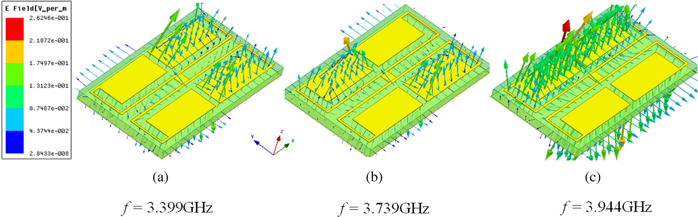
When two symmetrical independent FSIRs in Fig. 2(a) are arranged and connected by one small metal patch in the middle, a tri-mode resonator (TMR) can be constructed in Fig. 2(b) and its vector electric fields distributions with different resonant modes are shown in Fig. 3. It can be seen that the TMR has three resonant modes which are much more than those of two independent FSIRs.
(a) Two independent FSIRs are arranged symmetrically, (b) TMR which is designed with two independent FSIRs in (a) connected by one small metal patch.

Three resonant modes of TMR.
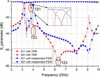
Compared with a filter constructed by only independent FSIR, a filter based on a TMR has additional three TZs (TZ1, TZ2, and TZ3) in Fig. 4, which can greatly enhance sideband selectivity.
A filter based on a TMR has additional three TZs compared with a filter based on the independent FSIR.

In Fig. 4, except three TZs, it can be found out that there is another narrow passband around 9.15 GHz, which is not needed if this filter is used in the frequency synthesizer to suppress high-order harmonic and high spurious frequency. So, it is necessary to add more TZs to suppress that passband.
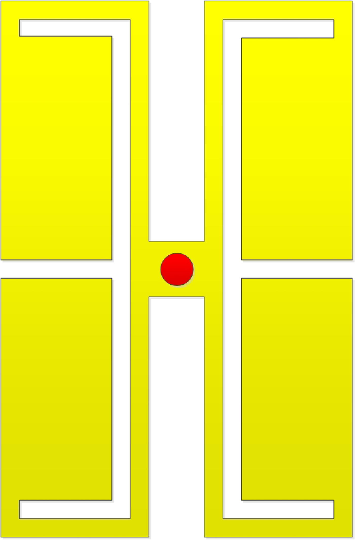
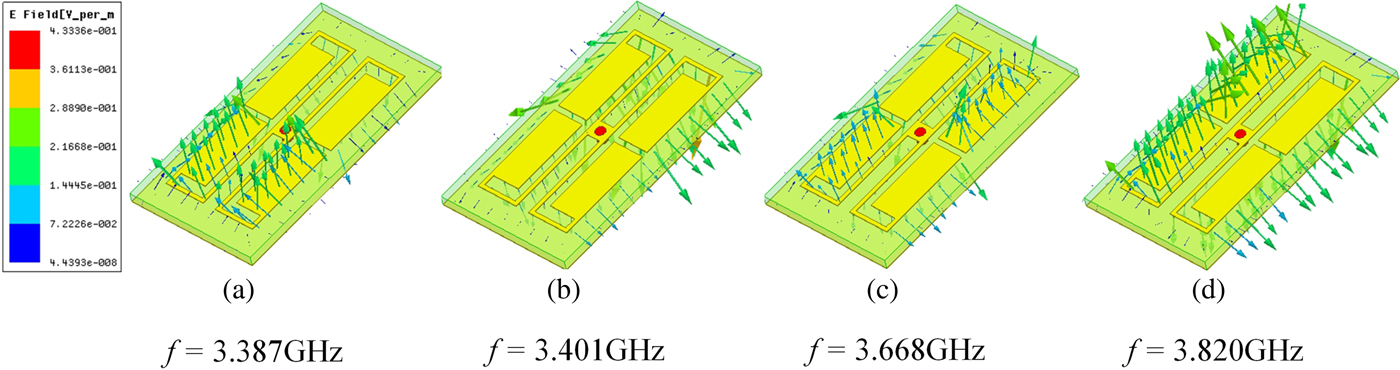
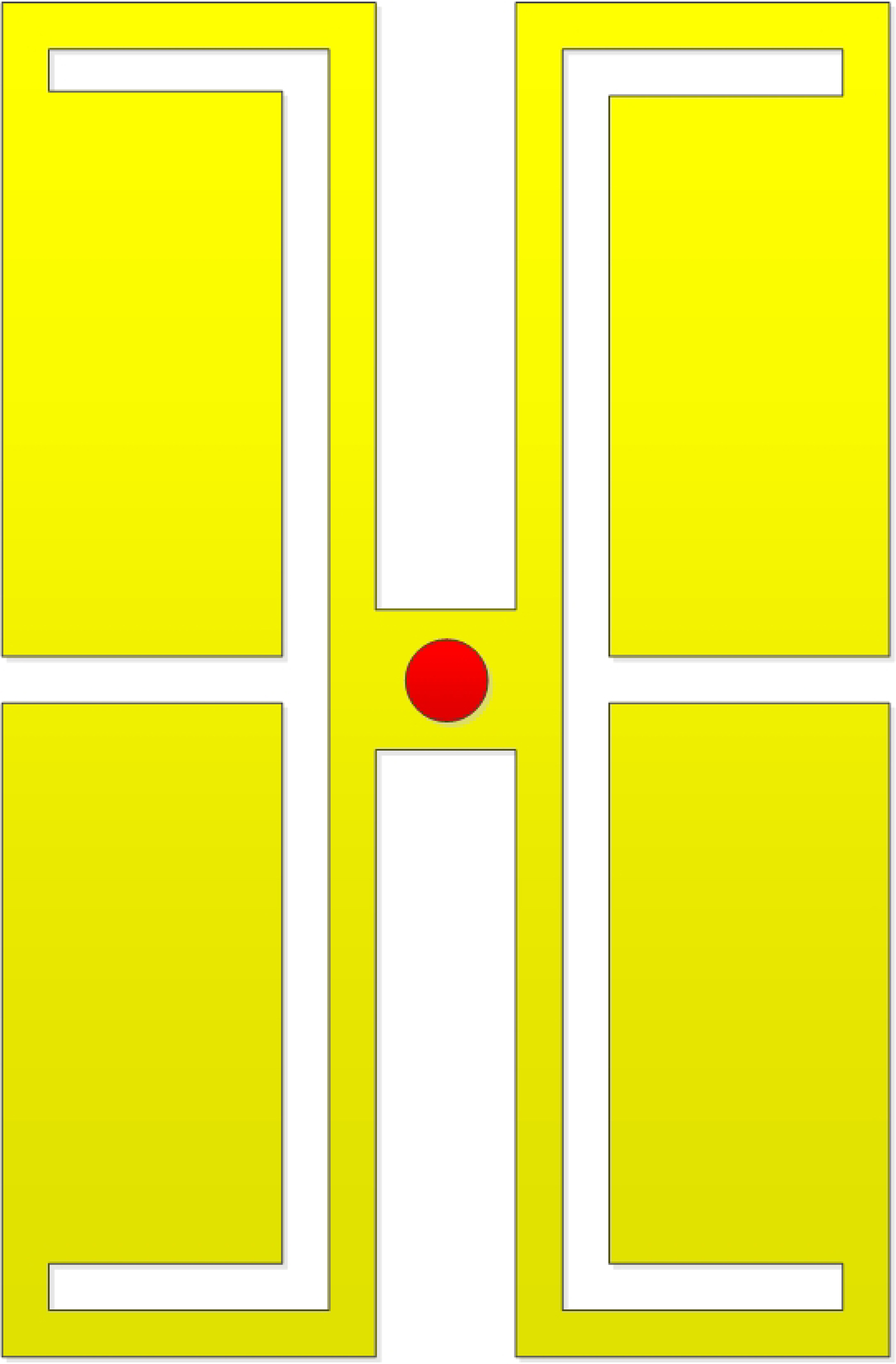
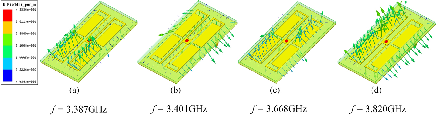
In this paper, an additional grounded metallized via hole is embedded at the center of the TMR to generate extra four TZs by four mixed electric and magnetic coupling paths. The detailed structure, named as tri-model resonator with via (TMRV), is shown in Fig. 5. Similarly, the vector electric fields distributions with different working modes of the TMRV are shown in Fig. 6. It can be seen that the TMRV has four resonant modes.
TMR with a grounded metallized via hole (TMRV).
Four resonant modes of the TMRV.
III. THE SIMULATION OF THE BANDPASS FILTER
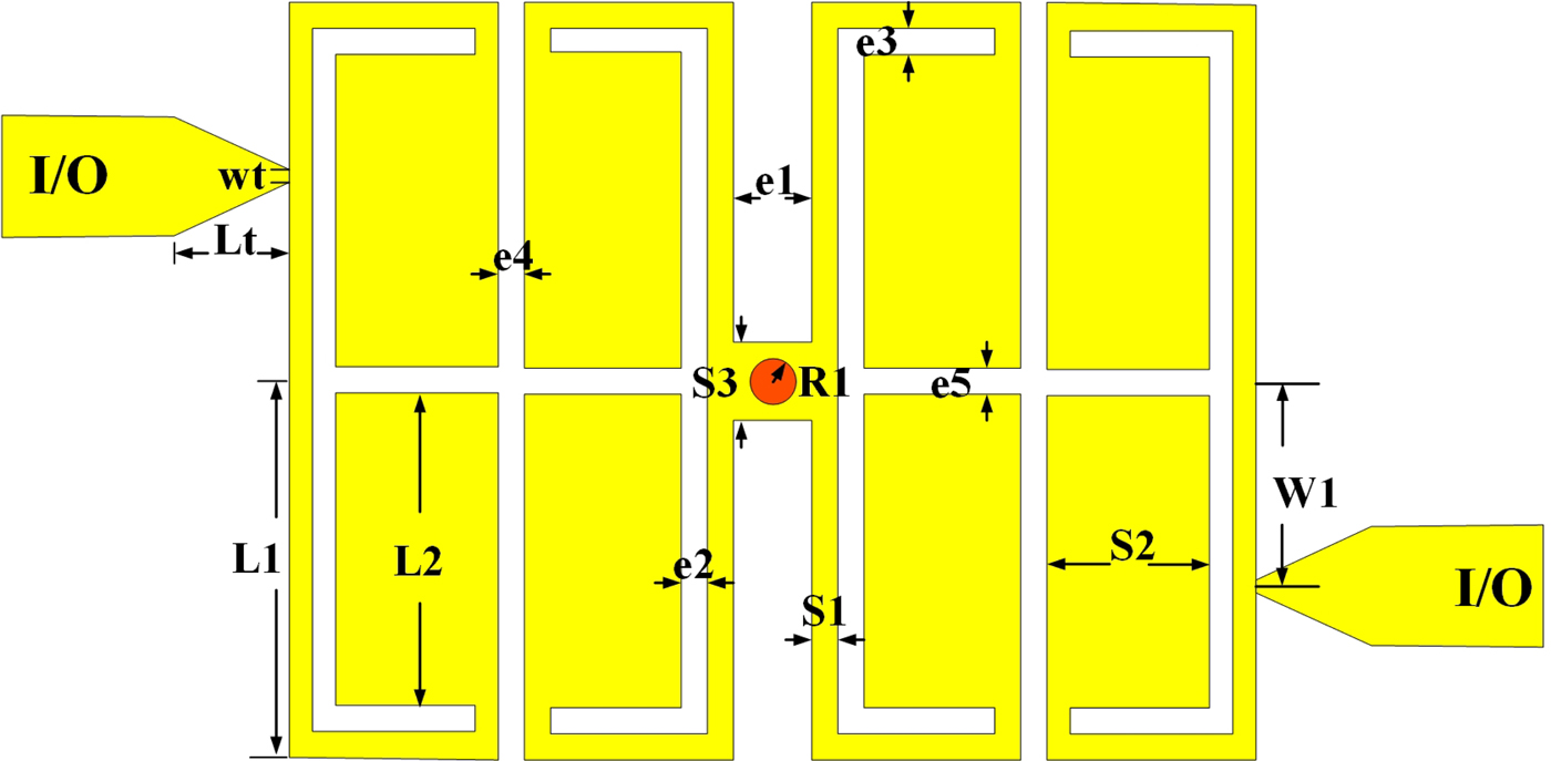
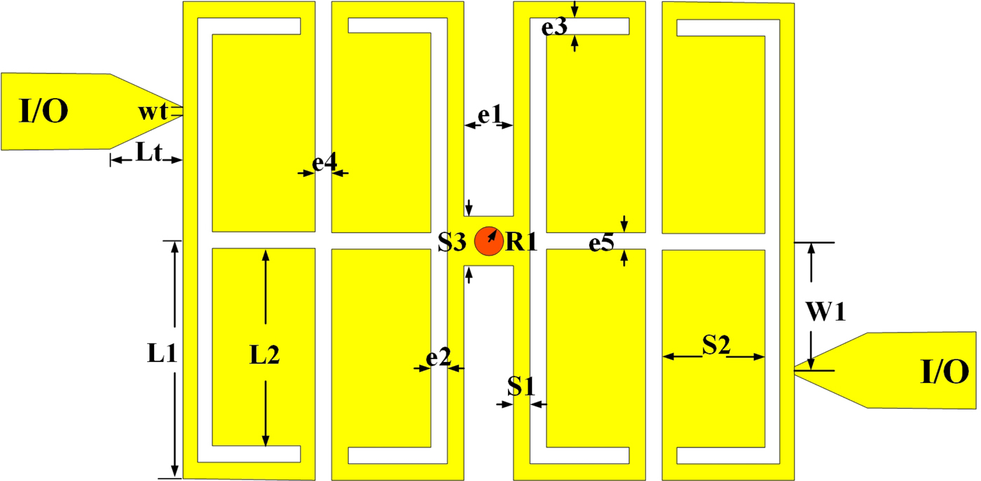
Based on the context analysis, a filter based on the TMRV is proposed in Fig. 7, which is composed of one TMRV, and two λ/2 FSIRs placed at input/output (I/O) ports.
The configuration of the proposed filter.
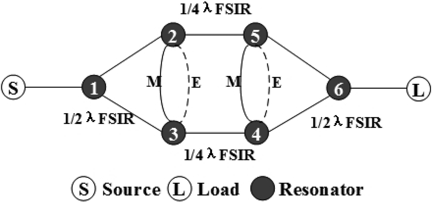
A detailed coupling scheme of the proposed filter is shown in Fig. 8. Resonators 1 and 6 are constructed by λ/2 FSIR, and Resonators 2, 3, 4, and 5 are constructed by λ/4 FSIR. Three pairs of cross-coupling paths can be gotten by the six resonators, which are path 1 → 2 → 5 → 6, path 1 → 3 → 4 → 6, path 1 → 2 → 5 → 4 → 6, path 1 → 2 → 3 → 4 → 6, path 1 → 3 → 4 → 5 → 6, and path 1 → 3 → 2 → 5 → 6, so that three cross-coupling TZs can be obtained according to [Reference Li and Ji16, Reference Wei, Jia, Zhu and Tang17]. Because the grounded metallized via hole, shared together by the four λ/4 FSIRs, can introduce mixed electric and magnetic coupling into the coupling path 2–3 and path 4–5, four mixed electric and magnetic coupling paths, i.e., path 1 → 2 → 5 → 4 → 6, path 1 → 2 → 3 → 4 → 6, path 1 → 3 → 4 → 5 → 6, and path 1 → 3 → 2 → 5 → 6, can produce four TZs according to [Reference Zhu, Hong, Chen and Wu18, Reference Wu, Chin, Che, Chang and Feng19]. Finally, the proposed filter can obtain seven TZs by the cross-coupling, and mixed electric and magnetic coupling, so that it is possible to obtain very high sideband selectivity and moderate stopband.
The coupling scheme of the proposed filter.

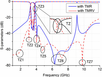
The filter with the TMRV are simulated and shown in Fig. 9. As comparison, the similar filter with TMR is also simulated and shown in Fig. 9. It is clear that the filter with the TMRV has additional four TZs, i.e., TZ1, TZ2, TZ5, and TZ7 which are introduced by the grounded metallized via hole. Whatever the filter with TMRV or TMR, its upper sideband selectivity is good. However, for the lower sideband selectivity, the filter with the TMR is relatively poorer than that with the TMRV, and the latter can improve 10–23 dB. Moreover, at 9.15 GHz or so, the filter with the TMRV has much better stopband rejection, about 33 dB than that with the TMR, because of the introduction of the mixed electric and magnetic coupling by the ground metaled via.
The simulated results of the filter with TMR and TMRV, where TZ1, TZ2, TZ5, and TZ7 are additional four TZs produced by mixed electric and magnetic coupling.

IV. EXPERIMENTS AND RESULTS
Optimized by commercial electromagnetic simulation software, the bandpass filter with the TMRV is centered at 3.5 GHz, and fabricated on the single-layer Rogers RT/Duroid 5880 substrate with a thickness of 0.508 mm, a relative permittivity ε r of 2.2 ± 0.02, and a loss tangent of 0.0009 by a standard PCB (printed circuit board) process. Its parameters in Fig. 7 are summarized as follows: s1 = 0.2, s2 = 1.6, s3 = 0.9, L1 = 5.2, L2 = 4.25, e1 = 0.7, e2 = 0.36, e3 = 0.6, e4 = 0.3, e5 = 0.3, wt = 0.2, Lt = 1.2, W1 = 2.6, and R1 = 0.25 (unit: mm). Agilent N5245A vector network analyzer is used to measure the filter with two 2.4 mm RF SMA connectors. Final photograph of the filter is shown in Fig. 10. By measurement, the size of the filter is 12.3 × 10.4 mm2, i.e. only about 0.21λ g × 0.18λ g , where λ g denotes the guided wavelength at central frequency. As comparison, the filter with the TMR is also fabricated with the same structure as that with the TMRV except the ground metaled via hole.
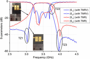
The measured S-parameter of the filter with TMR and TMRV in the local passband.

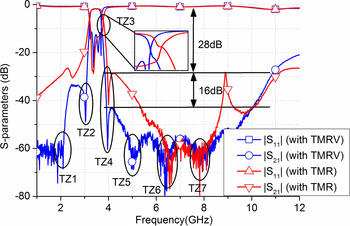
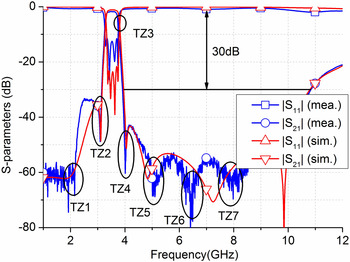
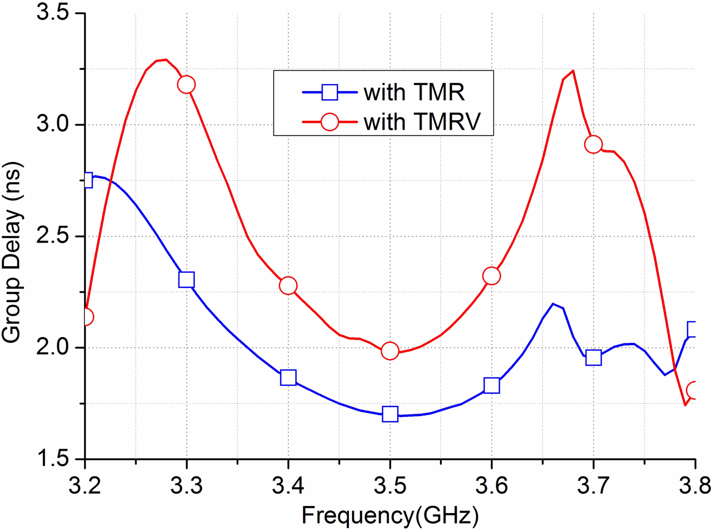
After fabrication, the S-parameters of the filter with the TMRV are shown in Figs 10–12. Its minimum measured insertion loss, including the additional loss of SMA connectors, is approximately 1.7 dB, which is about 0.6 dB worse than the simulated one. Meanwhile, a passband at a center frequency of 3.45 GHz with a fractional bandwidth about 11.6% is achieved. As shown in Fig. 10, its upper and lower sideband suppressions are both 45 dB at 450 and 390 MHz away from the center frequency. According to Fig. 12, its stopband is far away to the third harmonic of centre frequency with rejection from 30 to 55 dB. Moreover, it can be obtained easily from Fig. 10 that TZ2 is not so far away from the passband, which is a trade-off between return loss and TZ performance. Its measured group delay of S21 is shown in Fig. 13, and its jitter is only 2 ns.
The measured S-parameter of the filter with TMR and TMRV in the full interested frequency band.

The simulated and measured S-parameter of the filter with TMRV.

The group delay of the filter with TMR and TMRV.
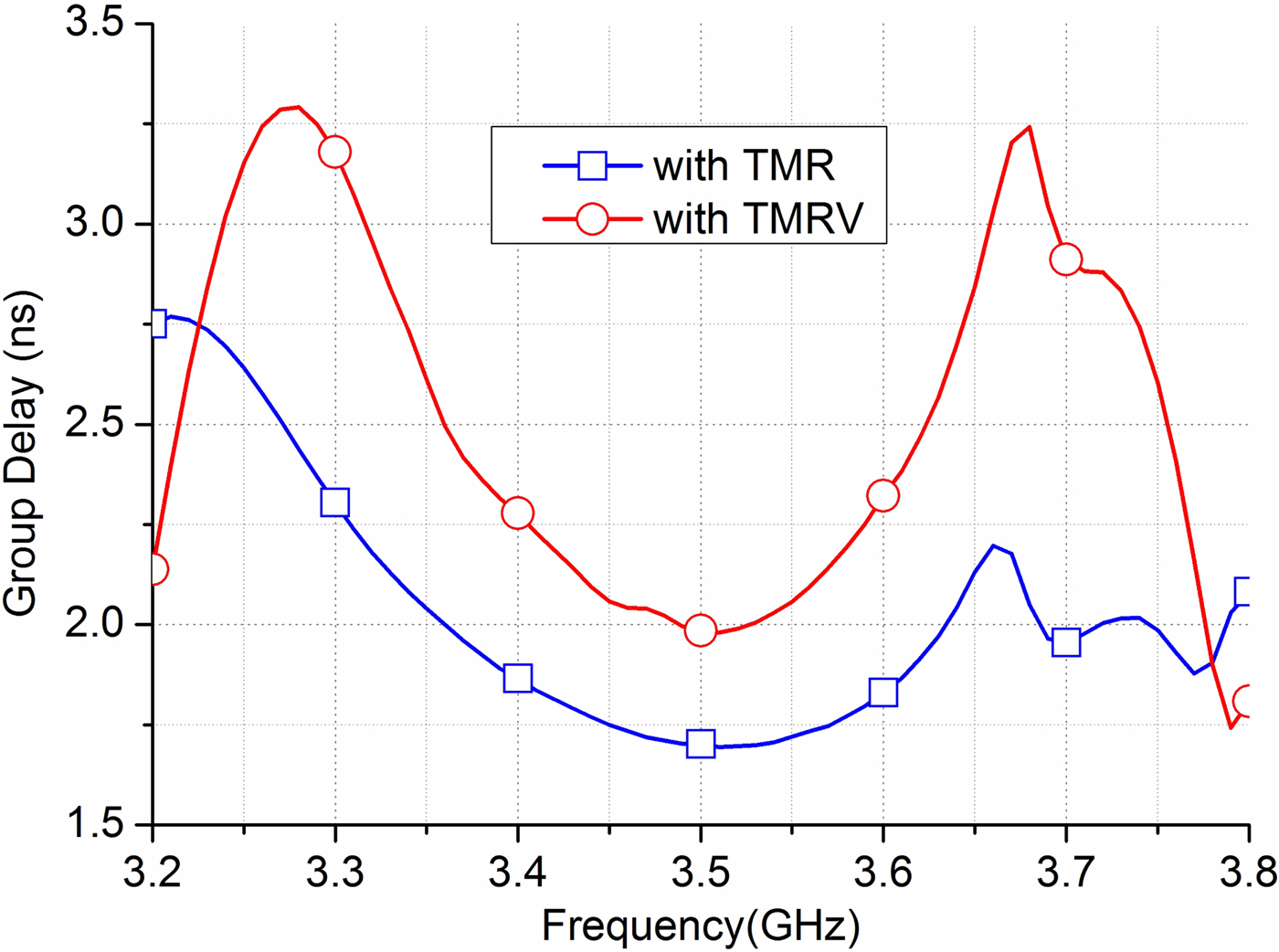
As comparison between S-parameters of the filters with the TMR and with the TMRV, the measured results have similar characteristics to the simulation ones. However, the group delay of the filter with the MRV is a little worse, about 1 ns, than that of the filter with the TMR.
It is obvious that the proposed filter with the TMRV can greatly improve the performance of sideband selectivity whatever upper or lower sideband as well as extend stopband up to three-order harmonic frequency.
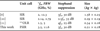
A detailed comparison, between this work and some previously reported compact bandpass filters with high selectivity and wide stopband, is listed in Table 2. The proposed filter outperforms all others in terms of the circuit size or stopband performance.
Comparison with reported bandpass filter.

* f 0 and FBW denote center frequency and fractional bandwidth, respectively.
** OLR denotes open-loop resonator.
V. CONCLUSION
In this paper, a 3.5 GHz size-miniaturized bandpass filter with the TMVR has been designed, fabricated and measured to purchase high sideband selectivity, moderate stopband and compact size. By comparatively analyzing with TMR, independent FSIR and SIR, it can be found out that some passive components, such as power dividers, filters and couplers, can be designed with the TMVR technology to suppress spurious and harmonic wave when collaborated with frequency multipliers and mixers in the frequency synthesizer application and transmitter of radar application.
ACKNOWLEDGEMENTS
The work is funded by Beyond Vision Detection (Chengdu) Sci. Tech. Co. LTD
 Tao Huang was born in xiangyan, hubei province,1987. He received the Bachelor and M.S. degree from the University of Electronic Science Technology of China (UESTC) in 2010 and 2013, respectively. Currently, he is learning as a Ph.D. student in the UESTC under the supervision of Professor Zhenhai Shao.
 Zhenhai Shao was born in Jiangsu, China, on December 1, 1971. He graduated from the Nanjing Normal University of China, Nanjing, China, in 1994. He received the M.S. and Ph.D. degrees from the Southeast University of China, Najing, China, in 1997 and 2000, respectively. From 2001 to April 2003, he was with Nanyang Technological University as research fellow. From 2003 to 2006, he was a manager and research scientist in Wireless Communications Laboratory, NICT Singapore representative office, National Institute of Information and Communications Technology, Japan. From May 2006 to December 2007, he was Chief Technical Officer in Cubic Micro Design Pte. Ltd. Currently, he is a professor in University of Electronic Science Technology of China and is concurrently holding a joint appointment in China Investment Association, China UAV Alliance and Sichuan Sicence Technology Association as Advisor as well as Visiting/Adjunct/Guest positions at Nanjing University of Aeronautics and Astronautics, Chongqing University of Posts and Telecommunications, and Bejing University of Posts and Telecommunications.
His research interests include microwave/millimeter-wave chip/subsystem, passive devices and circuits, numerical procedures of FDTD, TLM, TDFEM, and DSC method for passive microwave components, software design. He authored about 200 paper published in international journals and conference proceedings. He has been awarded by the program of ‘one hundred talented people’ of Hangzhou City and Nanjing City of China.
Dr. Shao is a Senior Member of IEEE, Guest Editor of Journal of China new industry, Guest Editor of International Journal of Mathematical Problem in Engineering, the founding General Chair of International Conference on Communication Problem-solving.