1. Introduction
As the global population ages and the number of individuals experiencing physical decline due to accidents or congenital conditions increases, the demand for assistive devices to aid in daily tasks is growing rapidly. Assistive robots play a critical role in meeting the demand, with safety in human–robot interaction as a top priority. Drawing inspiration from biological structures such as snakes, elephant trunks, and octopus tentacles [Reference Babin and Gosselin1–Reference Ding, Niu, Su, Yang, Liu, Gao and Deng3], these robots are designed with flexible joints to prevent injury in case of malfunction. The flexibility not only allows the robots to adapt to highly dynamic environments but also ensures safe and effective support for individuals with physical impairments.
Compared to traditional rigid robots, serial robots with flexible structures offer inherent compliance and, in theory, limitless degrees of freedom [Reference Giannaccini, Xiang, Atyabi, Theodoridis, Nefti-Meziani and Davis4–Reference Kang, Branson, Zheng, Guglielmino and Caldwell6]. These features enable them to cope with complex environments more efficiently and mitigate damage during collisions. In unstructured settings, the flexibility of these robots makes them one of the most promising solutions for ensuring safe operation [Reference Song, Xiao, Li, Zhang, Xue and Li7–Reference Fang, Chen, Tan, Ge, Zhao, Wang, Yuan and Wang9]. Consequently, flexible serial robots have been widely adopted in various fields, including human–robot interaction, medical rehabilitation, and explosive ordnance disposal.
Flexible serial robots can be controlled using multiple drive technologies [Reference Webster and Jones10], with cable and pneumatic drives being the most common [Reference Renda, Cianchetti, Giorelli, Arienti and Laschi11]. In Figure 1, the tensioned whole structure has the advantages of lightweight and high safety. While ensuring the flexibility of the robot, the stiffness of the robot can be improved by pretension and the stability of the robot structure can be improved [Reference Song, Lu, Zhao, Sun, Wang and Zhang12]. Flexible joints provide excellent compliance for the robot and stabilize the robot’s motion posture through uniform arrangement, while greatly reducing friction effects in motion through deformation bending, as well as ensuring safe human–machine interaction and efficient execution in complex environments due to the use of flexible materials. Therefore, the serial robot with flexible joints and tensegrity structures combines lightweight design and structural compliance with excellent adaptability and conformability. Its modular design also offers high scalability and flexible configuration, providing a reliable foundation for complex task applications. Future enhancements may involve equipping the robot’s end-effector with sensors, potentially broadening its applications to robotic arms for underwater exploration and space missions [Reference Liu, Shi, Chen, Cheng, Ding and Deng13].
Integration of flexible joints, tensegrity structure, and motion platform with three constraints.

In the kinematic analysis of traditional flexible serial robots, methods based on segmented constant curvature or static analysis are commonly employed [Reference Song, Sun, Zhao, Lu, Wang and Zhang14–Reference Song, Lu, Zhao, Sun, Wang and Zhang17]. These approaches primarily focus on analyzing the structure of flexible links. In contrast, this study utilizes a purely kinematic model based on geometric constraints to control the motion trajectory and position of the robot’s end-effector [Reference Falkenhahn, Mahl, Hildebrandt, Neumann and Sawodny18–Reference Camarillo, Milne, Carlson, Zinn and Salisbury20]. Gravagne et al. established an early kinematic model for cable-driven serial robots using differential geometry, elucidating the relationship between the robot’s posture and changes in cable length [Reference Rone and Ben-Tzvi21]. Furthermore, the review by Webster and Jones investigates various kinematic models for constant curvature robots, which are characterized by cables running parallel to the robot’s main body [Reference Song, Sun, Zhao, Lu, Wang and Zhang14].
In static–dynamic analysis, various methods have been developed to derive the dynamic models of serial robots, including the principle of virtual power, Cosserat rod theory, Beam theory, and Euler–Lagrange equation [Reference Falkenhahn, Hildebrandt, Neumann and Sawodny22–Reference Sadati, Naghibi, Shiva, Michael, Nanayakkara and Zschaler25]. The Cosserat rod theory represents serial robots as spatial curves subjected to shear, tension, and bending, resulting in a hyperbolic system described by partial differential equations. However, due to computational complexity, these models are typically assessed only under steady-state conditions [Reference Grazioso, Di Gironimo and Siciliano26]. To alleviate computational burdens, subsequent research introduced discretization methods for Cosserat rod theory [Reference Yang, Harsono and Yu27], which use recursive algorithms to decrease computational complexity. While these methods assume that the torsion and strain of each discrete element are constant, they may not accurately reflect the robot’s true behavior under external forces and changes in stiffness [Reference Luo, Yuan, Hu, Du, Bao and Zhou28]. Recently, Euler–Bernoulli theory [Reference Godage, Wirz, Walker and Webster29] and finite element methods [Reference Liu, Huang, Li, Hu and Jin30] have also been applied to dynamic modeling. However, these models involve numerous variables, making them difficult for real-time simulation or dynamic control. Energy-based virtual power principles [Reference Sadati, Naghibi, Shiva, Michael, Nanayakkara and Zschaler25] and Lagrangian dynamics [Reference Mu, Yuan, Xu, Liu and Liang31] are commonly employed to derive dynamic models, with the Lagrangian method integrating effects such as elasticity, gravity, and external torques into the dynamic equations, leading to the derivation of driving forces. The approach has been widely used in modeling and controlling large continuum robot systems, such as the Bionic Handling Assistant (BHA) of Festo [Reference Tiefeng, Mingyu, Guanjun, Libin and Qinghua32] and the OctArm [Reference Zhang, Li, Kan, Yuan, Rajabi, Wu, Peng and Wu33].
This study focuses on cable-driven serial robots with flexible joints and tensegrity structures, using geometric optimization and homogeneous transformation matrices for forward kinematic calculations. The optimized forward kinematics method demonstrates higher computational efficiency in simulations. Additionally, static–dynamic analysis of the robot is performed using force and torque balance equations, and kinetic energy variation curves are computed using the Jacobian matrix under specified motion trajectories. Notably, previous research has primarily concentrated on the analysis of parallel fixed-link structures [Reference Zheng, Branson, Guglielmino, Kang, Cerda, Cianchetti, Follador, Godage and Caldwell34]. Whereas this study addresses the analysis of non-fixed support link structures not covered in the literature, offering the following contributions:
-
(1) Optimized the forward kinematics for serial robots with tensegrity structures and flexible joints, enhancing simulation speed.
-
(2) Proposed optimized static–dynamics equations for cable-driven serial robots with flexible joints and tensegrity structures.
-
(3) Validated the accuracy of kinetic energy variation under motion trajectories in practical applications.
The structure of the study is as follows: Section 2 provides a brief introduction to cable-driven hybrid structure serial robots and analyzes their general kinematic models. Section 3 discusses the static–dynamic analysis of cable-driven hybrid structure serial robots in detail and establishes classical dynamic models. Section 4 constructs a simplified dynamic model to meet practical application needs and verifies its motion control effectiveness through simulations. Section 5 critically discusses the experimental results, and Section 6 summarizes the main conclusions of the study.
2. Kinematic analysis of cable-driven serial robots
This study presents a novel cable-driven serial robot that relies on flexible joints and a tensegrity structure, eliminating the traditional central main shaft design. The robot consists of flexible joints and a motion platform component, with the tensegrity structure providing self-support. The flexible joints are 3D-printed using materials with linear mechanical properties, effectively constraining the robot’s bending motion while providing two degrees of freedom for each joint.
2.1. Kinematic model
To improve modeling efficiency and the accuracy of parameter settings, the following assumptions were made in the kinematic analysis of the cable-driven serial robot:
-
Assumption 1. The flexible joints are made from linear elastic materials, and the bending angle is linearly related to the generated torque.
-
Assumption 2. Lubricating oil is present between the cables and between the cables and their respective holes, resulting in negligible frictional effects.
Based on the overall structure and design of the components shown in Figure 1, the motion platform consists of two parts. The upper part is used to fix the flexible joints, while the lower part is used to secure the drive cables that control the motion platform. As shown in Figure 2, a global coordinate system is established with the origin at the fixed motion platform Disk 0 . Local coordinate systems are established at each joint, labeled as Disk i . And i denotes the joint number, which can be 0, 1, 2, or 3, depending on the joint position. Based on the relative positions between the base Disk 0 and the various motion platforms Disk i shown in Figure 2, a homogeneous coordinate transformation matrix is established between them.
Motion state of the main structure. (a) Description of positions relative to the main structure’s vertical coordinate system and (b) bending direction and angle of the bending plane.

Coordinate systems and their corresponding positions.

In the bending motion state of the motion platform shown in Figure 3, the Z axis rotates around the joint point O
i
within the bending plane, resulting in an angle θ
i
between the rotated Z
i
′ axis and the Z axis. Additionally, in the X
i
, Y
i
, Z
i
coordinate system, the X
i
axis forms an angle
 $\psi$
i
with the bending plane. Based on these geometric relationships, the equation for the homogeneous transformation matrix T
i
i + 1
between different coordinate systems can be defined:
 \begin{equation} T_{i}=\left\{\begin{array}{c} T_{i}\enspace \enspace \left(i=0\right)\\ \prod _{i=0}^{3}T_{i}^{i-1}\left(i\geqslant 1\right) \end{array}\right. \end{equation}
 \begin{equation} \begin{array}{c} T_{i}=\left[\begin{array}{llll} a_{1} & a_{2} & a_{3} & 0\\ b_{1} & b_{2} & b_{3} & 0\\ c_{1} & c_{2} & c_{3} & \frac{l_{i}}{2}\\ 0 & 0 & 0 & 1 \end{array}\right]\left(i=0\right)\\[-5pt] \\ T_{i}^{i-1}=\left[\begin{array}{llll} a_{1} & a_{2} & a_{3} & 0\\ b_{1} & b_{2} & b_{3} & 0\\ c_{1} & c_{2} & c_{3} & l_{i}\\ 0 & 0 & 0 & 1 \end{array}\right]\left(\begin{array}{l} i\geqslant 1 \end{array}\right)\\[-5pt]\\ a_{1}=\left(\cos \left(\theta _{i}\right)-1\right)\cos \left(\psi _{i}\right)^{2}+1\\[5pt] a_{2}=b_{1}=\frac{1}{2}\sin \left(2\psi _{i}\right)\left(\cos \left(\theta _{i}\right)-1\right)\\[5pt] a_{3}=-c_{3}=\cos \left(\psi _{i}\right)\sin \left(\theta _{i}\right)\\[5pt] b_{2}=\left(\cos \left(\theta _{i}\right)-1\right)\sin \left(\psi _{i}\right)^{2}+1\\[5pt] b_{3}=-c_{2}=\sin \left(\psi _{i}\right)\sin \left(\theta _{i}\right)\\[5pt] c_{1}=\left(\cos \left(\theta _{i}\right)-1\right)\left(\cos \left(\psi _{i}\right)^{2}+\sin \left(\psi _{i}\right)^{2}\right)+1 \end{array} \end{equation}
Based on the main structure of the serial robot shown in Figure 2(a), Eq. (2) is substituted into Eq. (1) and the local coordinate systems are converted to the global coordinate system. Thus, using the two constraint angles θ
i
and
 $\psi$
i
for each joint, the homogeneous transformation matrices between each joint of the serial robot can be determined, which in turn defines the orientation of the main body in space. To improve computational efficiency, generalized vectors q
i
and Q
i
are defined, where q
i
represents the bending-related angles of the i-th joint and Q
i
describes the bending state from Disk
0
to Disk
i
:
 \begin{equation} \begin{array}{c} q_{i}=\left[\theta _{i},\psi _{i}\right]^{\textrm{T}}\\ Q_{i}=\left[q_{1},q_{2},\cdots ,q_{i}\right]^{\textrm{T}}\enspace \enspace \left(i\geqslant 1\right) \end{array} \end{equation}
In Figure 3, Disk i illustrates the relevant positions of the cable holes. Based on the local coordinate systems established on Disk i , the coordinates of points k i1 , k i2 , and k i3 are determined:
 \begin{equation} \left\{\begin{array}{c} k_{i1}=\left(-r_{p},0,0\right)^{\textrm{T}}\\ k_{i2}=\left(\dfrac{r_{p}}{2},-\dfrac{\sqrt{3}r_{p}}{2},0\right)^{\textrm{T}}\\ k_{i3}=\left(\dfrac{r_{p}}{2},\dfrac{\sqrt{3}r_{p}}{2},0\right)^{\textrm{T}} \end{array}\right.\enspace \enspace \left(i=1,\,\,2,\,\,3\right) \end{equation}
In the initial pose of the robot, the original length of the drive cable on the same Disk i is l oi . During the bending motion controlled by the cables, the cables remain in a straight line. By applying Eq. (1) to the coordinate transformation of Eq. (4), the lengths of the three cables controlling Disk i , denoted as l iu , where u represents the cable hole position, can be obtained:
 \begin{equation} l_{iu}=\| T_{i}k_{iu}-k_{0u}\| \,\,\,\left(u=1,\,\,2,\,\,3\right) \end{equation}
The lengths of the three cables for different joints can be calculated using Eq. (5). By adjusting the elongation and contraction of the cables, the pose of the serial robot can be changed. To determine the position of the end effector of the serial robot in different postures. Based on the bending state of the main body and the double-layer structure of Disk i shown in Figure 2(b), the end point of the serial robot is located at point P i in Figure 3. When i = 3, P 3 represents the final end-effector of the serial robot. The position P 3 in the global coordinate system can be obtained using Eq. (1) and Eq. (3):
 \begin{equation} \begin{array}{c} P_{3}=\left[0,0,\dfrac{l_{0}}{2}+\sum _{i=1}^{3}l_{i}\right]^{\textrm{T}}\\ P_{Q3}=T_{3}P_{3} \end{array} \end{equation}
where P Q3 is the coordinates of the end-effector point. Based on different states of Q i , a set of coordinates E Q3 can be obtained, which represents the range of task space that the end-effector of the serial robot can reach.
2.2. Kinetic energy equation of the robot
The initial posture of the serial robot is shown in Figure 2(a). When the end-effector moves to a certain point in the task space, the kinetic energy generated by the robot needs to be calculated based on each joint’s q i . During the bending process, the center point O i of each joint remains unchanged. The bending direction and angle of the joints are defined by the generalized vector q i , so the derivative of q i needs to be taken during the bending motion:
 \begin{equation} \dot{q}_{i}=\left[\dot{\theta }_{i},\dot{\psi }_{i}\right]^{\textrm{T}} \end{equation}
According to Eq. (7), the Jacobian matrix J i is used to calculate the linear and angular velocities of each joint:
 \begin{equation} \left[\begin{array}{l} V_{i}\\ \omega _{i} \end{array}\right]=J_{i}\dot{q}_{i} \end{equation}
In Eq. (8), the Jacobian matrix J i is derived from the end position E i and the angular velocity vector q i for each joint. The linear and angular velocities of each joint are calculated using J i (q i ) = jacobian(E i , q i ).
Before calculating the angular velocity, it is necessary to first solve for the moment of inertia of the serial robot. The moment of inertia is closely related to the axis of rotation of the joints and the mass distribution. Based on the robot structure shown in Figure 1, the moment of inertia matrix can be obtained:
 \begin{equation} \begin{array}{c} C_{i}=\left[\begin{array}{lll} C_{xx} & 0 & 0\\ 0 & C_{yy} & 0\\ 0 & 0 & C_{zz} \end{array}\right]\\[-5pt]\\ C_{xx}=C_{yy}=\dfrac{1}{4}m_{i}r_{p}^{2}\\[-5pt]\\ C_{zz}=\dfrac{1}{2}m_{i}r_{p}^{2} \end{array} \end{equation}
By combining Eq. (8) and Eq. (9) and referring to the kinetic energy theory in classical mechanics, the linear and angular kinetic energies of the serial robot are calculated, resulting in the kinetic energy of each joint:
 \begin{equation} \begin{array}{l} T_{V}=\dfrac{1}{2}m_{i}\| V_{i}\| ^{2}\\[-5pt] \\ T_{\omega }=\dfrac{1}{2}\omega _{i}^{\textrm{T}}C_{i}\omega _{i} \end{array} \end{equation}
Based on Eq. (10), the total kinetic energy T power of the serial robot during motion can be calculated, and by calculating the total kinetic energy, the robot’s motion trajectory can be simulated in terms of kinetic energy:
 \begin{equation} T_{\textit{power}}=T_{V}+T_{\omega } \end{equation}
3. Dynamics analysis of cable-driven serial robots
3.1. Static–dynamic analysis
In the dynamic analysis of the cable-driven serial robot presented in this study, the primary focus is on calculating the tension of the three cables during the robot’s bending process. Due to the innovative use of both a tensegrity structure and flexible joints in the robot’s design, it is essential to account for the maximum tension limit F i max in the cables within the tensegrity structure when analyzing cable forces. Different Disk i components use cables with varying tension limits. When i = 1, cables with a higher tension limit are selected, and as i increases, the maximum tension limit F i max gradually decreases.
Since the cables cannot provide support forces, this study utilizes Newton’s second law and the torque balance theory derived from the conservation of angular momentum to establish the proportional relationship between the forces exerted by the three cables driving the joint’s bending within a certain force range. For the flexible joint, the material’s linear elasticity properties indicate a linear correlation between the bending angle and rotational stiffness [Reference Webster and Jones10], enabling the calculation of the torque provided at various bending angles.
Analysis of tension structure cable force limits and flexible joint rotational stiffness.

To ensure that each joint has two degrees of freedom and can withstand relatively stable forces, this study designs each motion platform with three flexible joints, as shown in Figure 4. The number of flexible joints matches the number of drive cables, and these joints are evenly distributed with an angle of 120° between them. During the bending motion of the robot, the flexible joints provide the bending torque, while the gravity acting on the joints is supported by the tensegrity structure. Finite element simulation of a single flexible joint is conducted to determine the rotational stiffness values K θx , K θy , and K θz . Based on the position of the flexible joints shown in Figure 1, the rotational stiffness of the three flexible joints in the X i , Y i , and Z i directions is calculated using the rotation matrix R k :
 \begin{equation} K_{R}=\left[\begin{array}{lll} K_{\theta x} & 0 & 0\\ 0 & K_{\theta y} & 0\\ 0 & 0 & K_{\theta z} \end{array}\right] \end{equation}
 \begin{equation} R_{k}=\left[\begin{array}{lll} \cos \left(\phi \right) & -\sin \left(\phi \right) & 0\\ \sin \left(\phi \right) & \cos \left(\phi \right) & 0\\ 0 & 0 & 1 \end{array}\right]\left\{\begin{array}{l} k=1,\phi =120^{\circ}\\ k=2,\phi =-120^{\circ} \end{array}\right. \end{equation}
 \begin{equation} K_{all}=K_{R}+R_{1}K_{R}R_{1}^{\textrm{T}}+R_{2}K_{R}R_{2}^{\textrm{T}} \end{equation}
Eq. (12) and Eq. (13) are substituted into Eq. (14) to compute the rotational stiffness provided by the three flexible joints. Based on the generalized coordinates q
i
of each joint, the bending azimuth angle
 $\psi$
i
and the rotational angle θ
i
can be determined, leading to the joint’s axis vector during bending: d
r
= [−sin(
 $\psi$
i
); cos(
 $\psi$
i
); 0]. Further calculations can then be performed to determine the torque M
R
generated by the three flexible joints when the generalized vector is q
i
:
 \begin{equation} M_{R}=d_{r}^{\textrm{T}}\cdot K_{all}\cdot d_{r}\cdot \theta \end{equation}
Based on the torque balance theory in Newton’s second law, the bending torque provided by the flexible joints during bending motion can be calculated using Eq. (15):
 \begin{equation} \begin{array}{c} \sum \begin{array}{l} M_{all}=0 \end{array}\\ \sum _{c=1}^{3}F_{c}\times r_{c}+M_{R}=0 \end{array} \end{equation}
In Eq. (16), F
c
represents the cable tension vector, and r
c
is the vector from the center to the cable hole. By analyzing the force conditions of the tension structure shown in Figure 4, the proportional relationships between F
1
, F
2
, and F
3
can be determined. When the azimuth angle
 $\psi$
i
is 180° and the bending angle reaches its maximum value θ
max
, the tension structure relies on the maximum tension F
max
provided by the cables to support the entire weight of the moving platform. In the extreme state of θ
max
, Cable1 is the primary cable providing support. When Cable1 bears the maximum tension F
max
, the tension structure reaches its limit state, at which point the tension in Cable1, the gravitational force on the joints, and the cable tension vector F
c
are in equilibrium:
 \begin{equation} F_{\max }\sin \left(\theta _{\max }+\alpha \right)=G_{m}+\sum _{c=1}^{3}F_{Zc}\,\, \end{equation}
In Eq. (17), F Zc represents the component of the cable tension vector in the Z direction, and G m is the gravitational force vector acting on Disk i . By combining Eq. (16), the maximum force range FT max that the driving cables can endure can be determined. Since cables can only provide tension and their tension adjusts in real time based on actual needs, within the limited tension range of the tension structure, when satisfying Eq. (16) and maintaining the proportional relationship between F c , the minimum force range FT max of the driving cables can be calculated when F c is at its minimum value of 0.
3.2. Static–dynamic analysis
By using the force and torque expressions from Eq. (16) and Eq. (17), and applying Newtonian mechanics and Lagrangian dynamics, the standard form of the classical dynamic equations can be derived for calculating the dynamic characteristics of the serial robot:
 \begin{equation} H\left(q\right)\ddot{q}+B\left(q,\dot{q}\right)\dot{q}+G\left(q\right)=\lambda \end{equation}
The matrix H(q), which describes the inertia characteristics of the serial robot, is calculated as follows:
 \begin{equation} H\left(q\right)=\sum _{i=1}^{N}\left[\left(\frac{\delta \omega _{i}}{\delta \dot{q}}\right)^{\textrm{T}}\cdot C_{i}\cdot \frac{\delta \omega _{i}}{\delta \dot{q}}+m_{i}\cdot \left(\frac{\delta V_{i}}{\delta \dot{q}}\right)^{\textrm{T}}\cdot \frac{\delta V_{i}}{\delta \dot{q}}\right] \end{equation}
B(q), the Coriolis force matrix that primarily describes the non-inertial effects due to changes in velocity, is calculated as follows:
 \begin{equation} B\left(q,\dot{q}\right)=\frac{1}{2}\left(\frac{\delta H}{\delta q}q+\frac{\delta H}{\delta q}\dot{q}^{\textrm{T}}-\frac{\delta }{\delta t}\left(H\left(q\right)\dot{q}\right)\right) \end{equation}
G(q) is the gravity vector, representing the effect of gravity on the serial robot at Disk i . It is calculated as follows:
 \begin{equation} G\left(q\right)=\sum _{i=1}^{3}J_{i}\left(q_{i}\right)^{\textrm{T}}\cdot m_{i}\cdot g_{g} \end{equation}
In Eq. (21), g g = [0, 0, −g] T represents the gravitational acceleration vector. The external torques acting on the serial robot are produced by its three flexible joints. According to Eq. (16), the torques generated by the flexible joints during bending motion can be obtained, which further determines the parameter λ in Eq. (18):
 \begin{equation} \lambda =J_{i}\left(q_{i}\right)^{\textrm{T}}F_{c}-M_{R}+f_{ext} \end{equation}
In Eq. (22), f ext represents the frictional forces generated by the cables during the bending motion of the serial robot. Due to its minimal impact, it can be neglected in the dynamics model of the serial robot. By substituting Eqs. (19–22) into Eq. (18), the complete dynamics equation of the serial robot is obtained. When the tension in the drive cables is within the specified range, the generalized coordinates q i of the joints can be computed using Eq. (18). Additionally, based on the generalized coordinates q i , the end-effector positions and the overall posture of the serial robot in space can be further derived.
4. Kinematic and dynamic simulation verification
The innovative structure of flexible joints and tensegrity, along with the design of cable-driven serial robots, offers a new perspective in the field of serial robots. This paper performs kinematic and dynamic analyses for this type of serial robot, deriving its kinetic equations and dynamic models. In this section, MATLAB software is used for simulation verification, analyzing the robot’s spatial posture and motion trajectory, and evaluating the effects of the flexible joints and tensegrity structure through simulation.
As shown in Figure 1, the spatial posture of the cable-driven serial robot with flexible joints and tensegrity structure is analyzed through simulation. Additionally, for different values of q i , the forces and length changes of the three driving cables are simulated, and the workspace of the end position E i (i = 3) shown in Figure 3 is evaluated. Finally, by setting specific motion trajectories, simulations are conducted to verify the end-effector positions and kinetic energy variations of the serial robot.
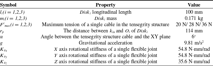
Based on the given basic parameters of the serial robot and the data in Table I, kinematic and dynamic simulations were performed using MATLAB. Starting from the initial upright position and transitioning to the final position shown in Figure 2(b), the simulation results illustrate the changes in the robot’s spatial posture. Each joint’s value q
i
was set according to the specified angles, with the maximum bending angle θ
z
assumed to be the maximum. For the design of the flexible joints, the maximum bending angle θ
i
was set to 15°, and the azimuth angle
 $\psi$
i
was set to 0°.
Basic parameters of the serial robot.

Figure 5 shows the results of the MATLAB simulation of the serial robot’s posture depicted in Figure 2(b). It illustrates the changes in the overall structure’s pose and the proportional relationship of cable lengths when each joint’s bending angle reaches its maximum. Based on this proportional relationship and the initial cable lengths in the upright position, the lengths of the cables for each joint Disk i were determined.
Simulation of the serial robot’s spatial posture.

Based on the simulation results in Figure 5, further analysis was conducted on the cable tension and length of the serial robot at different postures. During the simulation, all joint angle variables q
i
were kept constant, focusing primarily on the cable tension and length of Disk
3
. Considering the range of rotation angles θ
i
from 0° to 15° and the values of
 $\psi$
i
ranging from 0° to 360°, the cable tension and length in different postures of the robot were calculated using Eq. (5) and Eqs. (16–17). The simulation results are shown in Figure 6.
The relationship between the variations in the drive cable tension values and length values of Disk 3.

In Figure 6, the tension and length of the three cables driven by Disk 3 exhibit a sinusoidal relationship. As θ i increases, both cable tension and length increase. At the same θ i , there is an inverse relationship between tension and length. And, as the tension increases, the cable length decreases. This complementary behavior is consistent with the expected motion characteristics.
To provide a more intuitive demonstration of the motion characteristics of a single joint, a simulation analysis of the cable tension and length for Disk 1 was conducted separately (Figure 4). Since the tension structure of Disk 1 needs to support the entire weight from the upper platform, a cable with a maximum tension of 36N was used. During the simulation, the other motion platforms remained stationary in their initial state to highlight the motion performance of the single joint Disk 1 , thereby validating the simulation of Disk 1 .
Based on the simulation process described above, when Disk 1 is in motion and the other motion platforms remain in their initial state, the gravity of these platforms will exert an additional torque on the bent Disk 1 . Eq. (16) is applicable only to a single motion platform. For a system with multiple interconnected Disk i , the additional moments due to the gravitational forces of other platforms acting on Disk 1 need to be considered. In this case, the torque balance equation can be expressed as follows:
 \begin{equation} \sum _{c=1}^{3}F_{c}\times r_{c}+M_{R}=M_{G} \end{equation}
In Eq. (23), an additional moment M G due to gravity is introduced, which acts on Disk 1 compared to Eq. (16). The remaining motion platforms, composed of multiple Disk i , have their mass points considered as point U p in Figure 2(a), with their gravitational force acting at point O 1 . By transforming points U p and O 1 to the global coordinate system, the lever arm l G for the moment M G applied to Disk 1 can be calculated:
 \begin{equation} \begin{array}{c} U_{p}=\left[0,0,l_{1}+\dfrac{l_{2}}{2}\right]^{\textrm{T}}\\[-5pt]\\ O_{1}=\left[0,0,\dfrac{l_{0}}{2}\right]^{\textrm{T}}\\[-5pt]\\ l_{G}=\left(U_{p}-O_{1}\right)T_{1} \end{array} \end{equation}
Based on the torque calculation equation in Newtonian classical mechanics and the fact that the lever arm of M G is perpendicular to the gravity vector G m , the values l G and L G , which are perpendicular to G m , can be determined:
 \begin{equation} L_{G}=\left[l_{G}\left(1\right),\,l_{G}\left(2\right),0\right]^{\textrm{T}} \end{equation}
Combining Eq. (24) and Eq. (25), the additional moment M G generated by gravity can be determined:
 \begin{equation} 2\cdot G_{m}\times L_{G}=M_{G} \end{equation}
Additionally, based on the tension range of the driving cables proposed in the dynamics analysis and the analysis under the condition of Eq. (23), the minimum tension required for the driving cables can be calculated. By combining with Eq. (17), the force balance equation for Disk 1 can be determined:
 \begin{equation} \sum _{c=1}^{3}F_{Zc}+3G_{m}=F_{\max }\cdot \sin \left(\theta _{\max }+\alpha \right) \end{equation}
By substituting Eq. (25) and Eq. (26) into Eq. (23) and combining it with Eq. (27), the characteristic of tensioned structure cables was utilized that adaptively provide tension within the limit tension range. This allows us to obtain the maximum tension value for the single driving cable when Cable1 reaches its limit tension. When Eq. (23) is satisfied and the tension of a single driving cable is 0, the minimum tension range for the three driving cables can be obtained. Subsequently, the cable lengths are analyzed through simulations, and the variation relationship between the driving cable tension values and length values is compared.
By considering the variations in static force and length of the driving cables in Figure 7, along with the interrelationship among the three cables in Figure 6, it can be concluded that the static force and length of the cables in Figure 6 exhibit a complementary relationship. In contrast, in Figure 7, the static force and length of the cables show similar surface variations. These two distinct variation patterns are primarily due to the additional torque M
G
exerted on Disk
1
by the gravity of Disk
i
. Based on Figure 7, three key observations were drawn. First, when the cable length increases, its tension also increases correspondingly. At this point, the torque provided by the cable, along with the torque from the flexible joint, collectively resists the additional torque M
G
, which aligns with the expected outcome. Second, as the bending angle θ
i
decreases, the overall bending amplitude of the robot reduces, leading to a corresponding decrease in the changes of both cable tension and length. This reduces the deformation of the flexible joint, diminishing the torque it provides, and thus the driving cable applies less force to maintain torque balance. Finally, when θ
i
is fixed, with the variation of
 $\psi$
i
, the tension and length curves of the three cables exhibit trigonometric function patterns, and the curves of both are similar.
Disk 1 cable static force and length diagram.

By comparing the simulation results in Figs. 6 and 7, the force variation range of the driving cable controlling Disk 3 is 0∼1.71 N, while the force variation range of the driving cable controlling Disk 1 is 0∼2.04 N. This indicates that the addition of the additional torque M G increases the range of cable force variation. Moreover, the amplitude of the curve variation in Figure 7 is greater than that in Figure 6, suggesting that the control accuracy of Disk 1 is higher than that of Disk 3 during the motion of the serial robot. Based on the simulation process and the balance equations of force and torque, the same principle can be applied to derive the static force and length variation curves for the driving cables of Disk 2 . By adjusting the lengths of the driving cables for different joints and providing corresponding tension, the end-effector of the serial robot can be guided to reach a designated position in space. When the robot is composed of three serially connected joint sets, simulations can be performed for each joint under different q i values based on Eq. (6), resulting in the discrete points that the end-effector can reach (Figure 8).
Workspace of the end-effector.

In Figure 8, when the serial robot consists of three joints, the work area of the end-effector in the X i Y i plane reaches up to π/100 m2 and the work range in the Z i axis direction varies approximately by 0.03 m. The comprehensive analysis of its workspace and numerical values indicates that this type of serial robot structure can better adapt to changing environmental conditions.
To validate the performance of the proposed serial robot during motion [Reference Zheng, Branson, Guglielmino, Kang, Cerda, Cianchetti, Follador, Godage and Caldwell34], three motion trajectories were defined in the spatial domain, based on the robot’s human–robot interaction application scenarios. These trajectories simulate arm swings, circular motions, and movements along complex curves. By progressively increasing trajectory complexity from simple planar motion to intricate spatial movements, this approach enables a comprehensive evaluation of the robot’s motion performance. Simultaneously, the robot’s end-effector P 3 was simulated along the three trajectories. The robot’s kinetic energy and the positional coordinates of P 3 were analyzed during the motion to validate its performance.
Figures 9–11 illustrate the variations in kinetic energy and displacement curves of the robot’s end-effector in the global coordinate system under three different motion trajectories.
The kinetic energy and coordinate changes of the end-effector along Trajectory 1.

The kinetic energy and coordinate changes of the end-effector along Trajectory 2.

The kinetic energy and coordinate changes of the end-effector along Trajectory 3.

In Figure 9, Trajectory 1 follows a single-plane linear motion. The robot starts from the initial position G
1
with zero velocity, undergoes an acceleration and deceleration process to complete phase A
1
, and then returns to the starting position before proceeding with phase B
1
. After completing B
1
and returning to the initial point, Trajectory 1 is fully executed. Figure 10 presents Trajectory 2, which consists of four key stages: G
2
, A
2
, B
2
, and C
2
. At transition points A
2
, B
2
, and C
2
, the robot’s motion state switches sequentially – from θ
i
rotation to
 $\psi$
i
rotation and back to θ
i
rotation. Due to these transitions, the velocity at these points drops to zero, and each stage involves a process of acceleration followed by deceleration. Figure 11 depicts Trajectory 3, which follows an infinity (∞) shape and is divided into two phases: A
3
and B
3
. The robot starts at G
3
with zero velocity, completes phase A
3
, and returns to G
3
, where the velocity again reaches zero. It then transitions into phase B
3
to complete the full trajectory.
From the kinetic energy variation curves in Figs. 9–11, it can be seen that Trajectory 1 primarily involves θ
i
bending, and its kinetic energy value is significantly lower than the middle portion of Trajectory 2. Combined with the kinetic energy variation of Trajectory 3, the kinetic energy generated by θ
i
rotation is much smaller than that generated by
 $\psi$
i
rotation. Therefore, during the motion process, changes in the angle
 $\psi$
i
contribute significantly more to the kinetic energy than changes in the angle θ
i
.
Based on the results of the simulation experiments, an experimental platform was constructed (as shown in Figure 12), and prototype experiments were conducted to verify the feasibility and accuracy of the proposed kinematic model. During the experiments, the three motion trajectories shown in Figs. 9–11 – single-plane curve, dual-plane curve, and spatial curve – were sequentially executed. By utilizing the experimental platform, the kinematic model was input into the host computer to control the prototype, ensuring the precise execution of the motion trajectories in Figs. 9–11, thereby further validating the effectiveness of the model.
Design and development of a serial robot prototype.

As shown in Figure 13, prototype experiments were conducted to obtain comparative plots of input signals and motor feedback signals for different motion trajectories, along with their corresponding error graphs. By analyzing these comparisons, it is evident that the motor exhibits excellent tracking performance. Furthermore, the stability of the feedback signal curves indicates smooth robot motion, further validating the robustness of the proposed kinematic model.
Motor input signal, feedback signal, and error signal graphs: (a) single-plane motion trajectory, (b) dual-plane motion trajectory, and (c) spatial motion trajectory.

Examining the error curves for each motion trajectory, although some fluctuations are present, their magnitude remains relatively small compared to the corresponding cable length values in the motor feedback signals. As a result, the impact on the robot’s motion accuracy remains within an acceptable range. These findings strongly confirm the precision of the proposed kinematic model.
Based on the analysis of the input signals and motor feedback signals shown above, it can be ensured that the robot performs smooth trajectory motion during operation. For the motion performance of the serial robot, in addition to stability, it is also essential to ensure that the end-effector can accurately follow the desired trajectory. Therefore, trajectory tracking accuracy tests were conducted on the serial robot. Following the predefined trajectories, prototype experiments were carried out, and the motion trajectories of the end-effector were recorded to verify the accuracy of the theoretical modeling of the serial robot.
As shown in Figure 14, the motion curves of the prototype machine of this series–parallel robot under three typical trajectories are presented. By comparing the input signals in Figure 13 with the motor feedback signals, the accuracy of the established kinematic model was verified. Additionally, by comparing the simulated trajectories in Figs. 9–11 with the prototype machine trajectories in Figure 14, the correctness and feasibility of the proposed new series–parallel robot structure and its excellent motion performance were further confirmed.
Three types of arc trajectory motion diagrams: (a) single-plane arc trajectory motion, (b) two-plane curved trajectory motion, and (c) space multi-arcline trajectory motion.

5. Discussions
Based on the results of the experimental simulations, the end-effector of the robot can reach the desired spatial positions. However, the analysis of the kinetic energy variation curves for different trajectories shows that the kinetic energy generated by changes in
 $\psi$
i
is significantly greater than that generated by changes in θ
i
. This phenomenon may cause excessive vibrations during the robot’s movement, particularly during
 $\psi$
i
angle motion, making it difficult to precisely control the posture of the robot. Uncontrolled vibrations can reduce dynamic performance and introduce errors. Additionally, there is a certain level of error in the rotational stiffness of the flexible joints. According to Eq. (12) and the error rate µ of the rotational stiffness of the flexible joints, the rotational stiffness error provided by the flexible joints is calculated:
 \begin{equation} \Delta K_{R}=\left[\begin{array}{lll} K_{\theta x} & 0 & 0\\ 0 & K_{\theta y} & 0\\ 0 & 0 & K_{\theta z} \end{array}\right]\cdot \mu \end{equation}
By substituting Eq. (28) into Eqs. (14–16), the new torque balance equation is derived:
 \begin{equation} \sum _{c=1}^{3}\Delta F_{c}\times r_{c}+\Delta m_{R}=0 \end{equation}
Based on Eq. (29), the impact range of the rotational stiffness error rate on the driving cable forces can be determined. And the cable length changes
 $\Delta$
l
c
caused by different q
i
can be further analyzed:
 \begin{equation} \Delta l_{c}=l_{iu}-l_{oi} \end{equation}
Eq. (17) and Eqs. (29–30) are combined to solve for the power error range
 $\Delta$
W of the driving cables, which is caused by the rotational stiffness error rate µ of the flexible joints:
 \begin{equation} \Delta W_{c}=\Delta F_{c}\cdot \; \Delta l_{c} \end{equation}
Under a rotational stiffness error rate µ of 10%, its impact on the driving motor’s output power during the control process of the serial robot is analyzed, and the error range of the output power is evaluated through simulation.
As shown in Figure 15, the output power error in the driving cables caused by the stiffness error of the flexible joints is very minimal and has almost no significant impact on the robot’s motion control. The error value is negligible within the control system. Additionally, energy losses due to deformation are also considered negligible in their effect on the serial robot’s motion. The kinetic energy calculations in this study assume that the friction effects in the system are ignored. In practical operations, friction is typically reduced using lubricants and by minimizing the contact area of the drive path, while self-lubricating bushings are employed at cable fixation points to minimize the impact of friction on kinetic energy and the precision of the end-effector.
The range of error in the output power of the driving cables.

In summary, to further enhance the accuracy of the end-effector in the serial robot, incorporating the Coulomb model and the LuGre model to compensate for system friction is recommended. Additionally, improvements should be focused on the control of the driving cables and the fabrication of flexible joints. It is also crucial to note that the motion time in trajectory simulations may vary due to differences in computer configurations or processor performance.
6. Conclusions
This paper presents an innovative bionics-inspired design of a cable-driven serial robot, featuring a novel integration of tensegrity structures with flexible joints. This unique configuration significantly reduces the robot’s weight while enhancing its motion performance. The modular assembly approach provides the robot with high scalability and flexible configuration capabilities, effectively addressing adaptability challenges in complex environments. The uniform arrangement of tensegrity structures and flexible joints achieves an optimal balance between structural stiffness and compliance, thereby optimizing the overall mechanical performance.
A major contribution of this study lies in the design of a new serial robot configuration, as well as the development and optimization of forward kinematics and static–dynamics models that incorporate flexible components, effectively improving motion accuracy and stability. Additionally, a dynamic model was established to obtain real-time velocity and acceleration data, providing a theoretical foundation for precise trajectory control. Trajectory planning and prototype experiments verified the accuracy of the kinematic model, further confirming the feasibility and excellent motion performance of the proposed robot structure.
This research offers a pioneering structural design paradigm for lightweight, flexible, and highly adaptable robots. It not only provides theoretical support for the design and control of cable-driven serial robots but also expands the application scope of flexible robotics, laying a foundation for the development of robotic systems suited for complex and dynamic task environments in the future.
Future work will focus on further optimizing the robot’s structure and incorporating a mechanical claw at the end-effector to facilitate airborne grasping. Improvements in material selection will aim to enhance bending compliance and extend the bending range, thereby expanding the robot’s operational workspace. Additionally, factors such as friction will be integrated into the model, and sensors will be added to the actuator’s end to enable negative feedback control, improving the model’s precision and applicability. This research proposes a novel design and control framework for cable-driven serial robots, with significant potential for broader applications in the flexible robotics field.
Author contributions
SD and WHC conceived and designed the study. WHC and CH wrote the article. SD, WHC, CH, LM, and ZLX assisted in the analysis of simulation results. All authors read and approved the final manuscript.
Financial support
This work was supported by the Natural Science Foundation of Jilin Province (Grant No. YDZJ202301ZYTS272).
Competing interest
The authors declare that the work presented in this manuscript does not present conflicts of interest with other individuals or organizations in terms of benefits.
Ethical approval
Not applicable.