
I. INTRODUCTION
The rapidly increasing commercial electronic device market and application of renewable but intermittent energy supplies (e.g., sunlight, wind, and tide) give rise to a high demand of highly efficient electrochemical energy storage devices that can provide large energy density as well as high-power density simultaneously.Reference Zhai, Wan, Sun, Chen, Sun, Xia and Xia1–Reference Huang, Lethien, Pinaud, Brousse, Laloo, Turq, Respaud, Demortière, Daffos, Taberna, Chaudret, Gogotsi and Simon5 Supercapacitors (SCs), also known as electrochemical capacitors, have attracted intensive attention in decades for its capability of storing and delivering energy in seconds. Generally, the SCs are able to deliver 1–2 orders of magnitude higher in power density than Li ion batteries (LIBs), 2–3 orders of magnitude better in superior cycle lifetime than LIBs, and almost 3–4 orders of magnitude larger in energy density than conventional capacitors. Based on the energy storage mechanisms of SCs, two major categories were classified. One is the pseudocapacitor, where the capacitance comes from the fast and reversible faradic reactions taken place at surface and near surface of pseudocapacitive materials.Reference Zhai, Lu, Wang, Wang, Mathis, Liu, Li, Tong and Li6,Reference Xiao, Song, Lin, Zhou, Zhan, Hu, Zhang, Sun, Yang, Li, Jiao, Zhou, Tang and Gogotsi7 Despite high-theoretical capacitance raised from pairs of redox species, the practical capacitance of pseudocapacitive materials at high-charge/discharge rates is limited by the poor electronic and ionic conductivity.Reference Zhai, Lu, Ling, Yu, Wang, Liu, Liang, Tong and Li8 Alternatively, the other category based on electrical double layer (EDL) materials is able to be charged and discharged more rapidly than pseudocapacitive materials due to their high conductivity.Reference Zhang, Liu, Hou, Kou, Yue, Guan and Li9,Reference Zhao, Jiang, Fan, Liu, Zhuo, Wang, Wu, Yang, Ma and Hu10 The capacitance of EDL materials originates from the charge accumulation at the electrode/electrolyte interface, making it highly dependent on the surface area of EDL materials.Reference Oschatz, Boukhalfa, Nickel, Hofmann, Fischer, Yushin and Kaskel11 Therefore, the increase of porosity or creation of multiscale pores is efficient in improving the capacitance at high-charge/discharge rates.
Graphene with a combination of high surface area, flexibility, and electronic and thermal conductivity is emerging as an attractive and versatile material for SCs.Reference Wu, Tan, Zheng, Wang, Parvez, Qin, Shi, Sun, Bao, Feng and Müllen12 Atomic monolayer graphene, however, tends to restack during the synthesis procedure, thus leading to significantly reduced surface area as compared to the theoretical value of 2630 m2/g.Reference Wu, Zheng, Zheng, Wang, Sun, Parvez, Ikeda, Bao, Müllen and Feng13 Various strategies have been proposed for the agglomeration issues. One efficient option appears to be the creation of pores in different scales such as micropores (<2 nm), mesopores (2–50 nm), and macropores (>50 nm) to expand the graphene layer and/or make restacked graphene accessible to electrolyte ions.Reference Zhang, Liu, Li, Yu, Luo, Tong and Li14 Increased amounts of micropores can give rise to a substantially high surface area and accordingly high capacitance. For example, Kim et al.Reference Kim, Jung, Yoo, Suh and Ruoff15 reported that activated graphene-based carbons with a large amount of micropores less than 1 nm possess a specific surface area of up to 3300 m2/g, which could further lead to a high-theoretical EDL capacitance of ∼660 F/g. However, the high surface area mainly originated from micropores is not fully accessible to electrolyte ions, especially at higher charge/discharge rates. The aforementioned activated graphene-based carbons finally delivered a capacitance of 172 F/g at a current density of 2 A/g. The pore wall of micropores may hinder the ion transportation.Reference Zhang, Liu, Li, Yu, Luo, Tong and Li14,Reference Dutta, Bhaumik and Wu16 Very recently, Forse et al.Reference Forse, Griffin, Merlet, Carretero-Gonzalez, Raji, Trease and Grey17 demonstrated that pores with a diameter larger than 2 nm were beneficial for alleviating ion confinement inside micropores, which notably increased the capacitance at high-charge/discharge rates. Therefore, graphene with a multiscale or hierarchical porous structure should be highly efficient for both specific capacitance and power output.
Considering the rapid advances for portable and wearable electronics, the energy density of SCs per unit of volume is urgently needed to be boosted. However, volumetric capacitances of carbon-based electrodes are generally less than 100 F/cm3, thus leading to 5–8 W h/L for most commercially available SCs, which are much lower than that of lead-acid batteries (50–90 W h/L). Developing electrodes with high capacitance at large packing density is efficient for device to achieve high-volumetric performance. Although graphene or graphene oxide (GO) with a multiscale porous structure has attracted intensive attention and is upgraded to a high level in specific capacitance,Reference Zhu, Liu, Qian, Han, Duoss, Kuntz, Spadaccini, Worsley and Li18,Reference Xiong, Liao, Han and Wang19 graphene-based electrodes, especially three-dimensional (3D) porous graphene networks, usually suffer from rather low packing density, i.e., low volumetric energy density at the device level.Reference Xu, Chen, Zhao, Lin, Lee, Xu, Wang, Huang, Shakir and Duan20,Reference Jiang, Sheng, Long and Fan21 Accordingly, devices assembled with these materials generally possess a low active material ratio, i.e., low energy density based on the total volume or mass, thus making them difficult to be utilized in real applications.
The template method and chemical etching are two common strategies to efficiently introduce multiscale pores into carbon-based materials. The former one has proven to be effective in controlled creation of mesopores and macropores while the latter are more efficient to create additional micropores.Reference Kou, Yao, Liu and Li22 Herein, we synthesize the GO paper with a multiscale porous structure (denoted as MPGP) through the ZnO nanodisk template and subsequent H2O2 treatment. The MPGP possesses an average thickness up to 42.4 μm and a high packing density of 1.25 g/cm3. More importantly, the MPGP delivers a high-volumetric capacitance of 327 F/cm3 (262 F/g) at a current density of 1 A/g and retains 240 F/cm3 (192 F/g) at a current density of 16 A/g. The multiscale porous structure with a macropore diameter of 100 nm and a mesopore diameter of 2–3 nm is responsible for the high capacitance (per volume as well as mass) and good rate capability. To pursuit advanced volumetric energy density, we assembled an asymmetric SC (ASC) with the MPGP as the negative electrode and manganese oxide (MnO2) on MPGP as the positive electrode (MnO2/MPGP), achieving an ultrahigh-volumetric energy density of 11.8 W h/L at a high-average power density of 118.2 W/L. Moreover, an excellent cycling stability with about 92.4% of the initial specific capacitance after 5000 cycles was also achieved.
II. EXPERIMENTAL SECTION
A. Preparation of GO
GO was prepared by a modified Hummers’ method from natural graphite.Reference Zhai, Wang, Yu, Xie, Liang, Li, Xiao, Tang, Wu, Lu and Tong23 Typically, the natural graphite powder (0.85 g) was added to a 250 mL beaker containing 23 mL of 98% H2SO4. The mixture in the beaker was stirred in an ice bath for 30 min. Subsequently, 3 g of KMnO4 was added gradually while keeping the temperature in the reactor at less than 10 °C. After 5 min, the beaker was transferred to an oil bath at 35 °C and the mixture was stirred for 12 h to make sure the graphite was fully oxidized. Then, 45 mL of distilled water was slowly added into the mixture and the reactor was heated at 90–95 °C for 30 min. Distilled water (140 mL) and 30% H2O2 solution (10 mL) were then further added into the mixture to reduce the residual KMnO4 until the bubbling had disappeared. Finally, the obtained suspension was washed by repeated centrifugation (7200 rpm for 30 min) and filtration, first with 5% HCl aqueous solution and then with deionized (DI) water, until the pH value of the upper layer of the suspension arrived at near 7. DI water was added to the final product and ultrasonicated for 2 h well to make a uniform GO suspension of 3 mg/mL.
B. Preparation of ZnO nanodisks
18.35 mg Zn(Ac)2 was dissolved into 10 mL DI water and stirred in an oil bath at 75 °C for 10 min. Subsequently, 90 mL DMSO was added into the above solution and continually stirred for 90 min, followed by centrifugation treatment with acetone and DI water for several times.
C. Preparation of porous GO film (PGP) and multiscale porous GO film (MPGP)
50 mg ZnO was added into as-prepared 15 mL GO suspension. The mixture was ultrasonicated for 1 h. The ZnO/GO paper was prepared by vacuum filtration of the ultrasonicated suspension through a cellulose membrane (47 mm in diameter, 0.47 μm pore size), followed by air drying and peeling from the membrane. The ZnO@GO paper was then immersed into 1 M H2SO4 at 60 °C for 12 h to remove the ZnO nanodisks and washed with DI water for several times. Consequently, the porous GO paper (PGP) was obtained after air drying. For comparison, the GP was prepared using the same procedure without ZnO nanodisks. For the synthesis of MPGP, 4 mL H2O2 aqueous solution was added into 20 mL DI water which contains a piece of PGP film (40 mm in diameter). The mixture solution was kept into a Teflon-lined autoclave and heated at 120 °C for 4 h.
D. Fabrication of MnO2/MPGP electrode and according ASC device
Manganese oxide was coated on the MPGP by the anodic electrodeposition method. The deposition was conducted in a three-electrode cell with 17 mL solution containing 0.294 g of manganese acetate (MnC4H6O4) and 0.241 g of sodium sulfate (Na2SO4) at 1.0 V for 60–300 s at room temperature. The mass loading of MnO2 was about 1–2.6 mg/cm2. The ASC device was assembled with an MnO2/MPGP cathode and MPGP anode, where a separator (NKK TF40 separator, Nippon Kodoshi Corporation, Kochi, Japan) was sandwiched in between. The electrodes and the separator were dipped in a 3 M KOH aqueous solution for 20 min before the fabrication of the ASC device. Finally, the plastic sheet and epoxy gel were used to seal the assembled ASC device.
To pursuit the maximum performance of the ASC device, the charge between the positive and the negative electrodes should be balanced before the device fabrication. The mass ratio of the positive electrode to the negative electrode was determined based on the charge balance relationship (q + = q −). The charge stored by each electrode will follow Eq. (1) as follows:
 $$q = C \times \Delta V\quad ,$$
where C (F) is the capacitance of the electrode and ΔV (V) is the potential window. To get q + = q −, the mass balancing will follow Eq. (2):
 $${{{m^ + }} \over {{m^ - }}} = {{{C^ - }{E^ - }} \over {{C^ + }{E^ + }}}\quad .$$
E. Material characterization
The crystallographic information and phase purity of the samples were characterized by X-ray diffraction (XRD; Bruker AXS D8 Advance, Bruker Corp., Karlsruhe, Germany) with Cu Kα radiation. The morphologies were performed using field emission scanning electron microscopy (FESEM; Quanta 250F, FEI, Hillsboro, Oregon), transmission electron microscopy (TEM; FEI Tecnai 20, FEI, Hillsboro, Oregon), and high-resolution transmission electron microscopy (HRTEM). For TEM studies, samples were dispersed in ethanol, ultrasonicated for 5 min, and then transferred onto Cu/lacey carbon TEM grids. The micropores and mesopores were characterized by nitrogen adsorption–desorption isotherms from Brunauer–Emmett–Teller (BET; Micromeritics ASAP 2010, Micromeritics, Norcross, Georgia) measurement at 77 K. The samples were first degassed at 180 °C in vacuum condition for 6 h before the measurements. We utilized the BET method to evaluate the specific surface areas by using adsorption data in a relative pressure range from 0.04 to 0.2. The pore volumes (V t) and pore size (D) distributions can be determined based on the adsorption branches of isotherms, and the total pore volumes were estimated based on the adsorbed amount at a relative pressure P/P 0 of 0.992, via the Barrett–Joyner–Halanda model.
F. Electrochemical measurements
We used an electrochemical workstation (CHI 660D, CH Instruments, Shanghai, China) with cyclic voltammetry (CV) and galvanostatic charge–discharge (GCD) techniques to test all the electrodes. The 3 M KOH aqueous solution was used as the electrolytes. The Pt foil and saturated calomel electrode (SCE) were used as the counter electrode and reference electrode, respectively. The GP, PGP, and MPGP were measured in a potential window of 0 to −1.0 V versus SCE, while the MnO2/MPGP was measured in a potential window of 0–1.0 V versus SCE.
The specific capacitance of electrodes as well as device can be calculated via Eqs. (3) and (4):
GCD curves:
 $${C_{\rm{s}}} = {Q / {m\Delta V}} = {{I\Delta t} / {m\Delta V}}\quad ,$$
CV curves:
 $${C_{\rm{s}}} = {Q / {m\Delta V}} = {S / {2vm\Delta V}}\quad ,$$
where C s (F/g) is the specific capacitance; Q (C) is the average charge during the charging and discharging process; m (g) is the mass loading of the active materials; ∆V (V) is the potential window; S (A V) is the integrated area of the CV curve; v (V/s) is the scan rate; I (A) is the constant discharging current; ∆t (s) is the discharging time. With concern to volumetric capacitance (C v), m in Eqs. (1) and (2) should be replaced by the volume (cm3).
Accordingly, we used Eqs. (5) and (6) to evaluate the energy density (E s) and average gravimetric power density (P s) of the device,
 $${E_{\rm{s}}} = {1 / 2}{C_{\rm{s}}}{U^2}\quad ,$$
 $${P_{\rm{s}}} = {{{E_{\rm{s}}}} / {\Delta t}}\quad ,$$
where U (V) is the voltage of the device. The corresponding volumetric average power density and volumetric energy density can be obtained by replacing C s with C v.
III. RESULTS AND DISCUSSION
Inspired by previous reports, we designed a 3D GO paper with multiscale pores including macropores and mesopores (denoted as MPGP).
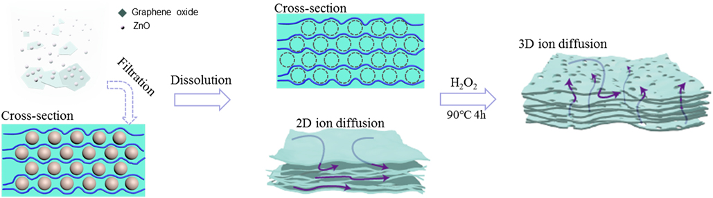
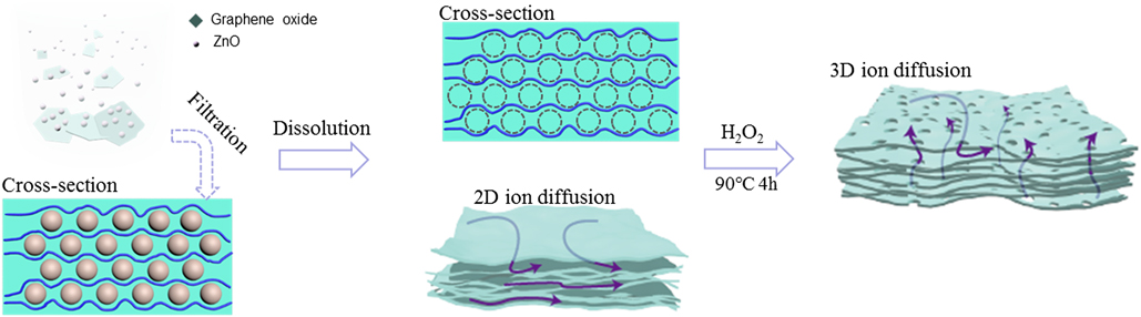
The facile synthesis procedure for MPGP can be briefly described in Fig. 1. Typically, the MPGP was synthesized in three steps: fabrication of the free-standing ZnO/GO paper by vacuum filtration of ultrasonicated mixed aqueous suspension containing GO and ZnO (100–500 nm), followed by removal of ZnO to generate 3D macroporous GO paper (denoted as PGP). Finally, controllable amounts of H2O2 aqueous solution with PGP were sealed in a Teflon-lined autoclave and heated to 120 °C for 4 h to yield the MPGP. The vacuum filtration process is reported to be suitable for assembling GO nanosheets into paper-like electrodes with high flexibility and good electrical conductivity.Reference Wan, Zhu, Yu, Sun, Wong and Liao24,Reference Ferrero, Sevilla and Fuertes25 However, the GO nanosheets tend to stack into graphite during vacuum filtration, which results in significant loss of surface area. The incorporation of spacer materials (metal oxide nanomaterials,Reference Tang, Li, Zhang, Zhu, Wang, Shi and Wei26 polystyrene nanospheres,Reference Wang, Yan, Liu, Chen, Shi, Zhang, Zhong and Zhang27,Reference Liu, Chen, Policastro, Becker and Zhu28 polymethyl methacrylate spheres,Reference Xu, Lin, Bi and Huang29 etc.) between graphene or GO nanosheets appears to be efficient to retain the high surface area of graphene or GO, especially after subsequent removal of spacer materials. Accordingly, the as-prepared 3D porous structure facilitates the electrolyte ions to transport at two-dimensional graphene planes. For graphene-based materials under highly compressed form or with a large packing density (>1.0 g/cm3), a large dead volume without accessing to the electrolytes will be resulted in. Therefore, the ion diffusion shortcuts between different graphene layers are highly required to make the electrolytes accessible to the entire compressed film. To this end, H2O2 was adopted to create a highly continuous network of micropores and mesopores for efficient ion transport in three dimensions. The carbon atoms around active defective sites of GO can be partially oxidized and etched into carbon vacancies, which further lead to nanopores.Reference Xu, Lin, Zhong, Huang, Weiss, Huang and Duan30 In detail, H2O2 generates higher OH˙ radical concentrations under hydrothermal condition. Subsequently, the OH˙ radical attacks the C–C sp 2 bonds of reduced GO and produces an OH adduct. Complete oxidation of carbon atoms to CO2 is further caused by continued attack of OH˙ radicals, finally leading to nanopores on the reduced GO layer. Thus the as-created mesopores could occur across the entire nanosheets due to the uniformly distributed defective carbon sites on the basal plane of GO.
Schematic illustration of the procedure to fabricate the 3D and multiscale porous GO paper through ZnO nanodisk templates and a subsequent H2O2 etching process.
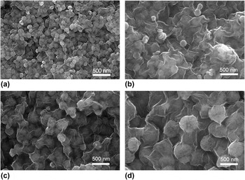
The template-directed approach has been reported to be an efficient way to prepare hierarchical porous carbon-based materials with a tunable pore structure. Generally, 3D graphene or GO with microstructure, mesostructure, or macrostructure is synthesized via utilizing various templates such as PS nanospheres, PMMA spheres, SiO2 nanospheres. Yet, these templates suffer from complicate synthesis and removal process (acid or base etching, calcinations), high cost, etc. In contrast, the unique features of ZnO nanomaterials such as easy control of scale and facile dissolubility even in weak acid or basic solution make ZnO an ideal template for construction of carbon-based materials with various nanostructures.Reference Zhao, Jiang and Xie31 ZnO nanodisks with different sizes ranging from 100 to 500 nm were prepared via a previously reported method.Reference Zhai, Xie, Zhao, Sun, Lu, Yu, Xu, Xiao and Tong32 Subsequently, ZnO nanodisks and GO suspension were mixed under controlled pH and vacuum filtrated for ZnO/GO paper films. During this process, the ZnO nanodisks were sandwiched in-between GO layers as “spacer” to form a composite that effectively prevents the GO layers from serious agglomeration in the vacuum filtration process. The morphologies of the intermediate ZnO/GO composites during fabrication of MPGP are shown in Fig. 2. For simplification, the sample of ZnO nanodisks with a diameter of 100 nm sandwiched by GO layers was denoted as ZnO-100/GO and so on. Clearly, the scanning electron microscopy (SEM) images of ZnO-100/GO, ZnO-180/GO, ZnO-250/GO, and ZnO-500/GO all demonstrate that ZnO nanodisks were uniformly wrapped by GO nanosheets, which can be attributed to the electrostatic and hydrophobic interactions between each other in aqueous solution. In detail, ZnO will hydrolyze in water solution to form hydroxide layers at the surface (≡Zn–OH) and then the hydroxide surface will be positively charged through reacting with H+ in water solution.Reference Degen and Kosec33 In contrast, the GO layers in water are negatively charged because of the ionization of carboxylate groups on the surface. Consequently, the negatively charged GO nanosheets bind electrostatically to the positively charged ZnO nanodisks. The spacer materials of ZnO-100/GO possess a smaller diameter of ∼100 nm than that of as-prepared ZnO-180/GO, ZnO-250/GO, and ZnO-500/GO samples and previously reported SiO2/GOReference Bae, Park, Kim, Lee, Kim and Seo34 and PMMA/GO,Reference Xu, Lin, Bi and Huang29 thus leading to a porous GO with a higher surface area after removal of spacer materials. Significantly, porous GO with a tunable surface area can be easily fabricated via the ZnO nanodisks with controllable size from 100 to 500 nm, indicating the feasibility of our method.
Magnified SEM images of (a) ZnO-100/GO, (b) ZnO-180/GO, (c) ZnO-250/GO, and (d) ZnO-500/GO composites, respectively.

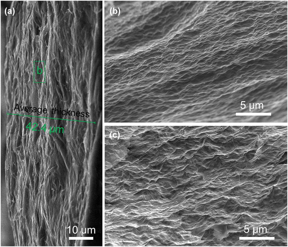
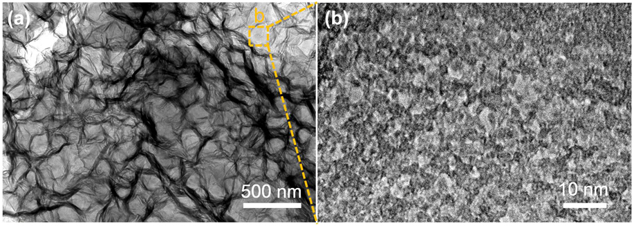
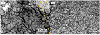
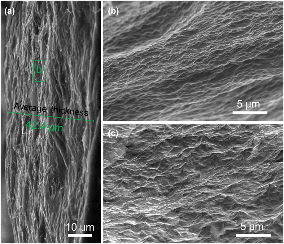
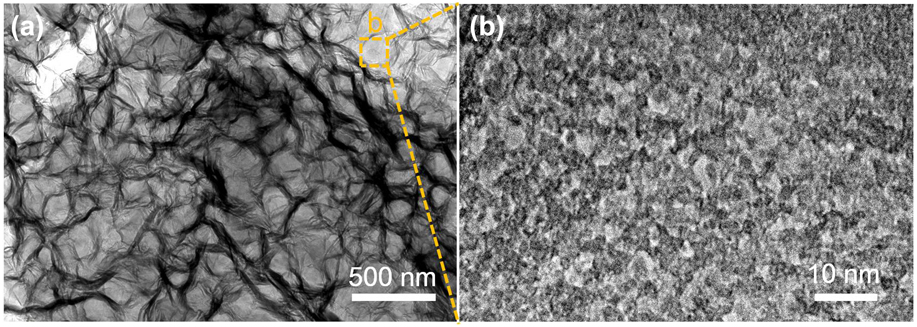
The selective removal of ZnO nanodisks in ZnO/GO composites leaves behind a porous GO paper (denoted as PGP). The macropore size of the PGP depends on the scale of the ZnO nanodisks as spacer materials, which controls the pore size in the range from 100 to 500 nm. The PGP with a macropore diameter of 100 nm was selected because of their potentially high-capacitive performance originated from a large surface area. Figure 3(a) presents the cross-sectional SEM image of the PGP with an average thickness of around 42.4 μm, which is substantially higher than most of the reported graphene or GO papers (<20 μm).Reference Ye, Zhou, Jia, Tang, Zhu and Wan35,Reference Chi, Zhang, Xi, Huang, Xiao, Wang and Liu36 The thickness of the electrode has appeared to be important for high-volumetric capacitance. More importantly, electrodes with larger thickness as well as high-volumetric capacitance are more preferred in design of energy storage devices (LIBs, SCs, etc.) due to the advantages as follows: (i) the ratio of active mass can be effectively enlarged, i.e., a high-energy density calculated based on the whole device can be achieved; (ii) less steps are needed to achieve the total energy capacity, thus decreasing the manufacturing cost. However, the ionic transport along the thickness direction in the electrodes is still problematic, especially for highly packed electrodes. Thus, electrodes with appropriate pore structures in more dimensions are highly required. Figure 3(b) shows the magnified SEM image of the PGP. The porous structure with a pore diameter of ∼100 nm retains well after the removal of the ZnO template, which can be ascribed to the interconnected feature of GO layer walls in 3D structure. Moreover, the porous structure throughout the entire thick GO paper again confirms the important role of ZnO nanodisks as spacers in preventing the restack of GO layers. The PGP was further treated by H2O2 (for details, see Sec. II) to generate micropores and mesopores. The SEM image of MPGP in Fig. 3(c) demonstrates that the as-assembled 3D porous GO structure did not collapse and no obvious morphology change was observed on the GO layer. Transmission electron microscopy (TEM) was performed to further investigate the microstructure and nanostructure of the MPGP. Figure 4(a) shows the TEM image of the MPGP, presenting the well-defined porous structure with interconnected and overlapped pores. Moreover, no traces of the ZnO “spacer” in the MPGP can be observed, which indicates the complete removal of ZnO “spacers”. The macropores are determined to be about 100 nm, which is in well accordance with the diameter of the ZnO nanodisks that confirmed by SEM results [Fig. 2(a)]. Furthermore, the high-resolution TEM image of the selected area (marked by yellow dashed box) in Fig. 4(b) presents abundant uniformly distributed mesopores with a diameter of 2–3 nm on the GO layer, indicating the carbon atoms of GO were etched efficiently by H2O2. The as-designed MPGP with hierarchical pores to facilitate efficient ionic transport would be desirable in SCs.
(a) Low-magnified and (b) high-magnified cross-sectional SEM images of the PGP. (c) High-magnified cross-sectional SEM image of the MPGP.
TEM images at different magnifications of MPGP.
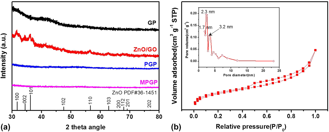
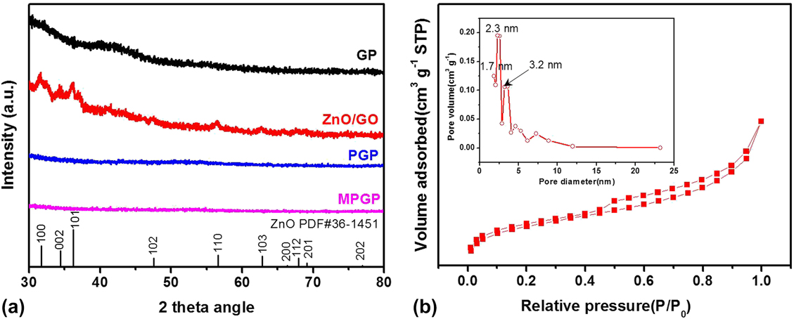
X-ray diffraction was used to further confirm the complete removal of ZnO nanodisks in the MPGP and PGP. The XRD pattern of the GO paper (denoted as GP) was added for comparison. As shown in the XRD pattern of ZnO-GO in Fig. 5(a), peaks located at 31.8°, 34.4°, 36.3°, 47.5°, and 56.6° can be well indexed to the wurtzite structure [JCPDS # 36-1451; a = b = 3.249 Å, c = 5.206 Å, space group: P63mc(186)]. After the etching process, no peaks ascribed to ZnO can be observed in PGP and MPGP samples, confirming the full removal of ZnO nanodisks from the 3D composites. No characteristic peaks ascribed to GO can be observed in the four XRD patterns due to the poor crystallinity of the as-prepared GO film. We carried out the BET measurements to further characterize the detailed porous structure of the MPGP. Figure 5(b) shows the nitrogen adsorption–desorption isotherm of the MPGP. Obviously, the isotherm of the MPGP presents an increase in the amount of N2 absorbed at both low relative pressure (P/P 0 < 0.1) and high-relative pressure (P/P 0 > 0.9), indicating the existence of amounts of micropores and macropores, respectively.Reference Zhao, Lai, Lyu, Jiang, Xie, Wang, Wu, Yang, Jin, Ma, Liu and Hu37 In addition, the presence of mesopores can be suggested by the hysteresis located between P/P 0 = 0.4 and P/P 0 = 1.0.Reference Wang, Wang, Lu, Ling, Yu, Zhai, Tong and Li38 The inset of Fig. 5(b) shows the pore size distribution of MPGP calculated based on the absorption–desorption isotherm using the Barrett–Joyner–Halenda (BJH) method. A large quantity of pores with diameter from 1.7 to 3.2 nm were available for MPGP, again indicating the occurrence of micropores and mesopores. The high micropore and mesopore volume can be attributed to the aforementioned H2O2 etching process. Moreover, a significant high-BET surface area is determined to be 960 m2/g, which is considerably higher than some reported carbon materials at a similar thickness level.Reference Shu, Wang, Li, Zhao, Yang, Liu and Wallace39
(a) XRD pattern of GO, ZnO/GO, PGP, and MPGP, respectively. (b) Nitrogen absorption–desorption isotherms of the MPGP collected at liquid nitrogen temperature (77 K). The inset of (b) is the pore size distribution calculated based on the absorption–desorption isotherm using the Barrett–Joyner–Halenda (BJH) method (pore size ranges between 1 and 25 nm).
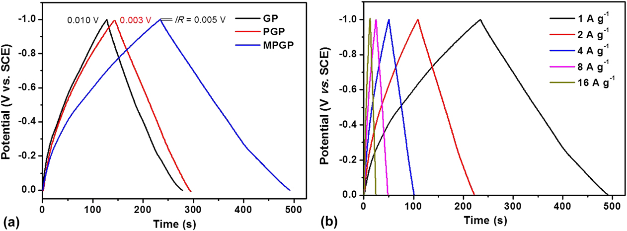
To evaluate the enhanced capacitive performance of the multiscale porous GO paper, the electrochemical performance was determined in a three-electrode system with a SCE as the reference electrode, a Pt electrode as the counter electrode, and 3 M KOH as electrolytes. The electrochemical performance of the GP and PGP was also characterized for comparison. Figure 6(a) compares the GCD profiles of MPGP, PGP and GP electrodes collected at a current density of 1 A/g. All the three curves exhibited a symmetrical triangular shape, indicating the good EDL behavior. Significantly, the charge/discharge curve of the MPGP is more symmetric and substantially prolonged as compared to that of the GP and PGP. Notably, the MPGP electrode possesses a slightly larger IR drop (a voltage drop that appears at electrode with resistance during a current flow) of 0.005 V than that of the PGP (0.003 V). It shows that the oxidation during H2O2 treatment has a minor effect on the electrical conductivity of the MPGP. Besides, the IR drop of the MPGP is smaller than the value of GP (0.01 V), revealing the good electrical conductivity of MPGP. The Cs (specific capacitance) value of the MPGP at 1 A/g is determined to be 246 F/g (307.5 F/cm3), which is substantially larger than that of the PGP (147 F/g; 183.8 F/cm3) and GP (139 F/g; 173.8 F/cm3). Additionally, the value is also larger than or comparable to that of the previously reported graphene or GO paper electrodes at the same current density.Reference Ferrero, Sevilla and Fuertes25,Reference Ye, Zhu, Tang, Wan and Jia40,Reference Shao, Tang, Lin, Li, Qin, Yuan and Qin41
(a) GCD curves of MPGP, PGP, and GP at a current density of 1 A/g. (b) GCD curves of the MPGP collected at different current densities from 1 to 16 A/g.
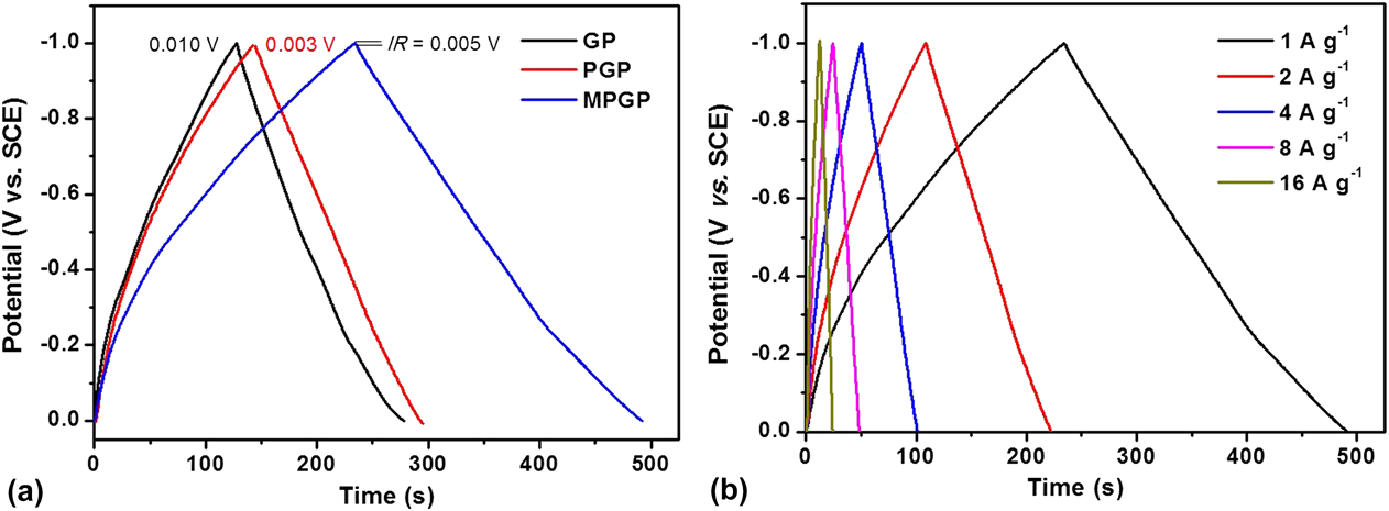
The micropores and mesopores of the MPGP provide amounts of active sites for charge accumulation, which further boost the specific capacitance of the MPGP. Figure 6(b) shows the GCD curves of the MPGP collected at current densities ranging from 1 to 16 A/g. The charge curves at different current densities are relatively symmetric to their corresponding discharge curves, again confirming their good capacitive behavior. The specific capacitance slowly decreased from 246 to 192 F/g as the current density increased from 1 to 16 A/g. An outstanding retention of 78% was achieved due to the multiscale porous structure, which provides effective pathways for fast ion transfer, enabling the good rate capability.
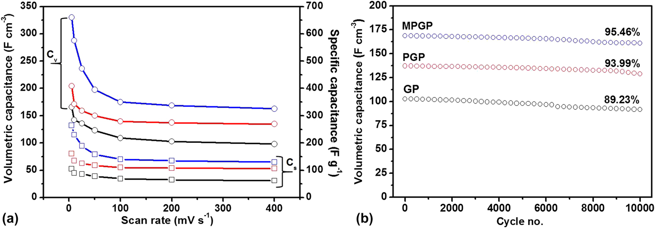
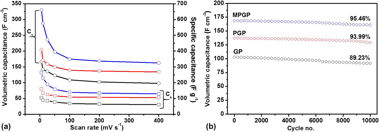
Figure 7(a) displays the specific capacitance of the MPGP, PGP, and GP as a function of scan rates. The values were extracted from their corresponding CV curves. As expected, the MPGP outperforms PGP and GP in specific capacitance at all scan rates ranging from 5 to 400 mV/s. In specific, the MPGP delivers an attractive capacitance of 264 F/g (330 F/cm3; 5.33 mg/cm2) at 5 mV/s, which is much larger than 161 F/g (204.5 F/cm3; 5.4 mg/cm2) and 105 F/g (165.7 F/cm3; 3.9 mg/cm2) for PGP and GP, respectively, at the same scan rate. The enhancement in capacitance is in well accordance with the aforementioned results from charge/discharge curves and can be ascribed to the increased active sites raised from mesopores. Moreover, the values are also higher than that of previously reported graphene or GO paper electrodes, such as the graphene paper (80 F/g; 2.4 mg/cm2),Reference Ye, Zhu, Tang, Wan and Jia40 holey graphene paper (50 F/g; 3.0 mg/cm2),Reference Ferrero, Sevilla and Fuertes25 and CNT (carbon nanotube)-spaced graphene aerogels (245 F/g).Reference Shao, Tang, Lin, Li, Qin, Yuan and Qin41 Notably, the thickness of the paper-like electrode is a major factor that should be considered when comparing with the reported electrodes. A thicker electrode with high packing density is critical for the application of SCs. Due to the high packing density of 1.25 g/cm3, the MPGP achieves a substantially high-volumetric capacitance of 327 F/cm3 at 5 mV/s, enabling it as highly promising as SC electrodes with high-volumetric performance for applications with limited space, e.g., miniature electronic devices. In addition, the MPGP exhibits a more stable cycling life with a capacitance retention of ∼96% after 10,000 CV cycles at 400 mV/s in the 3 M KOH electrolyte, while that of the PGP and GP is around 94% and 89%, respectively. Notably, the three samples were characterized directly without any binders, which further leads to exfoliation and consequent capacitance degradation during cycling test. The multiscale porous structure of the MPGP is suitable for alleviating the capacitance degradation during the repeated charge/discharge process. The above results confirm that the enhanced capacitive behavior can be attributed to the following aspects: (i) the outstanding electric conductivity of the GO layer; (ii) the boosted surface area and highly efficient ion transport originated from the multiscale porous structure. The advantages also unambiguously proved that the MPGP is a promising scaffold for pseudocapacitive materials to achieve high-volumetric capacitance at high rates.
(a) Comparison of specific and volumetric capacitances as a function of different scan rates for MPGP, PGP and GP. (b) Cycling stability of MPGP, PGP, and GP collected at a scan rate of 200 mV/s for 10,000 cycles.
Increasing the cell voltage of SCs is proved to be more efficient to boost the energy density as compared to the enlargement of capacitance.Reference Zhai, Wan, Sun, Chen, Sun, Xia and Xia1 ASCs in aqueous electrolytes can achieve a voltage up to 2.6 V by making full use of potential windows of two different electrodes. In this work, we evaluated the capacitive performance of the as-prepared MPGP at the device level through constructing an ASC device. The ASC device was assembled based on MnO2 on the MPGP (denoted as MnO2/MPGP) as the cathode and MPGP as the anode (for details, see Sec. II). Manganese oxides (MnO2) have attracted intensive interest as a promising pseudocapacitive material in SCs due to its large theoretical capacity (1370 F/g), abundant and environmentally friendly nature, etc.Reference Zhai, Xie, Yu, Fang, Liang, Lu and Tong42 We incorporated MnO2 with the MPGP to further boost the pseudocapacitive performance of MnO2. The MnO2/MPGP was synthesized via an electrochemical deposition method (for details, see Sec. II). Figure S1 shows the SEM images of MnO2 nanosheets on the MPGP, presenting that the MnO2 nanosheet-assembled nanoparticles with a diameter of less than 300 nm are uniformly distributed on the MPGP scaffold. The X-ray photoelectron spectroscopy (XPS) spectra including Mn 3s [Fig. S2(a)] and Mn 2p [Fig. S2(b)] core-level spectra were performed to confirm the composition of MnO2, which are consistent with previous reports.Reference Zhai, Xie, Yu, Fang, Liang, Lu and Tong42,Reference Ma, Shao, Fan, Wang, Song and Shen43 CV curves of the MnO2/MPGP electrode were collected at different scan rates ranging from 10 to 100 mV/s in the 0.5 M Na2SO4 electrolyte. As shown in Fig. S3(a), characteristic quasirectangular shapes can be observed for the MnO2/MPGP electrode at all the scan rates in a potential window of 0–1.0 V versus SCE, indicating the typical pseudocapacitive behavior of MnO2. Significantly, a high-volumetric capacitance of 180.6 F/cm3 was achieved at a scan rate of 5 mV/s [Fig. S3(b)]. Moreover, it retained 91.7 F/cm3 at 100 mV/s, with 50.7% retention of initial capacitance at 5 mV/s, which is higher or comparable to previously reported MnO2-based composites.Reference Ma, Shao, Fan, Wang, Song and Shen43,Reference Wang, Yang, Liu, Zeng, Li, Huang and Hu44
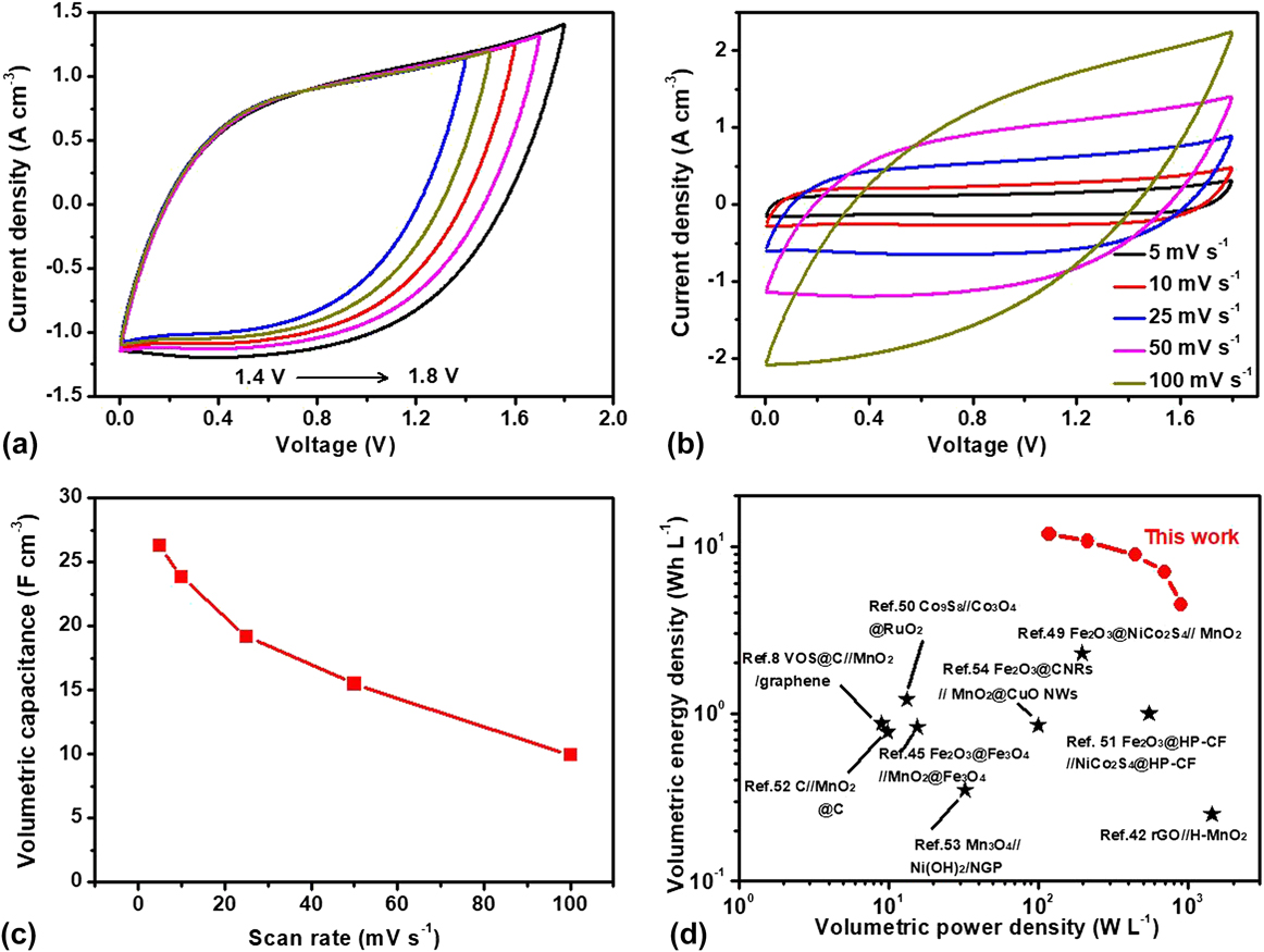
For performance maximization of the as-assembled ASC device, we used the charge balance theory (for details, see Sec. II) to balance the charge between the positive and negative electrodes. Figure S4 shows the CV curves of the MPGP and MnO2/MPGP electrode collected at a scan rate of 100 mV/s. The mass ratio (MnO2/MPGP:MPGP) for the ASC device is calculated to be about 0.86:1. According to the CV studies in Fig. S4, the operating voltage of device is expected to be extended to 1.8 V. Figure 8(a) demonstrates the CV curves of the MnO2/MPGP//MPGP ASC device collected at different voltage windows at 100 mV/s. As expected, the as-assembled MnO2/MPGP//MPGP device is electrochemically stable in the voltage window of 0–1.8 V. The GCD measurement (Fig. S5) also confirms the stable voltage window for the ASC device. CV studies of the MnO2/MPGP//MPGP ASC device collected at various scan rates are shown in Fig. 8(b) to further illustrate its capacitive performance. CV curves at all scan rates present a rectangular-like shape and remain unchanged even when the scan rate is increased to 100 mV/s, confirming the ideal capacitive behavior and fast responsive properties of the MnO2/MPGP//MPGP ASC device. Figure 8(c) shows the volumetric capacitance of the MnO2/MPGP//MPGP as a function of scan rates. The device achieved 26.3 F/cm3 at 5 mV/s, which is substantially higher than those recently reported values for MnO2-based ASC devices, such as the Fe3O4@Fe2O3//Fe3O4@MnO2 ASC device (1.49 F/cm3, 1.25 mA/cm2),Reference Tang, Jia, Zhai and Xia45 MnO2/CNT/nylon fiber SC (3.8 F/cm3, 10 mV/s),Reference Choi, Kim, Sim, Lee, Choi, Kim, Lepró, Spinks, Baughman and Kim46 CNT spring fiber SC (18.12 F/cm3, 10 mV/s),Reference Zhang, Bai, Cheng, Ren, Weng, Chen, Fang, Zhang and Peng47 and MnO2/Au/MnO2 nanospike SSC (symmetric supercapacitor) device (20.3 F/cm3, 0.2 mA/cm2).Reference Gao, Jin, Lin, Li, Tavakoli, Leung, Tang, Zhou, Wa Chan and Fan48 Moreover, a good rate capability of 36.5% retention of initial capacitance was delivered as the scan rates increased from 5 to 100 mV/s. Notably, the capability was achieved in a device with both the thick positive electrode and thick negative electrode. Thus, the rate capability is quite competitive with previously reported ASC devices. In addition, the charge–discharge curves of the MnO2/MPGP//MPGP device (Fig. S5) show the triangular shapes at different current densities, again confirming the outstanding electrochemical properties of the as-assembled ASC device. As one of the most important parameters for high-performance SCs, the long-term cycling stability of the MnO2/MPGP//MPGP ASC device was evaluated at a scan rate of 50 mV/s for 5000 cycles. As shown in Fig. S6, the ASC device exhibits an outstanding electrochemical stability, with a capacitance retention of 92.4% of the initial capacitance values after 5000 cycles. The good cycling performance of the as-assembled ASC is comparable with recently reported high-performance ASC devices.Reference Zhang, Bai, Cheng, Ren, Weng, Chen, Fang, Zhang and Peng47,Reference Gao, Jin, Lin, Li, Tavakoli, Leung, Tang, Zhou, Wa Chan and Fan48
(a) CV curves of the MPGP//MnO2/MPGP ASC device collected at 50 mV/s in different voltage windows. (b) CV curves of the MPGP//MnO2/MPGP ASC device collected at different scan rates. (c) Volumetric capacitance of MPGP//MnO2/MPGP as a function of scan rates. (d) The Ragone plot of MPGP//MnO2/MPGP.
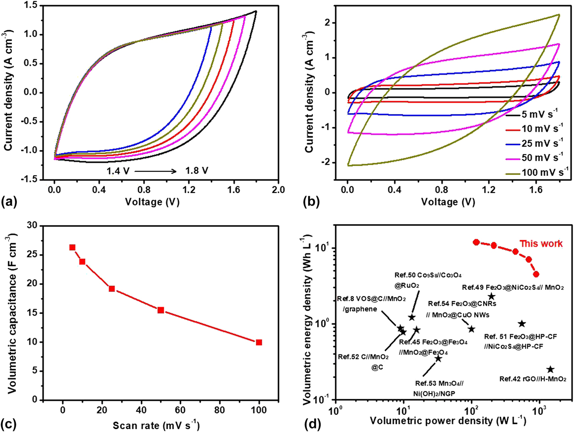
The energy density (E) and average power density (P) are also key parameters to determine the electrochemical performance of SCs (for detailed calculations, see Sec. II). Figure 8(d) illustrates the Ragone plots calculated based on the CV curves in Fig. 8(b). The values reported for other MnO2-based ASC devices have also been demonstrated for better comparison. The as-assembled MnO2/MPGP//MPGP ASC device exhibits a volumetric energy density of 11.8 W h/L (based on the whole volume of the device) at a scan rate of 5 mV/s, and this retains 4.47 W h/L at 100 mV/s, confirming the high-volumetric performance and outstanding rate capability of the as-assembled ASC device. The volumetric energy density values are considerably higher than those of recently reported MnO2-based ASC devices, such as Fe2O3@NiCo2S4//MnO2 (2.3 W h/L),Reference Jia, Zhu, Sun, Zhai and Xia49 Co9S8//Co3O4@RuO2 (1.2 W h/L),Reference Xu, Wang, Wang, Xiang, Liang, Chen and Shen50 Fe2O3@HP-CF//NiCo2S4@HP-CF (1.0 W h/L),Reference Chen, Xu, Zhou, Zhao and Wong51 VOS@C//MnO2/graphene (0.88 W h/L),Reference Zhai, Lu, Ling, Yu, Wang, Liu, Liang, Tong and Li8 and C//MnO2@C (0.77 W h/L).Reference Zhong, Shi, Liu, Huang, Cheng, Cheng, Li, Liao and Tang52 Additionally, a maximum average power density of 894.6 W/L was achieved at a current density of 100 mV/s, which is also much higher than recently reported ASCs.Reference Zhai, Xie, Yu, Fang, Liang, Lu and Tong42,Reference Tang, Jia, Zhai and Xia45,Reference Feng, Ye, Lu, Tong and Li53,Reference Yu, Moore, Calderon, Zhai and Thomas54 The results above unambiguously proved that the MPGP is very promising as a high-performance electrode as well as a good support for pseudocapacitive materials, opening up new opportunities for constructing advanced SCs with high-electrochemical performance per volume.
IV. CONCLUSION
In summary, we have demonstrated a template-assisted and chemical method to synthesize a highly packed GO-based electrode with a multiscale porous structure, which contains 3D macropores with a diameter of ∼100 nm and mesopores with a diameter of 2–3 nm. Significantly, the MPGP electrode delivers an outstanding specific capacitance of 262 F/g and a volumetric capacitance of 327 F/cm3 at a current density of 1 A/g. Moreover, the rate capability of the MPGP reaches 78% retention from 1 to 16 A/g. The presence of multiscale porous structure is critical for the high-volumetric capacitance and rate capability, thus making it highly attractive to practical applications. The as-prepared hierarchically porous GO paper is also able to serve as an excellent scaffold for pseudocapacitive materials with poor conductivity and ionic diffusivity. A high-performance MnO2 coated on the MPGP was prepared as the positive electrode and assembled with the MPGP into an ASC, which achieved a high-volumetric energy density of 11.8 W h/L at 118.2 W/L, confirming that the high-performance thick electrodes are efficient for advanced SCs.
Supplementary Material
To view supplementary material for this article, please visit https://doi.org/10.1557/jmr.2017.449.
ACKNOWLEDGMENTS
Prof. H.X. thanks the support of the National Natural Science Foundation of China (Nos. 51301064 and 51572129), International S&T Cooperation Program of China (No. 2016YFE0111500), Natural Science Foundation of Jiangsu Province (No. BK20170036), QingLan Project of Jiangsu Province, A Project Funded by the Priority Academic Program Development of Jiangsu Higher Education Institutions (PAPD), the Fundamental Research Funds for the Central Universities (Nos. 30915011204 and 30916011352), and Russian Foundation for Basic Research (No. 16-29-06439). T.Z. acknowledges the support of the Natural Science Foundation of China (51602158), Natural Science Foundation of Jiangsu Province (BK20160835), and Fundamental Research Funds for the Central Universities (No. 30916011352) and the support of MOE Key Laboratory of Bioinorganic and Synthetic Chemistry (Sun Yat-Sen University, Guangzhou, China).