Introduction
Today's microscale regime demands low profile wideband antenna with high gain and better efficiency in communication industries such as microwave image processing, radar communication, satellite, and wireless personal communication. Different wideband approaches have been stated to fulfill the aforementioned required characteristics from a single antenna. Bandwidth enhancement was achieved using slot and stub loading technique [Reference Lacik, Mikulasek and Raida1, Reference Dwivedi and Kommuri2]. Further to achieve ultra-wideband (UWB) range, different geometries such as circular ring, annular ring, and hexagonal shapes have been investigated and proposed [Reference De and Sarkar3, Reference Liu, Cheung, Azim and Islam4]. Fractal structures were well explored to achieve dual-band, wideband, and UWB antennas [Reference Sawant and Suthikshn Kumar5–Reference Ali, Azim and Islam7]. On the contrary, low gain and unstable radiation patterns of these techniques confine its applicability. A compact Vivaldi antenna was reported for UWB application with a stable radiation pattern [Reference Pandey, Verma and Meshram8], but the complex design and large dimension was the limitation. Electromagnetic band-gap (EBG) structure is also examined for the high gain solution in wideband antenna [Reference Bao, Wen, Li, Jiang and Li9–Reference Park, Kim, Jung, Lee, Cho and Lee11]. The design complexity of metallic via and large ground limits EBG usage for low profile application. Low complexity corporate-feed structure is also proposed for gain enhancement [Reference Farran, Boscolo, Locatelli, Capobianco, Midrio, Ferrari and Modotto12]; however, this solution suffers from complex geometry. Fractional bandwidth of 30% was achieved and occupies a large area to provide feed network. Later different types of frequency-selective surfaces (FSS), the combination of FSS with PBG and the combination of metamaterial and FSS structure, were presented for the improvement of gain and radiation property [Reference Nejati, RA and Geran13, Reference Erdemli, Sertel, RA and JL14]. Gain improvement achieved was 32% (2 dBi) using FSS and PBG technique compared to a simple form of patch antenna [Reference Nejati, RA and Geran13]. Radiation property was improved in 3:1 ratio for dipole array [Reference Erdemli, Sertel, RA and JL14]. Equivalent circuit was reported for FSS-based metamaterial absorber in [Reference Ghosh and Srivastava15]. The effect of slot on patch and filter insertion near feed is studied and reported for the improvement of realized gain in [Reference Tang, Shi and RW16]. Meta-material loaded structures were also reported for gain enhancement of planar antennas [Reference Vaid and Mittal17, Reference Gao, Cai and Zhu18]. On the contrary, these techniques require large ground area, low bandwidth, and demand a solution of low profile structure. A detailed analysis of the UWB high gain antenna with radiation pattern stability is seldom discussed. Recent research shows that the gain of a conventional antenna can be enhanced using artificial magnetic conductor (AMC) ground but it is only applicable for dual-band, multiband, and wideband applications [Reference Kim, Yang and Elsherbeni19–Reference Dewan, MKA, MR, MFM, NA, NA and Kamardin23]. Dual-band rejection using CSRR is also reported in UWB application [Reference Dwivedi, Usha Kiran, Gnanagurunathan, Sangeetha and Kiran24]. Cross-slot AMC is recently proposed and gain bandwidth enhancement of 48% is reported [Reference Pandit and Harish25]. AMC was studied and implemented for 5G application in [Reference Kassim, Rahim, Malek, Ahmad, Jamaluddin, Jusho, Mohsin, Yahya, Wee, Adam, Rani, Saini, Singh, Tariq Beg and Sahambi26]. It was established that loop-based AMC provides better angular stability and compact structure as shown in [Reference De cos and Las heras22], and triple-band absorber was proposed and polarization independency concept with equivalent circuit was reported in [Reference Bhattacharyyaa, Ghosh and Srivastava27]. It was established that a wideband AMC design is required to cover the entire UWB region. It should also provide high gain with low profile structure for desired application.
In this research work, an effort is made to design an UWB low profile high gain antenna. A novel low profile high gain antenna is proposed using wideband artificial magnetic conductor (WB-AMC). The design of UWB antenna and evolution stages using stub loading with a curved ground plane approach is elaborated in “UWB antenna design” section. The proposed UWB antenna has a compact volumetric size of (0.4λ 0 × 0.4λ 0 × 0.13λ 0) mm3. Here (λ 0) is the lowest free space wavelength at 3.1 GHz. Further low profile WB-AMC design and optimization are discussed using loop-based WB-AMC in “WB-AMC” section for gain enhancement. “Result and discussion” section elaborates the results and discussion by validating the simulated and measured data. Time domain analysis is also carried out for a face-to-face configuration and presented briefly. Finally, the conclusion of the proposed work is discussed in “Conclusion” section. The novelty of the proposed antenna is the improvement in gain without deteriorating the antenna performance. Profile reduction of 50% is achieved compared to perfect electric conductor (PEC) profile. Moreover, the qualitative comparison of the reported antennas with the proposed antenna is presented. It is clearly seen that the proposed UWB antenna has better performance in all aspects and outperforms the art of work for UWB application.
UWB antenna design
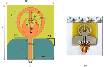
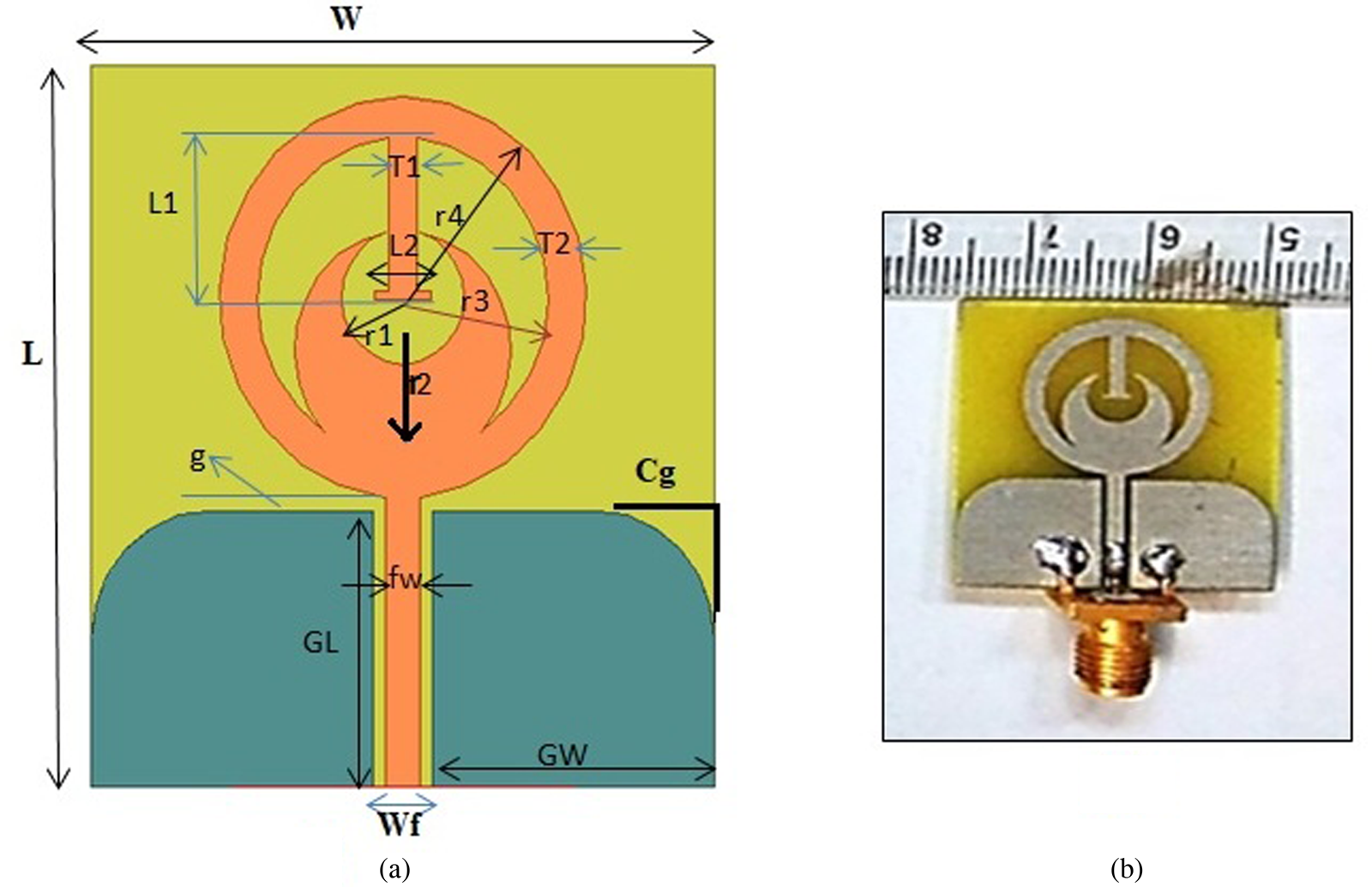
The proposed UWB antenna has an annular ring radiating structure loaded with a T- and crescent-shaped stub. It is fed with a 50 Ω CPW line with gap/signal/gap (0.3/2.5/0.3) mm. The suggested antenna is fabricated on an FR-4 substrate of ɛ r = 4.4 and a thickness of 1.6 mm. Primary design equation to calculate the fundamental resonance frequency and annular ring dimension is calculated using [Reference Lacik, Mikulasek and Raida1, Reference Dwivedi and Kommuri2] and it is presented in equations (1) and (2).


Here “n” is chosen as 1 for exciting fundamental mode. Effective permittivity of the medium is denoted as ɛ eff. Effective design parameters of the proposed antenna (L1, L2, T1, T2, r1, r2, r3, and r4) are vertical length, horizontal length, thickness of the T-shaped stub, thickness of annular ring, and all four radii of the crescent shape and annular structure, respectively. Other design parameters (GW, GL, fw, Wf, and g) are ground width and length of side, feed width, gap combined with feed, and gap between ground and patch, respectively. The presented antenna has an overall size of (0.29λ 0 × 0.27λ 0 × 0.016λ 0) mm3. The proposed antenna with a crescent- and T-shaped open-ended stub for UWB application is shown in Fig. 1 and the optimized dimensions of the proposed antenna are given in Table 1.
(a) Proposed UWB antenna. (b) Fabricated UWB antenna.
Dimension of the proposed UWB antenna

Evolution stage of UWB antenna
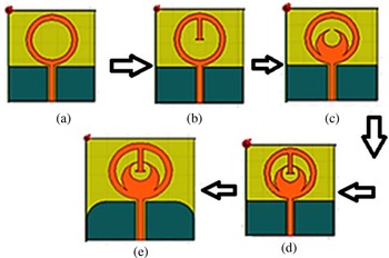
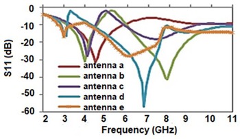
An important parameter of UWB antenna is the inclusion of stub to create extra resonance by preserving the compactness. The structure of the fundamental antenna is depicted in Fig. 2(a) and it resonates at 5 GHz covering the frequency band from 3.2 to 5.8 GHz with 57% fractional bandwidth. The wideband antenna is optimized for maximum impedance bandwidth and better radiation patterns simultaneously. To mitigate the mismatch and achieve UWB, the curved ground approach is followed and optimized further to provide better impedance matching for the entire band of interest. The step by step modified design flow for the proposed CPW fed UWB annular ring antenna is presented in Figs 2(a)–2(e). To achieve wide operational bandwidth, the T- and crescent-shaped open-ended stub is loaded inside the ring radiator. As a result of this modification, dual-band resonance occurred at 7 and 8.2 GHz, respectively. Dimensions of the T-shaped stub (L1, L2, and T1) have been optimized further to cover the lower band of UWB while keeping all other structural parameters constant. It is observed that increasing the length of the stub L1 and simultaneously decreasing its width T1 shifts the resonance to the lower side with improved return loss. The fractional bandwidth is increased from 57 to 76% in this case. Antenna evolutions can be seen after the incorporation of stubs as indicated in Figs 2(b)–2(d).
Evolution stage of CPW fed UWB antenna.

Further to cover the UWB range, the ground plane is tailored into a curve shape (both side of the corner) as depicted in Fig. 2(e). It can be observed that return loss performance improved near 6.8 GHz (Antenna-D) due to stub insertion inside the annular ring antenna. This in turns deteriorated the return loss near 3.5 GHz. Knowing the fact that curve transition provides gradual shift in impedance and smooth surface current flow near the bends instead of sharp bend, we have optimized the curved ground such that it offers better surface current flow and gradual impedance transformation near the lower band of UWB. We have performed the parametric analysis to see the effect of curved ground plane while keeping other parameters constant. It was observed that altering the corner of ground plane affects the return loss near the lower band of UWB due to smooth transition at the corners. Further optimizing the CPW ground plane and increasing the curve length Cg improves the return loss near the lower band of UWB. Finally, fractional bandwidth of 97.18% from 3.7 to 10.6 GHz is attained with center frequency at 7.1 GHz. Improvement was also observed near 3.5 GHz frequency due to curved ground approach. The return loss variations for the evolution stages are depicted in Fig. 3 for different evolution stages of the suggested antenna.
Return loss variation for antenna evolution stage.

WB-AMC
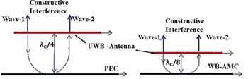
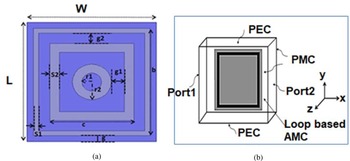
This section explains the design and analysis of fundamental square unit-cell AMC for bandwidth enhancement. The AMC is designed to reflect the incident wave that is in phase with the direct wave radiated by the antenna with half of the distance of PEC ground as shown in Fig. 4. The frequency deviation for the resonances, stable bandwidth, and gap effect for different possible structures is also verified through extensive simulation. The optimized values of the loops for the highest bandwidth are considered because once the substrate material and the shape of the unit cell are fixed, wide reflection phase bandwidth can be obtained by varying loop width of unit cells [Reference Bhattacharyyaa, Ghosh and Srivastava27].
Comparison of profile reduction of proposed antenna using WB-AMC ground.

WB-AMC design
Initially, a square patch of 18 × 18 mm2 is taken with a PEC of 20 × 20 mm2 on the back side to provide resonance at 7.0 GHz. The WB-AMC investigated in this work contains multi-loop structure (two outer square loops and one circular loop). To provide maximum reflection, the reflection coefficient magnitude and phase should be 0.9 < Г and +90° < θ < −90°, respectively. It is proven through the research that AMC designed using loop-based structures required compact area as compared to the conventional patch [Reference De cos and Las heras22]. Knowing the fact that reducing the overall capacitance and increasing the inductance of the structure leads to the bandwidth enhancement [Reference Gao, Cai and Zhu18]; initially geometry of the conventional square patch was designed and further modified into square loop to maximize the offered inductance. The resonance angular frequency of AMC, and magnitude and phase of the AMC ground plane are calculated using equations (3)–(5), from [Reference Kim, Yang and Elsherbeni19]. When the denominator in equation (4) is set to zero, the surface offers nearly infinite impedance and works as a perfect reflector.


AMC demonstrates in phase characteristics like perfect magnetic conductor for certain bandwidth, as proven in [Reference Erdemli, Sertel, RA and JL14]. Bandwidth for AMC is taken from −90° (lower frequency) to +90° (upper frequency) with 0° phase shift at resonance frequency (fc), here the resonance frequency of AMC is 7.0 GHz. The values of effective wavelength (λ eff) and effective permittivity (ɛ reff) are calculated from the resonance frequency. The initial patch size is L p and it is calculated from equation (6).


L and C are total inductance and capacitance offered by WB-AMC and H is denoted as the thickness of the substrate. Equations (6)–(8) are used to calculate the parameter and are rewritten from [Reference De cos and Las heras22].
Evolution stage of WB-AMC
The proposed WB-AMC is presented in Fig. 5(a) and the simulation set up in HFSS tool is presented in Fig. 5(b). Design parameters of the proposed WB-AMC are presented in Table 2.
(a) Proposed WB-AMC structure. (b) Simulation set up in HFSS tool.

Design parameters of WB-AMC with their dimension

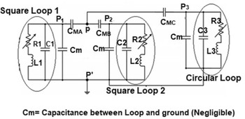
Equivalent circuit of the proposed WB-AMC is shown in Fig. 6. The WB-AMC design parameters L1, C1, L2, C2, L3, and C3 are the corresponding inductance and capacitance for the outer square loop1 of width S1, square loop 2 of width S2, and circular loop of width (r2–r1), respectively. CMA, CMB, and CMC are the mutual capacitance between the respective loops. Cm is the capacitance between loops and ground plane. Calculated values of the parameters are presented in Table 3.
Equivalent circuit of proposed loop-based WB-AMC.

WB-AMC parameter calculated values using formula

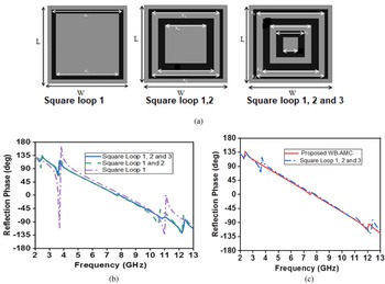
Evolution stage of the proposed WB-AMC is presented in Fig. 7(a). It is noticed from Fig. 7(b) that the reflection phase bandwidth of the multi-loop AMC has increased proportionally for the dual-loop and triple-loop combination. Optimization has been carried out further to achieve the desired wideband characteristics (+90° to −90°) in terms of reflection phase bandwidth. Reflection phase response was poor at higher frequency band for three square loops AMC. Further, inner square loop was modified into circular loop and it was observed from Fig. 7(c) that the proposed square and circular loop WB-AMC structure provided bandwidth from 3.8 to 10.8 GHz and selected for further analysis to enhance the gain of the proposed UWB antenna.
(a) Evolution stage of loop-based WB-AMC. (b) Reflection phase comparison for loop-based WB-AMC. (c) Reflection phase variation of proposed WB-AMC and square loops (1, 2, and 3).

The WB-AMC ground is formed by [2 × 2] unit cells. This dimension is picked to provide optimal performance with low profile, compact structure, and high gain. WB-AMC is spaced (λ c/8) at 7 GHz underneath the UWB antenna. This spacing has been selected for achieving an optimal −10 dB reflection coefficient and high gain performance by undertaking the analysis on the spacing between the UWB antenna and the WB-AMC. Additional verification of the electric field intensity for the WB-AMC structure at varying space is also observed and it was seen that for (λ c/4 = 10.5 mm) spacing, it produces a maximum electric field with constructive interference. This WB-AMC configuration reduces the distance between the antenna and ground plane of about 50% compared to the PEC ground plane and provides a low profile high gain solution.
Result and discussion
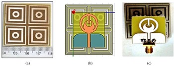
Detailed result analysis of the proposed high gain UWB antenna is presented in this section based on return loss variation, radiation pattern and gain, efficiency, and group delay performance. Fabricated WB-AMC and low profile UWB antenna is presented in Figs 8(a)–8(c). The subsequent subsection reveals the results based on significant parameter discussions such as return loss, gain, and group delay.
(a) Fabricated WB-AMC. (b) Simulation profile. (c) Fabricated UWB antenna.

Return loss analysis
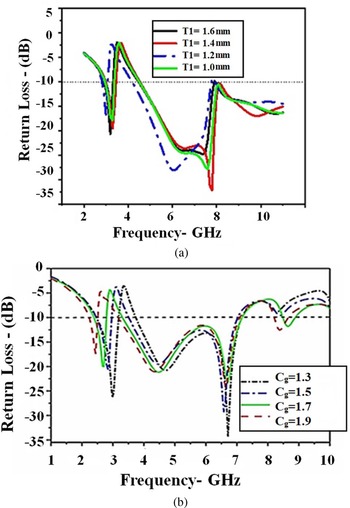
Return loss is defined as the logarithmic value of reflection coefficient (S11). It was tuned and optimized through stub and curved ground to get the desired output. Figures 9(a) and 9(b) show the effect of stub parameter (T1) and curved ground parameter (Cg). It was observed that return loss was improved while increasing the stub width from 1.0 to 1.2 and started reducing the bandwidth after 1.2 mm. In the same manner, bandwidth was improved for curved ground (Cg) from 1.3 to 1.7 mm and after that bandwidth starts deteriorating.
(a) Return loss variation for stub width (T1). (b) Return loss variation for curved ground (Cg).

Proposed antenna parameters were measured using Agilent Vector Network Analyzer. The simulated and measured return loss comparison of the final prototype is shown in Fig. 10. It is observed that measured results are in good agreement with simulated results. Moderate differences are observed because of the fabrication tolerances, SMA connector, and reflection environment in the anechoic chamber. Anechoic chamber has two air conditions and the ground floor has wooden base which in turns adds certain reflection during measurement.
Simulated and measured return loss comparison for proposed high gain UWB antenna.

It is significant that the proposed UWB high gain antenna offers a bandwidth of about 97.18% from 3.7 to 10.6 GHz (return loss ⩽10 dB) with center frequency (7.0 GHz). Moreover, considering the curved ground approach with slight deviation near 3.5 GHz, the antenna almost covers the entire UWB band from 3.1 to 10.6 GHz.
Radiation pattern and gain analysis
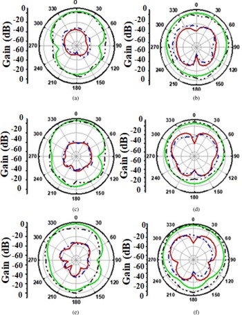
Figures 11(a)–11(f) illustrate the simulated and measured radiation pattern of the proposed high gain UWB antenna with WB-AMC. Omnidirectional radiation characteristics are observed in XY-plane (E-plane) and YZ-plane (H-plane) for all the three frequencies. Radiation pattern at 4 GHz is shown in Figs 11(a) and 11(b), at 6 GHz in Figs 11(c) and 11(d), and at 8.5 GHz Figs 11(e) and 11(f), respectively. E-co and H-co simulated pattern is shown in green color and E-co and H-co measured pattern is shown in black color. E and H-cross simulated pattern is shown in red color and measured pattern is shown in blue color. It was observed that cross-polarization level is well below 15 dB for the entire UWB frequency range.
(a–f) Simulated and measured radiation pattern for proposed low profile UWB antenna.

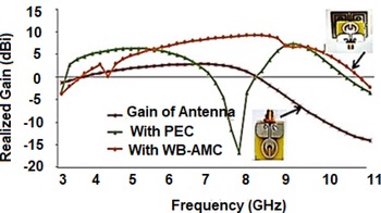
Measured and simulated radiation pattern is in good agreement for the proposed antenna. It is concluded from the radiation pattern that half power beam width coverage is wide (50° ± 5°). Simulated gain comparison among UWB antenna, UWB antenna with PEC, and UWB antenna with WB-AMC is depicted in Fig. 12. Gain enhancement was obtained for more than 6.0 GHz bandwidth from 4.0 to 10.0 GHz.
Simulated gain comparison among UWB antenna, UWB antenna with PEC, and with WB-AMC.

The gain of the proposed antenna is measured using a standard horn antenna set up and microwave source inside the anechoic chamber and shown in Fig. 13. It is also proven that a significant boost in the realized gain of the proposed antenna is achieved after the integration of WB-AMC except for Wi-Max (3.5 GHz) band.
Simulated and measured gain comparison for proposed UWB antenna.

It is observed that the gain increased from 3.2 to 9.4 dBi. Peak gain of 9.4 dBi at 8.5 GHz and an average gain enhancement of 5.8 dBi were achieved. It was further identified that at higher frequency after 9.6 GHz, the peak gain value is low after WB-AMC integration because the antenna itself has low gain from 8 to 10.6 GHz. PEC ground plane provides 180° reflection phase at resonance frequency because this signal gets destructive interference and a sudden drop of gain occurred. Moreover, antenna has better efficiency for the entire UWB band. The gain measurement formula is expressed in equation (9) from [Reference Dwivedi, Khan and Kommuri28]. G t and G r are the transmitting and receiving antenna gain, respectively. P t and P r are the transmitting and receiving end power.

Proposed antenna efficiency
The proposed antenna efficiency comparison among UWB antenna, antenna with PEC, and antenna with WB-AMC is studied and shown in Fig. 14. It was seen that efficiency was well above 80% for the entire UWB range for the proposed high gain UWB antenna. The total antenna efficiency is calculated using simulated radiation efficiency and reflection losses, respectively. It is shown that efficiency for the UWB antenna is greater than 96% for the entire UWB range and after integration of PEC efficiency decreases to 80% in mid band range near 7.5 GHz due to imperfect reflection (180° out of phase) and losses associated with metallic sheets.
Efficiency comparison among UWB antenna, PEC, and with WB-AMC.

Group delay and transmission coefficient analysis
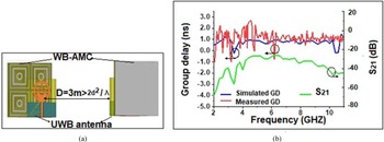
The time domain performance of UWB antenna is similarly noteworthy as in the frequency domain. The antenna should have negligible dispersion characteristics in transmitting and receiving both the modes. The group delay simulation set up in HFSS is shown in Fig. 15(a). To validate the non-dispersive nature, the simulated and measured result of group delay (~2 ns) is compared and shown in Fig. 15(b). It was observed that group delay was almost constant for the entire UWB range. Apart from this, (S 21) transmission coefficient is also simulated and seen that it is well below −26 dB for the entire UWB range. Furthermore, the novelty of the proposed UWB antenna is that it covers the entire UWB application with high gain without modifying the physical geometry of the proposed device. However, the insertion of stub helped into miniaturization of the antenna and WB-AMC integration provides high gain with less complexity.
(a) Group delay set up. (b) Simulated and measured group delay comparison for proposed UWB antenna.

Moreover, the qualitative comparison of the reference antennas with the proposed antenna is presented in Table 4 in terms of overall antenna size, bandwidth, group delay, technique used, and gain of the antenna.
Qualitative comparison of proposed work with previous reported work

BW, bandwidth; PG, peak gain; GD, group delay.
aDistance between antenna and ground plane.
Conclusion
A novel method of constant gain enhancement using WB-AMC integration is studied and proposed. Open-ended stubs (crescent-shaped for mid band and T-shaped stub for upper band of UWB) are loaded to make the antenna wideband. Curved ground approach is used to achieve UWB without affecting antenna performance. Finally, WB-AMC is integrated with the antenna to enhance the gain up to 9.4 dBi at 7.0 GHz with a 50% profile reduction. The design of WB-AMC with equivalent circuit is presented. The important attributes of the acclaimed antenna are low profile, UWB range, omni-directional radiation pattern, and high gain. Better correlation between simulation and measured results established that the proposed antenna is a potential option for wireless and UWB application with low cost.
 Dr. Ravi Prakash Dwivedi obtained B.E. degree from RGPV, Bhopal, Madhya Pradesh, India and M.Tech. degree from the Indian Institute of Technology (Kharagpur), Kharagpur, India. He obtained Ph.D. degree from the School of Electronics Engineering VIT Chennai campus, Chennai, Tamil Nadu, India. Currently, he is an Assistant Professor senior and microwave and antenna measurement lab in-charge in the School of Electronics Engineering, VIT Chennai, Tamil Nadu, India. He has published 25 research papers in various international journals and conferences. His current research interests involve design and analysis of high gain antenna, wideband antenna and their application toward UWB, and active integrated antenna.
 Dr. Usha Kiran Kommuri completed her Ph.D. on microwave antennas from Gulbarga University, Karnataka in 2007. She has worked as a Project Associate from 2007 to 2009 in Microwave Lab, ECE, Indian Institute of Science (IISc), Bangalore, India and Project Scientist on RF MEMS from 2010 to 2012 at the Indian Institute of Technology (IIT), Delhi, India. Presently she is working as an Associate professor in the School of Electronics Engineering, VIT Chennai campus, Tamil Nadu, India. She has published more than 50 research papers in various national and international journals and conferences on microwave antennas and RFMEMS.
 Dr. Sudipta Das was born in West Bengal, India. He has obtained his B.Tech. and M.Tech. degrees from West Bengal University of Technology (presently MAKAUT). He has earned his Ph.D. degree from the University of Kalyani, India. He is currently working as an Associate Professor in the Department of Electronics and Communication Engineering at IMPS College of Engg. & Technology, West Bengal, India. He has 12 years of teaching and 7 years of research experiences. His research interests are microstrip antennas for microwave, mm-wave and THz communication systems, flexible antenna design, filter design, FSS, RFID, microwave components, and THz systems.
 Dr. Soufian Lakrit was born in Kariat Ba Mohamed, Taounate, Morocco in 1985. He obtained the License degree in physics from the Faculty of Sciences of Fez in 2009 and the Master degree in microwave and telecommunication from the National School of Applied Sciences (ENSA), Sidi Mohammed Ben Abdallah University of Fez in 2011. He obtained the Ph.D. degree in electrical engineering from Mohammadia School of Engineering, Mohammed V University of Rabat. He is working as an Assistant Professor in the Applied Mathematics and Information Systems Laboratory, EST of Nador, Mohammed First University, Oujda, Morocco. His research interests include RF/microwave, antennas theory, UWB antennas, MIMO antenna, reconfigurable and miniaturization, and microwave/mm-wave integrated circuits and devices.
 Dr. Vishal Goyal completed his Bachelor of Engineering (B.E.) in electronics from Nagpur University in 2001, Master of Technology in digital communication from UP Technical University, Lucknow, India, 2006 and Ph.D. from GLA University, Mathura, India, 2016. Currently he is working as a Professor and Director IQAC Institute of Engineering & Technology, GLA University. He has published more than 40 reputed and peer-reviewed articles in various international journals and conferences. His research interests include nonlinear systems, adaptive nonlinear control, process control, and RF microwave.